
Abstract
The HIT load-carrying exoskeleton is designed for enhancing the operator’s load-carrying capability. Human walking has the characteristics of diversity and randomness. It requires that the sensing system of exoskeleton could detect and identify the random motion of human body. In this article, a human–machine force interaction designing architecture is proposed for HIT load-carrying exoskeleton. The human–machine interactive forces at the kinematic terminals (the back and feet) are detected for the human movement identification. Four basic body modalities during the movement process are proposed, which could be automatically identified by the sensing system. The kinematic models for the swing leg and supporting leg are established, respectively. A positional deviation feedback control method based on the interaction force detection is designed. The experiments show that the human–machine interaction force detection at the back and feet and the identification of different body modalities and movement intention are feasible. The interactive forces on the back are far less than the payload, indicating that the exoskeleton has good power-assisted effect.
Keywords
Introduction
The lower limb powered exoskeleton is a human–machine system with functions of following the human movement and providing assistance. Generally, the anthropomorphic designing structure is adopted to realize the motion space coupling between the operator and the exoskeleton. Besides, the leading role of human in the controlling loop and the optimal man–machine interaction force control should be fully considered to realize the man–machine coordination and help the load-bearing walking.
Human walking is a certain cyclical movement such as straight forward on flat ground. Furthermore, it can also perform as arbitrary and random movement in complex environments such as grassland, mountainous region, slopes, and steps. The changes in velocity, step length, or walking direction would increase the irregularity of the movement as well. All these factors draw higher demand in the human–machine interaction system design and the exoskeleton control. Although there have been several research institutions that have presented some significant prototypes, it still shows certain distance away from practical applications. The accurate man–machine interactive detection, body movement intention identification, and reasonable exoskeleton control strategy are key factors for the improvement of movement flexibility and power-assisting effect.
In the previous studies, there are several different human–machine interaction schemes and control strategies that have been developed for the exoskeleton robots. The representative methods include the sensitivity amplification control, electromyography (EMG) signal control, man–machine interaction force control, zero moment point (ZMP) balance control, gait cycle dividing control base on foot pressure distribution, or a combination of the aforementioned control methods.
The Berkeley lower extremity exoskeleton (BLEEX)1,2 is a hydraulically powered exoskeleton that can walk at the speed of 1.3 m/s with a payload of 34 kg. The human plays a role in the control loop to enable the human–machine system moving in concert with each other. A sensitivity amplification control algorithm is proposed to drive down as much as possible of the wearer’s forces and torques in the walking process. So it need not to measure the man–machine interaction force, human position, or EMG signal of the wearer. However, it needs accurate dynamic model and robustness to parameter uncertainty.
Hybrid assistive limb (HAL) series exoskeletons developed at the University of Tsukuba are mainly aimed at civilian applications such as assisting handicapped and elderly people.3,4 Also in the latest generation, a whole-body version named HAL-5 (Type-B) 5 has been proposed to assist physical capabilities such as materials handling. According to different applications, different man–machine interaction methods are used including the operator’s joint angles, EMG signals, and the ground contacting force to estimate the wearer’s movement intention. 6
Massachusetts Institute of Technology (MIT) has developed a quasi-passive lower limb exoskeleton relying on the energy storage of suitable activated springs and magnetorheological dampers.7,8 It aims at reducing the power requirements of the exoskeleton and the metabolic cost of the wearer. Also another actuation strategy by setting a linear series elastic actuator at the hip joint has been designed to augment the hip flexion/extension movement. 9 Sensing system detects the hip and knee angles; the vertical force and the bending moment of the shank; the human–machine interaction force at thigh; and the driving torque at the hip. Then, the state-machine controller for the hip and knee is designed and operated separately based on the sensing system.
The Institute of Intelligent Machines of China Academy of Science has designed a wearable robot to give assistance for the wearer’s locomotion. 10 It adopts four two-dimensional force sensors mounted on inner side of the thigh and shank to gain information of human movement intentions.
The six-dimensional force sensor is also a common detection way for the human–machine interaction force detection. There are several exoskeleton prototypes that adopt six-dimensional force sensors to measure the human–machine interaction forces at the back and feet. The interaction forces are used for the identification of human movement intentions and the exoskeleton control. The representative work in this method includes the “The Body Extender” by the PERCRO lab of Scuola Superiore S. Anna of Pisa in Italy,11,12 the DSME wearable robot in Korea designed for workers’ heavy physical labor, 13 the “Powerloader” by the Active Link Co. Ltd. of Japan,14,15 and so on.
By contrast, the EMG signals detection requires pasting electrode slices on the specific location of human skin, which is not convenient for the exoskeleton wear and daily use. The foot pressure distribution test cannot adapt to uneven road surface. The interaction force detection of thigh and shank requires that the exoskeleton leg is in parallel with the wearer’s leg, which is difficult to realize due to the changes in the joint rotation instantaneous centers. Besides, the constriction or relaxation of leg muscles will also cause additional interference to the detection. The accurate dynamic modeling and control cannot be flexible to adapt to the changes in the payload and external environment interference.
In this article, a human–machine force interaction designing architecture is proposed for the HIT load-carrying exoskeleton (HIT-LEX). The human–machine interactive forces at the kinematic terminals (the back and feet) are detected for the human movement identification and exoskeleton control. Then, the power-assisted effect is studied experimentally.
HIT-LEX and its sensing system
HIT-LEX is designed for the enhancement of the human load-carrying capability in various road environments. The wearing convenience and movement flexibility could be acquired by the reasonable structural design. Besides, the human movement identification and good power-assisted capability rely on the comprehensive usage of multiple sensors and corresponding control strategy based on the sensing system.
Introduction of the HIT-LEX and the degrees-of-freedom distribution
The human–machine system of HIT-LEX is shown in Figure 1(a). Anthropomorphic designing architecture is employed for the confirmation of the degrees-of-freedom (DOF) distribution and structure sizes. The active driving units are installed on the toilsome joints, including the flexion/extension rotations of the hip and knee joints. The HIT-LEX and human body are tied together by bundling belts with rapid buckles or nylon Velcro at the back and feet, which are convenient to put on or take off. Meanwhile, a 2-DOFs flexible auxiliary bundling device is installed on the exoskeleton thigh, which will also help the man–machine coupling and cause no interference for the force detection at the feet and back.
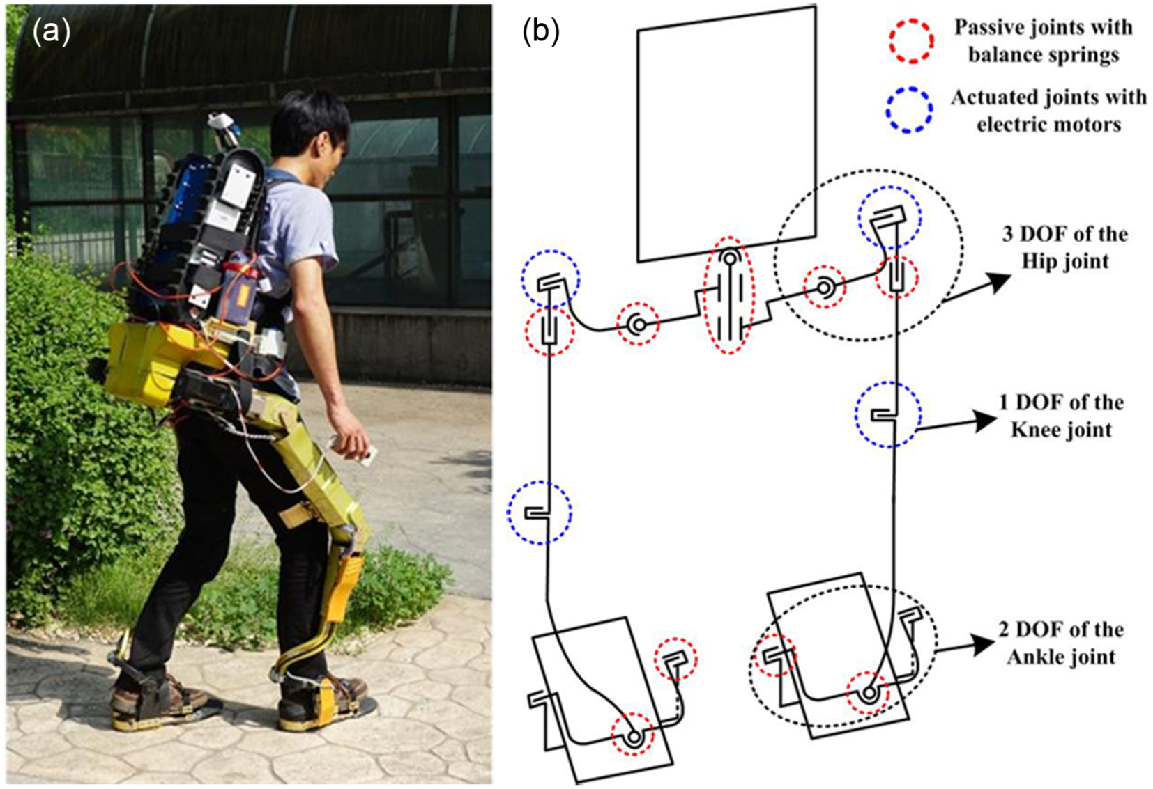
HIT load-carrying exoskeleton and the DOFs distribution: (a) the man–machine system and (b) the DOFs distribution of HIT-LEX.
Figure 1(b) is the DOFs distribution diagram of HIT-LEX, which has a total of 14 DOFs (2-DOFs at the waist, 3-DOFs at the hip joint, 1-DOF at the knee joint, and 2-DOFs at the ankle joint). Besides, there is a redundant internal/external rotation DOF at the waist for each hip joint, which ensures the hip joint do small internal/external rotation movement when the hip joint degenerates into a 2-DOFs joint in some special postures. However, this redundant DOF is designed with balance springs with large stiffness to maintain its balance position. Therefore, it is mainly the internal/external DOF of the hip joint rotating in the normal walking.
A combination of active driving and passive energy storage is adopted for the power-assisted walking. In detail, the flexion/extension rotations of the hip and knee are actuated by the electric motors; the hip abduction/adduction DOF and the ankle flexion/extension DOF are installed with unidirectional energy storage springs to achieve the power-assisted effect. All the other passive DOFs are settled with counterbalancing springs.
Electronic hardware and the sensing system
As the wearable power-assisted equipment, HIT-LEX must be able to real-timely detect, judge, and follow the movement of human legs. Figure 2 shows the arrangement of the sensing system.

Arrangement of the sensing system.
The multiple DOFs of the exoskeleton and the various body postures in the walking show that multi-sensors are needed for the human–machine interaction. By the kinematic terminal interactive force detection, the human movement intentions could be acquired. However, some other information is also needed for the exoskeleton control, including the posture of human body and the contact conditions to the environment. As shown in Figure 2, there are multi-dimensional force detection at the back and feet, the exoskeleton attitude measurement, the angles detection at the appropriate joints, and the foot-landing detection under foot.
First, the exoskeleton posture and ground contacting conditions should be obtained by the attitude measurement, joint angles detection, and the foot-landing detection, which are the foundations of the exoskeleton control. Then, the human–machine interaction forces are detected by the kinematic terminal interactive force devices. The small interaction forces represent that the exoskeleton follows the body movement flexibly and the power-assisted effect is favorable.
Figure 3 shows the electronic hardware platform of HIT-LEX, including the upper computer module, the 48 V power module, two controller area network (CAN) bus networks for the legs, data acquisition nodes at the back and feet, and four motor actuators at the hip and knee joints.

Electronic hardware structure of the human–machine interactive perception system.
Human–machine force interaction devices design
There should be enough space at the back of the exoskeleton for the payload. The plantar room is also rigorous for the installation of the man–machine interaction device. Therefore, the human–machine interactive force detection devices should have a flat structure. Besides, the detection ranges, sensitivity, and security protection limit should be considered in the design.
Mechatronic integration of the exoskeleton sensing shoe
There are several kinds of information to be detected at the exoskeleton foot, including the human–machine interaction forces, the rotation angles of the 2-DOFs at ankle joint, and the foot-landing detection. For the foot-landing detection, it relies on three thin-film pressure sensors, one fixed at the heel and the others at the forefoot as shown in Figure 4. They are used as a state switch to detect the instant that the relevant leg switches into the supporting phase.
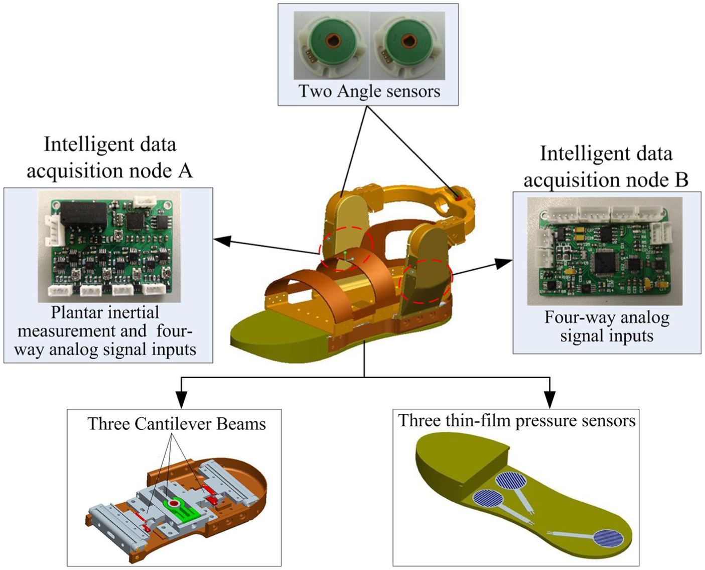
Structural composition of the multi-sensing shoe.
For the foot-lifting detection, it is unserviceable to be detected by the thin-film pressure sensors as the exoskeleton needs to first detect the human movement intention and follow it. Then, the measured values of the pressure sensors could return to zero. So the vertical component force of the plantar interaction forces is used for the foot-lifting detection.
The exoskeleton sensing shoe integrates the multi-sensing detection system and circuit components into the mechanical structure, leading to a compact and anthropomorphic appearance. Two CAN bus intelligent data acquisition nodes (A and B) are installed on both sides of the foot, each of which has four-way analog data collection channels to collect the three cantilever beams, three pressure sensors, and two angle sensors on ankle joint. Besides, there is attitude measurement at the intelligent data acquisition node A.
The plantar interaction forces are detected by the six-link mechanism and three cantilever beams as shown in Figure 5. There are mechanical limit protections on the cantilever beams and the measurement range is ±10 kg, which will guarantee that the wearer’s weight will not cause damage to the cantilever beam in the supporting phase and the high sensitivity could still be acquired in the swing phase. In Figure 5, the green line represents the foot binding plate connecting to the human foot, and the black lines are fixed to the bottom plate of the exoskeleton foot.
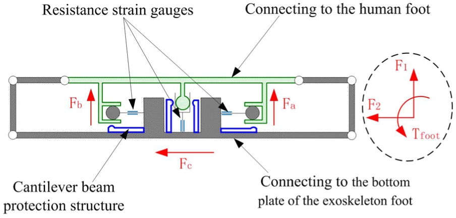
Plantar man–machine interaction device and the mechanical limit protections.
The detected forces by three cantilever beams are marked as

where
Dorsal man–machine interaction device
The dorsal human–machine interactive force detection is also aimed at two-dimensional forces and one-dimensional torque on the sagittal plane. The dorsal binding part is connected to the waist platform through the man–machine interaction device as shown in Figure 6. The dorsal detection information includes the attitude measurement of the back and three forces of the cantilever beams. Therefore, one CAN bus intelligent data acquisition node is sufficient for the data acquisition which contains four-way analog data collection channels.
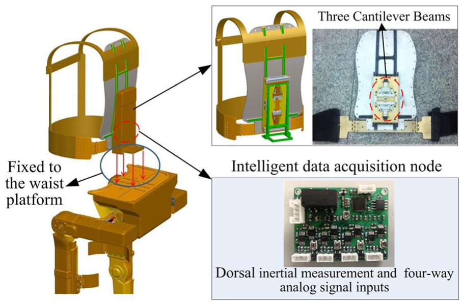
Dorsal man–machine interaction device and the intelligent data acquisition node.
The schematic diagram of the dorsal man–machine interaction device is shown in Figure 7, which is similar to the foot. The detected forces by three cantilever beams are marked as
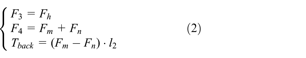
where

Dorsal man–machine interaction device and the mechanical limit protections.
Cantilever beams calibration
The structure of the man–machine force interaction devices at the back and feet is almost the same, using an elastomer which has three cantilever beams. Each cantilever beam can measure the bidirectional force. In order to improve the accuracy of the sensor signal, the beams are calibrated as shown in Figure 8. The elastomer is fixed and a tray is hung to the cantilever beam’s stress point. The weight of the tray is known and constant. Then, a standard weight of 100 g is increased progressively on the tray. Finally, the data were collected and fitted using the MATLAB linear fitting toolbox. It can be seen in Figure 8 that the strain values of both tension and compression are consistent and with good linearity.

Cantilever beams calibration for the man–machine force interaction devices.
Basic body modalities and automatic identification
The frequent conversion between supporting phase and swing phase for each leg will lead to the changes of the system kinematics configurations. So it is necessary to establish the corresponding kinematic models of different configurations for the exoskeleton control. Accurate judgment of the system kinematics configurations and the real-time detection of the transition moment will contribute to the exoskeleton control.
Description of the basic body motion modalities
The various movement conditions of human lower limbs are ground walking, running, uphill, climbing stairs, squatting down, and standing up. There are several basic body motion modalities, including the single support leg, single swing leg, double support legs, and double swing legs as shown in Figure 9. The exoskeleton needs to judge each kind of morphology accurately and then carry out the corresponding control strategy.
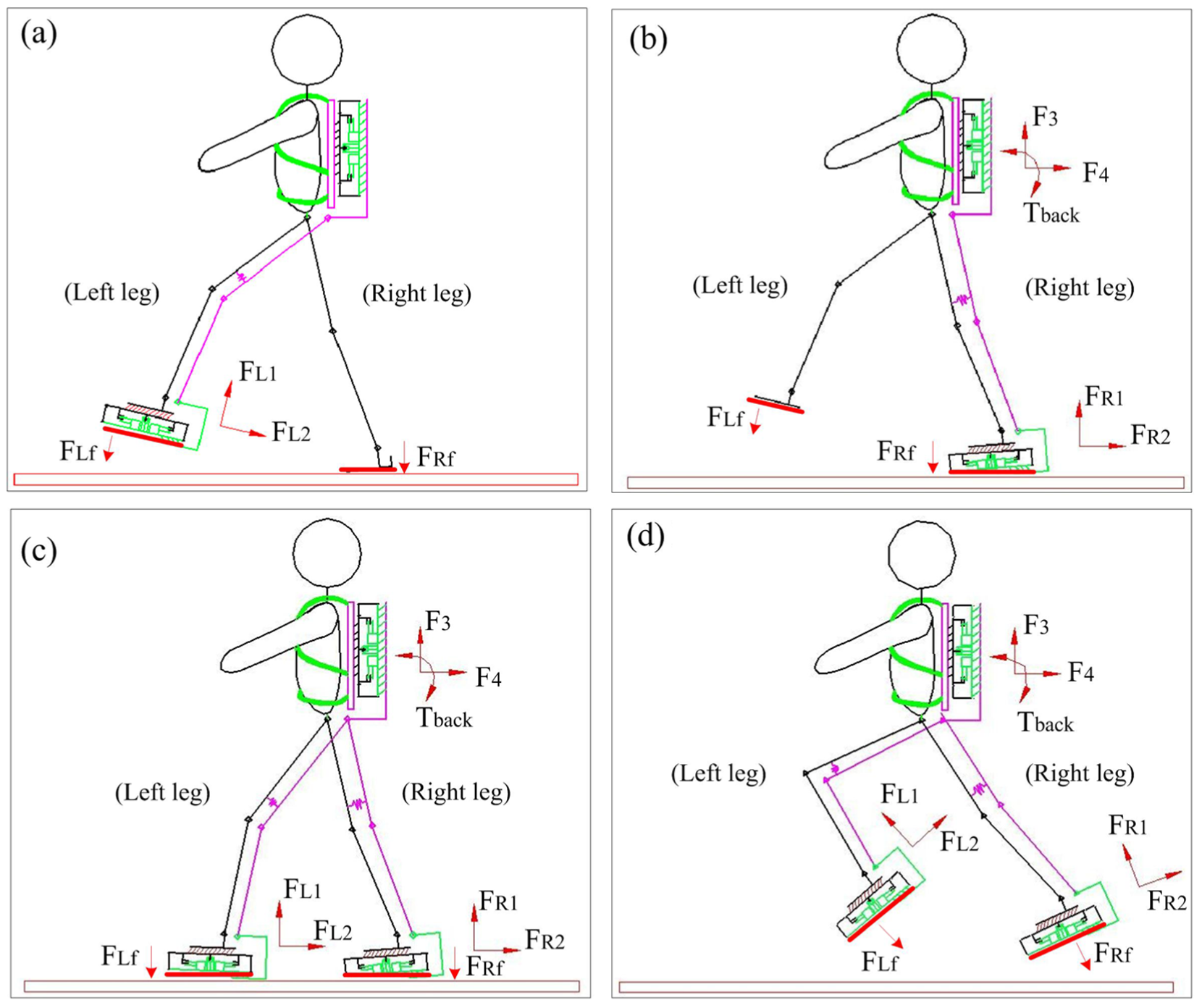
Four basic body motion modalities and the sensing information acquisition: (a) single swing leg detection, (b) single support leg detection, (c) double support legs detection, and (d) double swing legs detection.
Figure 9 shows the human movement intention detection methods based on the four basic body motion modalities. After the judgment of the foot-landing or foot-lifting states for each leg, the exoskeleton robot follows the human legs’ motion to provide appropriate power assistance based on the man–machine interaction force detection at the feet and back.
For the control of each leg, there are only two phases: the supporting phase and swing phase. In the supporting phase, the sum detected value (
Gait switching strategy between different modalities
The identification of the transition between four basic body motion modalities requires the integration of a variety of the detected information. For each exoskeleton foot, it includes the transition from swing state to supporting state, and the transition from supporting state to swing state.
For the detection of the foot-landing moment, it is triggered by the increase in the sum value (
Figure 10 shows the transform relationship between the double legs supporting phase, the double legs swing phase, and the single-leg supporting phase (single left or right leg). The triggers between the four states are shown in Table 1.

State-machine diagram for the HIT-LEX gait switching controller.
Triggers between different modalities of HIT-LEX.

HIT-LEX: HIT load-carrying exoskeleton.
Control schemes and implementation on HIT-LEX
Control strategy based on the interactive force detection
HIT-LEX is a wearable device, which is highly coupled with human body and its payload changes in a large range. The dynamic model is hard to be established accurately. A positional deviation feedback control method based on the interaction force detection is designed for the exoskeleton control as shown in Figure 11. The expected terminal velocity is obtained by the current speed and the expected speed increment. The control scheme focuses mainly on the terminal velocity estimation and the calculation of the expected velocity for each driving joint.

Control block diagram of HIT-LEX.
For the single swing leg, the exoskeleton torso is regarded as the fixed base and the exoskeleton foot acts as the kinematic terminal. It could be seen as a plane two-linkage mechanism. For the single supporting leg, the foot is regarded as the fixed end and the trunk is regarded as the free end. In this state, the system can be simplified to a plane three-linkage mechanism. As shown in Figure 11,
In the double-leg swing state such as the jumping-up condition, each leg is regarded as a single swing leg and the expected kinematic terminal speed is calculated, respectively. In the double-leg supporting state, the expected kinematic terminal speed of the exoskeleton torso is unique, which is mapped into the joint space of each leg, respectively, to get the expected speed of each driven joint.
Swinging leg control
The swing leg could be seen as a plane two-linkage mechanism as shown in Figure 12. The D-H coordinate system is established for the kinematics analysis.

which is determined by the initial velocity
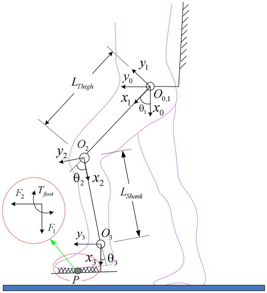
D-H coordinate system of the swinging leg on sagittal plane.
The transformation matrix of the kinematic terminal is recorded as

where

Support leg control
The supporting leg could be seen as a plane three-linkage mechanism and the D-H coordinate system is established for the kinematics analysis as shown in Figure 13. Both the trunk attitude and the position need to be controlled. There are three DOFs on the sagittal plane but only two active driving units are settled. As an under-actuated system, the expected speeds of joints cannot be calculated directly.

D-H coordinate system of the single support leg on the sagittal plane.
An equivalent inverted pendulum model with alterable pendulum length is proposed in Figure 14. Arbitrary movement can be realized by controlling the pendulum length

Equivalent inverted pendulum model.
The expected angular velocity of the hip joint can be calculated as follows

The expected speeds of point H on the hip joint are as follows

The velocity component of the point H in the direction of

The relationship between the pendulum length

Then, the expected angular velocity of the knee joint can be calculated as follows

where
Experimental performance
The effect of the control method based on the kinematic terminal interactive force detection needs to be experimentally verified. Experiments for the swing leg and supporting leg are conducted, respectively. Then, the continuous walking experiment is done to detect the load-bearing performance and the stability of transition between different states based on four basic body motion modalities.
Swinging leg experiment
The swing leg experiment aims at testing the sensitivity and flexibility of the exoskeleton leg to follow the human foot’s movement. As shown in Figure 15(a), the human foot swings freely in the experiment. Figure 15(b) shows the terminal trajectory under Cartesian coordinate system according to the detected data of the hip and knee joint angles. It can be seen in the diagram that the exoskeleton can follow the movement of the human foot smoothly.

Swing leg experimental process: (a) periodic swinging of human leg and (b) foot trajectory of HIT-LEX.
The two-dimensional forces measured by the plantar man–machine interaction device are shown in Figure 16. The two-dimensional forces are maintained in a small range of about ±20 N. The human foot feels portable and flexible in the swing process.
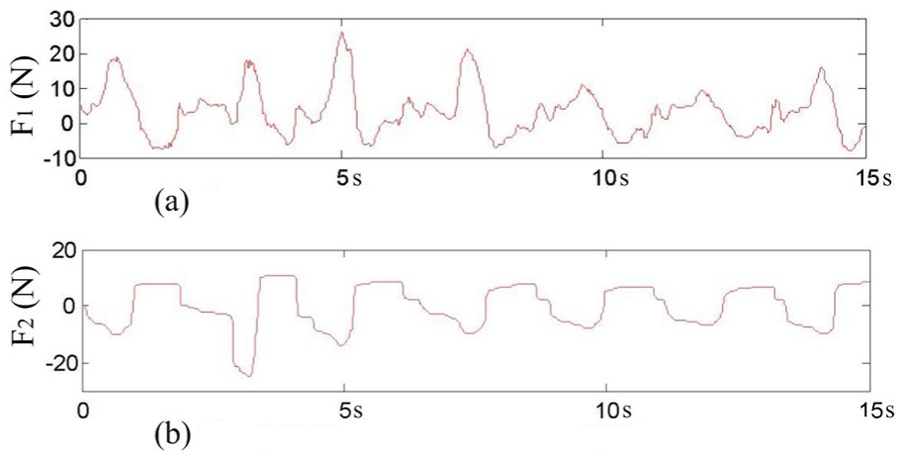
Two-dimensional forces between human and exoskeleton feet: (a) component force in the up-down direction and (b) component force in the anteroposterior direction.
Support leg experiment
The control methods of the single-leg supporting state and the double-leg supporting state are approximately same. The supporting leg experiment aims at testing the load-bearing performance and the reasonability of the equivalent inverted pendulum model. The squatting down and standing up experiment is done with a payload of about 30 kg as shown in Figure 17(a). The two feet are together in the experiment and the movements of two legs are consistent. All the two-dimensional forces, one-dimensional torque, and the angles of the hip, knee, and ankle joints are recorded. Figure 17(b) is the calculated trajectory of the point B in Cartesian coordinate system. It could be seen that the exoskeleton follows the movement of human upper body smoothly.

Support leg experimental process: (a) process of squatting down and standing up and (b) dorsal trajectory of HIT-LEX.
Figure 18 is the changing curves of the dorsal man–machine interactive forces, which are slightly larger than the plantar man–machine interaction forces in the swing phase. However, they are far less than the actual load on the back, which shows that the exoskeleton takes a good power-assisted effect.

Two-dimensional forces and torque between human back and HIT-LEX: (a) component force in the anteroposterior direction, (b) component force in the up-down direction, and (c) dorsal man–machine interaction torque.
Continuous load-bearing experiment
The swinging leg and supporting leg experiments have preliminarily verified the feasibility of the control strategy. However, the continuous walking is more complex as it needs to detect the stability of transition between different body motion modalities. The continuously load-bearing walk is done outdoors as shown in Figure 19. An emergency stop handle is added in the experiment for safety consideration. A crawler robot is used as a payload, which is approximately 30 kg.

Continuous load-bearing walking in the outdoor environment.
The change curves of the expected angular velocity and the actual angular velocity of the right hip and knee joints are shown in Figure 20. From the diagram, it could be seen that the actual angular speeds are nearly consistent with the desired angular speeds. The trajectory curves change periodically and smoothly.
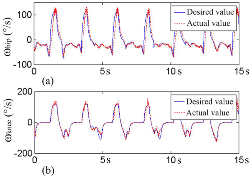
Desired angular velocities and actual angular velocities of right hip and knee joints: (a) the right hip joint and (b) the right knee joint.
Figure 21 shows the interaction forces and torque at the back in continuous walking. The blue dashed line shows the gait phase determined by the ground contact force of the left foot. High level is the supporting phase and low level is the swing phase. The two-dimensional forces in continuous walking are maintained in a small range of about ±20 N, which is smaller than the forces in the squatting down and standing up experiment. This is because that the human back is with small fluctuation in the vertical direction and with almost constant speed in the horizontal direction. The torque on the sagittal plane is in a range of ±6 Nm, which is also smaller than the torque in Figure 18. The experiment shows that the human–machine interaction forces and torque on the back will be relatively reduced if the human motion is smooth and gentle.

Two-dimensional forces and torque on the human back during continuous load-bearing walking: (a) horizontal component force on the back, (b) vertical component force on the back, and (c) interactive torque on the back.
In conclusion, the experiment shows that the identification of different body modalities is workable and the transition between different modalities is stable. The actual load on the human back is far less than the payload (30 kg), which shows that the most of the burden is supported by the exoskeleton and the walking process is effortless. The HIT-LEX exoskeleton could achieve good power-assisted capability in load walking based on the man–machine interactive force detection at the back and feet.
Conclusion
A human–machine force interaction designing method has been proposed for the human movement identification and control of the HIT-LEX. The human–machine interactive forces at the kinematic terminals (the back and feet) are detected based on the specially designed dorsal man–machine interaction device and sensing shoes. The auxiliary information including the exoskeleton attitude, the joint angles, and the foot-landing conditions is also detected to confirm the exoskeleton posture and the contact conditions to the environment. Four basic body motion modalities could be automatically and effectively identified relying on the designed sensor detection system. For each kind of human body motion modalities, the kinematic model is established to analyze the exoskeleton control. The expected speeds of the hip and knee joints are calculated, respectively, for the speed control in the joint space. The continuous load-bearing walk experiment shows that the identification and transition of different body motion modalities are feasible. The actual load on the human back is far less than the payload, which shows that the exoskeleton has good power-assisted effect.
Footnotes
Academic Editor: Nicolas Garcia-Aracil
Declaration of conflicting interests
The author(s) declared no potential conflicts of interest with respect to the research, authorship, and/or publication of this article.
Funding
The author(s) disclosed receipt of the following financial support for the research, authorship, and/or publication of this article: The work reported in this article is funded by “National High Technology Research and Development Program of China (863 Program)” (Grant No. 2012AA041505) and “Self-Planned Task of State Key Laboratory of Robotics and System (HIT)” (Grant No. SKLRS201201A02).