
Abstract
A numerical method is proposed to determine the heat transfer capability of the high-temperature heat pipe and the stagnation temperature with supersonic vehicle leading edge applications. The finite element method is employed here to perform the temperature field simulation. Without considering the heat transfer limitations of the heat pipe, such as capillary limit and sonic limit, both numerical and experimental results indicate that equivalent high thermal conductivity method is a reasonable way to simulate the heat transfer capability of the high-temperature heat pipe in preliminary design of a heat-pipe-cooled leading edge. Several important parameters’ effects on the thermal protection performance are also numerically investigated.
Introduction
As a hypersonic vehicle travels through the earth’s atmosphere, the high local heating causes very high aerodynamic heating fluxes and high temperatures. Stagnation regions such as nose caps, wing and tail leading edges are critical design areas of hypersonic vehicles. Several methods of cooling and protection are possible for various surface geometries.1,2 Although the thermal protection structure (TPS) concepts have been used on the Space Shuttle for over 30 years, they have been proved to be quite ineffective, as the inspection and reparation of the TPS tiles after each flight are very time/cost-consuming. At the same time, next generation reusable launch vehicle (RLV) must be capable of sustaining consistent repeated aerodynamic heating without damage or deterioration. So the “hot structure” concepts might be a very good alternative. 3 The hot structure itself is conceived to resist the aerodynamic heating without employing TPS tiles. One suggested hot structure concept of leading edges is to place heat pipes inside the structure 4 as shown in Figure 1.

A cross-sectional schematic showing the operating principles and relevant geometry of a heat-pipe-cooled leading edge.
For aerodynamic reasons, hypersonic vehicles require sharp leading edges, with millimeter scale radius. When the edges are that sharp, the heat flux into the structure is very intense, and the heat flux at the stagnation point could as high as 5 MW/m2. So aerodynamic heat must be redistributed quickly from the stagnation area to the downwind surfaces of the vehicle where heat flux is weak. The heat pipes are formed to match the shape of the leading edge and are installed in a roughly chordwise orientation. High heating near the stagnation line vaporizes the working fluid in the heat pipe. The vapor then flows axially through the pipe to the cooler portion, which experience lower heating. Because this section is cooler, the vapor condenses and rejects the heat absorbed near the stagnation area. The condensed liquid is returned in an internal wick to the evaporating area by capillary effect. This process reduces the stagnation temperature, accompanied by a temperature increase in the aft portion of the leading edge, and averages the temperature along the axis of the heat pipe. For one thing, heat pipe decreases the temperature gradient in leading edge, and for another thing, it also decreases the thermal stress caused by temperature gradient.
The heat-pipe-cooled leading edge had been widely studied in terms of theory, computation, and experiment with steady or transient considerations until recently. Cao and Faghri 5 proposed a complete mathematical model for transient two-dimensional high-temperature heat pipes and investigated the transient responses of heat pipes to a pulsed heat input. Glass 6 proposed series of closed-form equations to evaluate heat-pipe-cooled leading edge design feasibility. Camarda and Masek 7 investigated the performance of lithium-filled heat pipe, and they designed, fabricated, and tested several refractory metal and niobium alloy heat pipes. Jacobson and Lou 8 studied the high-temperature corrosion failure of a sodium Inconel 600 heat pipe using metallographic, electronic microprobe, oxygen source ion probe, and X-ray analysis. Rovang and Juhasz 9 discussed development and proof-of-concept testing of a lightweight C/C space radiator heat pipe. Glass and colleagues10–12 fabricated and tested Mo-Re heat pipes embedded in C/C structure with a D-shaped cross section, and they found that the heat pipe did operate isothermally over a significant portion of its length. Steeves et al. 4 investigated the feasibility of metallic structural heap pipes as sharp leading edges for hypersonic vehicles, but they did not consider the temperature-dependent material properties which could be obviously changed at high temperatures.
The design of a heat-pipe-cooled leading edge is very complex because of the numerous variables involved. One of the key problems is the numerical simulation of the heat transfer capability of the heat pipe. For simplicity, heat transfer capability of the heat pipe in this article is related to the stagnation temperature of the heat-pipe-cooled leading edge where heat pipe is embedded, that is to say, for a given aerodynamic heat flux, the smaller the stagnation temperature is, the larger the heat transfer capability of heat pipe will be. The comprehensive study of the heat transfer capability of the heat pipe includes the whole operational cycle for heat-pipe-cooled leading edge, from heat pipe starts up, working fluid vaporizes, working vapor flows and condenses, and working fluid refluxes. This procedure is very time-consuming and not fit for the preliminary design and evaluation requirement of the heat-pipe-cooled leading edge.
The purpose of this article is to present a simple and fast numerical method that can be used in preliminary design of a heat-pipe-cooled leading edge. Although some restrictions are adopted in this method, it appears to be a useful tool for the preliminary thermal design of the heat-pipe-cooled leading edge.
Mathematical model
Actually, there are several limitations to the heat transfer capability of a heat pipe, such as capillary limit, sonic limit, boiling limit, entrainment limit, viscous limit, frozen start-up limit, and vapor continuum limit. In preliminary design stage, these limitations are omitted and the heat pipe is assumed to have unlimited heat transfer capability. The only thing of concern is the stagnation temperature reduction result of the heat-pipe-cooled leading edge, so only heat conduction in the structure and radiation heat transfer outside the structure are taken into account here.
Governing equations
We consider the following heat conduction problem on the domain

It is noted that the so-called equivalent high thermal conductivity method (EHTCM) is adopted here to simulate the super high heat transfer capability of the heat pipe, and it considers the vapor channel of the heat pipe as a solid component with very high thermal conductivity, which implies that the domain


In equations (1)–(3), ∇ denotes the gradient operator;
At the outer wall surface of the structure, both distributed aerodynamic heat flux and radiation heat flux are applied

where
There are two basic approaches to simulate the super high heat transfer capability of the heat pipe. The one is to specify temperature on the inner surface of the heat pipe which is known as the Dirichlet boundary condition, and the specified temperature is usually equal to the working temperature of the heat pipe working fluid. This prescribe temperature method (PTM) is based on the fact that the heat pipe is a good isothermal body, and even a very small temperature difference exists in the heat pipe, the heat pipe gets into work immediately to balance it. 13
The other approach is the so-called EHTCM and the advantage of the EHTCM is that instead of considering the complex vapor–liquid phase transition phenomenon inside the heat pipe, the heat transfer capability of the heat pipe can be obtained easily through the stagnation temperature based on heat conduction analysis, and this simplification can save a lot of computation time, which is very important in the preliminary design of a heat-pipe-cooled leading edge. El-Nasr and El-Haggar 14 investigated the effect of the working fluids, container materials, and the wick structures on the effective thermal conductivity of heat pipe, and found that the effective thermal conductivity of heat pipe can reach as high as 1E5 W/m K.
Practically, the wall region of the heat pipe is included in the model, while the wick region is not. At the same time, the thermal conductivity of the material and the radiation heat flux are temperature dependent, making the problem a complicated nonlinear one.
Numerical method
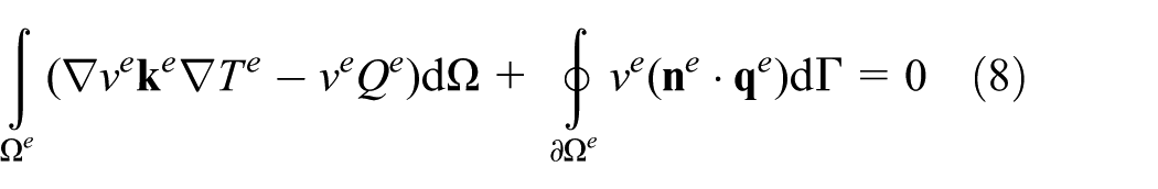
In order to obtain the approximate solution of the problem, the above governing equations are discretized by the finite element method. By taking the inner product of equation (1) with weighting functions v, over the solution domain

where weighting function v is a set of arbitrary functions equal in number to the number of equations involved.
Let

Integrating by parts the terms associated with the divergence in equation (6) leads to

where heat flux
Substituting equation (7) into equation (6), the following form can be obtained
Suppose that the element temperature field

where
In order to obtain a Galerkin style formulation, the weighting functions

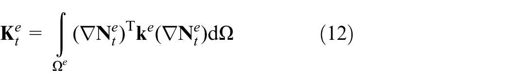
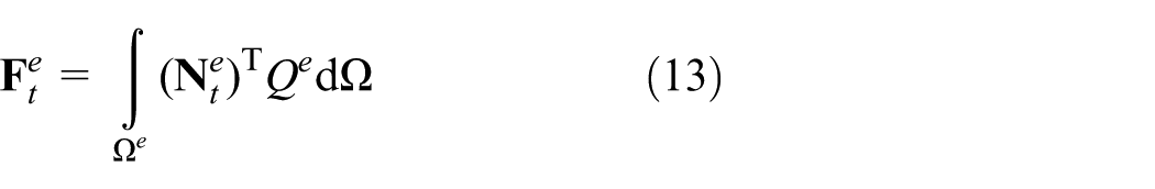
Substituting equations (9) and (10) into equation (8), the following finite element equations can be obtained

where

For this problem, one may assemble the elemental equations to form the global equations, and after imposing the Dirichlet boundary conditions, the assembled equations can be solved by traditional techniques that are widely employed for the finite element method.
Validation of the proposed method
In order to validate the present method, a conventional cylindrical heat pipe embedded in a C/C cylinder structure was investigated, and the numerical results were compared with the experimental data. 15
The geometry of the composite structure is shown in Figure 2. The material of the outer structure is three-dimensional braid C/C composite material, and the material of inner heat pipe is superalloy Inconel 600. The working fluid of the heat pipe is alkali sodium. The C/C composite material is assumed to be isotropic and temperature independent in the present numerical simulation, and the thermal conductivity and density are 66.1 W/m K and 1960 kg/m3, respectively. The density of Inconel 600 is 8430 kg/m3, and the thermal conductivity is temperature dependent which can be found in Liu et al. 16 The structure is assumed to have an initial temperature of 300 K.

Geometry of a cylindrical heat pipe embedded in a C/C cylinder.
The distribution of thermal flux applied on the outer surface of the spherical head and flat part is given in Figures 3 and 4, respectively. It can be seen from Figure 3 that the aerodynamic heat flux changes dramatically from 3000 to 218 kW/m2 in a distance of 17 mm, while decreases slowly from 218 to 192 kW/m2 in a distance of 300 mm in Figure 4. The numerical model with EHTCM is shown in Figure 5, and 24,530 nodes and 23,861 linear axisymmetric heat conduction elements are adopted here. In numerical calculations, Stefan–Boltzmann constant is 5.67 × 10⁻⁸ W/m2 K4, the surface emissivity is 0.8, and the outer space temperature is 300 K.

Heat flux applied on the outer surface of the spherical head.

Heat flux applied on the outer surface of the flat part of the structure.

Axisymmetric (2D) finite element model of the experimental model with boundary conditions for numerical simulation.
For EHTCM, the inner space of the heat pipe is meshed with solid element with high effective thermal conductivity material, and the effective high thermal conductivity of the heat pipe is set to be 1E4 W/m K. For PTM, the temperature of inner space of the heat pipe is prescribed to be a constant value of 1056 K in this article where alkali metal is chosen as the working fluid.
Numerical results of the temperature field given by EHTCM and PTM are shown in Figures 6 and 7, respectively. It can be seen from Figure 6 that the maximum temperature is 1729 K at the stagnation area with EHTCM, and there is a temperature gradient inside the heat pipe due to the limited heat transfer capability of the heat pipe, and the minimum temperature locates at the bottom of the heat pipe with 1226 K. While in Figure 7, the maximum temperature at the stagnation area and the minimum temperature at the bottom are 1342 K and 995 K, respectively, with PTM, and due to the prescribed temperature treatment inside the heat pipe, the whole main part of the heat pipe nearly has the same temperature. The temperature distribution at different locations of the outer surface of the structure is shown in Figure 8, and the numerical results with EHTCM and PTM are compared with the experimental results. 15 It is very clear that the numerical results with EHTCM are more accurate compared with experimental results than PTM. PTM results overestimate the temperature decrement effect of the heat pipe at the stagnation region, and this is very dangerous in leading edge TPS design and safety evaluation. As thermal contact resistance between the outer structure and the heat pipe is neglect in the present numerical simulation, temperature of numerical results at the stagnation point is lower than experimental results and higher at condenser sections. Another strong reason for choosing EHTCM is the distribution of heat flux. Generally, flow direction of the heat flux near stagnation area should be from outside to inside as this is the evaporator region, while from inside to outside at condenser region where heat should dissipate into the outer space through radiation. Numerical results with EHTCM can simulate this phenomenon very well while PTM cannot, as shown in Figures 9 and 10, respectively.

Numerical results of the temperature field given by EHTCM.

Numerical results of the temperature field given by PTM.

Comparisons of the temperature distribution at different locations of the outer surface of the structure with experimental results and numerical results.

Heat flux direction results given by EHTCM.

Heat flux direction results given by PTM.
It is shown in Figure 9 that heat flows into the structure at the stagnation region and flows along the inner channel of the heat pipe and then the heat flows outward from inner channel into the outer structure and radiates into the space. On the contrary, numerical results given by PTM in Figure 10 show that heat flows inward at condenser region where heat should flow outward, and this is unreasonable.
The grid size used in the above numerical calculation is 0.5 mm. The numerical results are essentially independent of grid size. Several grid sizes have been tested in 2, 1, 0.5, and 0.25 mm and corresponding differences are within 0.1% as shown in Figure 11. Further simulations are carried out on a mesh with grid size of 0.5 mm with EHTCM.

Variation of the stagnation temperature with EHTCM and PTM under different mesh sizes.
Parametric investigation
In this section, several important parameters that affect the stagnation temperature as well as thermal protection performance are numerically investigated. The influence of effective high thermal conductivity, surface emissivity, stagnation aerodynamic heating flux, thickness of the heat pipe, and length of the heat pipe are shown in Figures 12–16, respectively. During the parametric investigation of a specific parameter, other parameters are kept the same as in the previous section.

Variation of the stagnation temperature with effective high thermal conductivity.

Variation of the stagnation temperature with surface emissivity.

Variation of the stagnation temperature with stagnation aerodynamic heating flux.

Variation of the stagnation temperature with thickness of the heat pipe.

Variation of the stagnation temperature with length of the heat pipe.
It can be concluded from Figure 12 that the effective high thermal conductivity has a significant influence on the stagnation temperature. Because high effective thermal conductivity means that heat pipe could transfer the intense stagnation aerodynamic heating flux quickly, the higher the effective thermal conductivity is, the lower the stagnation temperature will be. In this research, the effective thermal conductivity is set to be 10,000 W/m K, this choice considers both the super high heat transfer capability of the heat pipe and its many heat transfer limitations such as capillary limitation, boiling limitation, sonic limitation, viscous limitation, condenser limitation. It is also noted that the stagnation temperature almost keeps unchanged after the effective thermal conductivity of the heat pipe exceeds 1E5 W/m K.
Stagnation temperature varies almost linearly with surface emissivity, stagnation aerodynamic heating flux, and thickness of the heat pipe as shown in Figures 13–15. Higher surface emissivity means more heat can radiate into the space so lower stagnation temperature is achieved. As surface emissivity increased from 0.7 to 0.95, stagnation temperature decreased from 1778 to 1668 K. Thinner heat pipe means aerodynamic heating flux from outer space can get into the heat pipe vapor channel more easily and accordingly causes larger stagnation temperature decrement. As thickness of the heat pipe decreased from 1.5 to 0.2 mm, stagnation temperature decreased from 1833 to 1695 K. However, it is worth noting that thin heat pipe may have strength problems. Figure 16 shows the effect of the heat pipe length, and it is obvious that longer heat pipe implies longer condenser region and heat can radiate into outer space more quickly and then obtain larger stagnation temperature decrement. However, in engineering practice, longer heat pipe may have manufacture and assembly problems.
Conclusion
Numerical methods such as PTM and EHTCM are comparatively studied in simulating the heat transfer capability of the high-temperature heat pipe used in supersonic vehicle leading edges. Both numerical and experimental results indicate that EHTCM is a much reasonable way to simulate the heat transfer capability of the heat pipe. This method can quickly determine the heat transfer capability of the high-temperature heat pipe as well as the stagnation temperature, and this is very important in the preliminary design stage of the TPS. At the same time, it is noted again that heat transfer limitations of the heat pipe are ignored in the present method, which is suitable in the preliminary design stage of the heat-pipe-cooled leading edge, and they should be taken into full consideration in the detailed design stage.
It is also important to remark that the maximum allowed temperature criterion is adequate just for preliminary design of the structure; in detailed design stage, some attention must be paid to the thermal stresses caused by temperature differentials and materials with different coefficients of thermal expansion. At the same time, as the heat pipe is embedded in the outer structure, due to the thermal contact resistance of the composite structure, the stagnation temperature will be higher and the backward surface temperature will be lower, and the effect of the thermal contact resistance should also be considered in the detailed design stage.
Footnotes
Appendix 1
Academic Editor: Bo Yu
Declaration of conflicting interests
The author(s) declared no potential conflicts of interest with respect to the research, authorship, and/or publication of this article.
Funding
The author(s) disclosed receipt of the following financial support for the research, authorship, and/or publication of this article: This work was supported by the National Science Foundation for Distinguished Young Scholars of China (Project No. 11325211), National Natural Science Foundation of China (Project No. 11302023), and Fundamental Research Funds for the Central Universities (Project No. FRF-TP-15-038A1).