
Abstract
In this article, a novel inexpensive controller system for plasma cutting robots built based on MATLAB xPC is presented. The plasma cutting robot model with 5 degrees of freedom is constructed in the MATLAB/Simulink of the host machine, where the code is generated by real-time workshop and downloaded on the target machine. Two different types of proportional–integral–derivative controllers are applied on the experimental robot manipulator for the real-time plasma cutting process’s trajectory control using this hardware system. First, the performance of a standard proportional–integral–derivative controller is evaluated on this manipulator. Then, a novel proportional–integral–derivative controller structure is used to control the system, and it is compared with a standard proportional–integral–derivative controller. This study shows that the control system for a plasma cutting robot can be established inexpensively, and MATLAB xPC and different controllers can be applied on this system. Moreover, the study concludes that the novel proportional–integral–derivative controller used in this study gives better results for plasma cutting robots than the standard proportional–integral–derivative controller.
Keywords
Introduction
Plasma cutting is a process used to cut metals with different thicknesses. Compressed air (nitrogen, argon, etc.) is used to generate a plasma jet, and metals are cut using the high-temperature plasma arc and mechanical erosion of the plasma jet as shown in Figure 1. 1 Velocity, current, distance between the torch and workpiece, and the properties of the plasma gases are very important parameters for the plasma cutting process.

Principle of the plasma arc cutting system. 1
Researchers have developed empirical models to describe the effects of the process parameters on the quality of the plasma cutting. 2 Deli and Bo 3 developed a new control algorithm, and this algorithm reduced the complexity of the nonlinear system modeling and achieved a real-time and online control for the cutting process by combining the advantages of fuzzy control and proportional–integral–derivative (PID) neural network control. Xu et al. 4 used a hydro-magnetically confined plasma arc to cut engineering ceramic plates.
Robotic systems are widely used for plasma cutting applications. Many researchers have improved different controllers to achieve the best system performances with robots. Trajectory control is one of the most important factors in robotic plasma cutting processes. Many controllers have been tested to improve the tracking performance of robots. Since they have a simple structure and easy design, PID controllers have been widely used in many control applications. However, it is hard to achieve the desired control performance when unknown nonlinearities, time delays, and disturbances, and also changes, exist in the structure’s parameters. 5
A neural network procedure has been previously applied on uncertain robotic systems and combined with a H∞ scheme. While parameter modification procedures yielded a sluggish response, the neural network was applied to guarantee H∞ performance after evaluating error dynamics. 6 An adaptive inverse dynamic control algorithm was derived in order to control robot manipulators. 7 The limitations of the algorithm were as follows: joint accelerations had to be clear and the inverse matrix of guessed inertia parameters was restricted to a specific boundary. A different formulation of the adaptive control procedure was presented for eliminating the second supposition on limitations for the inverse of guessed matrix of inertia. 8 An adaptive control procedure which has not applied joint accelerations and the inverse of the matrix of inertia was derived. 9 This procedure includes a proportional derivative (PD) response portion and a full dynamics feedforward compensation portion having indefinite manipulator and payload data. Another adaptive method showed that those locations and speed miscalculations converged to 0, nonetheless no Lyapunov stabilities were built. 10 A novel adaptive robust control algorithm for n-link robots with uncertain parameters was obtained from the Lyapunov concept. 11 The innovation of the adaptive robust control procedure which was the manipulator parameters and adaptive upper bounding function were guessed for the controlling system accurately, and the adaptive robust control law was also obtained by benefiting from the exponential function of manipulator kinematics, inertia parameters, and tracking miscalculations. Numerous procedures for increasing the quality of similar structures were suggested, like neuro-fuzzy,12,13 adaptive-fuzzy,14,15 and sliding proportional integral (PI)-type fuzzy 16 methods, and beneficial stability and robustness principles for fuzzy logic control were created.17–20 Yao et al. 21 established a robust integral of the sign of the error (RISE)-based controller and a desired compensation RISE-based controller with a continuous static friction model in order to obtain a high-performance robust motion system driven via DC motors. It was found that a better tracking performance was achieved by the proposed method with smoother control effort in comparison to linear PID and nonlinear adaptive robust controllers (ARC). Yao et al. 22 introduced a nonlinear adaptive integral robust control. For this approach, a novel auxiliary error quantity was used for an electrohydraulic system driven by a dual vane hydraulic rotary actuator. This method considers both structured and unstructured uncertainties. An excellent asymptotic tracking performance was obtained using the introduced controller. Yang et al. 23 presented a robust global approach to recognize the linear parameter varying (LPV) systems from process data contaminated with outliers. For handling the outliers in the identification process, a robust model was developed depending on the Student’s t distribution. The effectiveness of the introduced approach was validated through a numerical example. Yang et al. 24 considered the modeling problem of LPV systems with totally randomly missing output data. The effectiveness of the suggested method was shown through a simulation example and two pilot-scale experiments. Sun et al. 25 developed a finite-frequency method on active suspension systems with actuator input delay. Furthermore, a state feedback controller for active suspension systems with frequency band constraints was designed in order to modify ride comfort. The simulation results demonstrated that the finite-frequency controllers gave a better disturbance attenuation performance over the studied frequency range than those designed for the entire frequency. Sun et al. 26 presented the theory and methodology of an ARC-based H∞ control, as well as the problem of vibration suppression, for accurate control in electrohydraulic actuators with six highly nonlinear characteristics.
As can be seen from the literature, many studies have focused on the control of theoretical robot models. In this study, a novel control system for real-time control of plasma cutting robots and a novel controller to get the best performance from this controller for plasma cutting applications were developed. This controller was based on a PID controller and the control system was based on MATLAB xPC target. The xPC target system has been used for many research applications in the literature. Zhang and Cheng 27 built a hardware-in-the-loop (HIL) testing system for a wind turbine controller based on MATLAB xPC. Chu et al. 28 proposed a traction control algorithm based on fuzzy PID and introduced an HIL test bench which is based on the xPC Target™ product of MATLAB. Huertas and Rohal’-Ilkiv 29 focused on the solution to the problem of active vibration suppression of a cantilever beam using piezoelectric actuation. For this purpose, they obtained an advantage of the effectiveness of the positive position feedback (PPF) control strategy in order to control the first mode vibrations of the analyzed beam. They simulated the discrete-time PPF controller using MATLAB/Simulink, and the Simulink program designed a discrete-time PPF controller to be tested using an xPC target real-time system.
In this study, the MATLAB xPC target system was used first for real-time control of plasma cutting robots. This produced an inexpensive control system with a flexible control panel, fast tracking, perfect control, and reliable results. Moreover, the novel PID controller based on a standard PID controller and standard PID controller were applied on the plasma cutting robot for different missions and the results were compared using MATLAB xPC target.
Mathematical modeling
In this study, a MITSUBISHI industrial micro-robot (RV-2AJ) was used. The RV-2AJ, which is shown in Figure 2, has an open-chain articulated arm. The link dimensions of robot are also in Table 1. Its operation ranges are as follows: −150° to +150° (maximum velocity 180°/s) for waist rotation, −60° to +120° (maximum velocity 90°/s) for shoulder rotation, −110° to +120° (maximum velocity 135°/s) for elbow rotation, −90° to +90° (maximum velocity 180°/s) for wrist pitch, and −200° to +200° (maximum velocity 210°/s) for wrist roll. AC servomotors were used for motion, and motion commands were given from a computer. All commands and communications were conducted using the serial ports of a computer. The RV-2AJ’s position repeatability is ±0.02 mm and it has 5 degrees of freedom (DOF), waist, shoulder and elbow rotation, wrist pitch, and wrist roll.

Link representation of Mitsubishi RV-2AJ robot.
Link dimensions of Mitsubishi RV-2AJ robot.

Kinematics of robot manipulator
The geometrical data in Figure 2 and the position of the end-effector are as follows
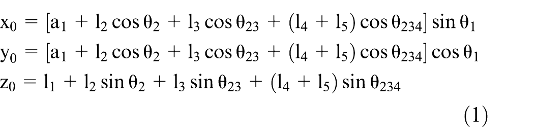
where θ23 [θ23 = θ2 + θ3, θ234 = θ2 + θ3 + θ4] is the angle of the waist, θ2 is the angle of the shoulder, θ3 is the angle of the elbow, θ4 is the angle of the wrist pitch, and θ5 is the angle of the wrist roll. θ234 is the sum of θ2, θ3, and θ4. The kinematic model of the robot is shown in Figure 3. 30

Kinematic model of Mitsubishi RV-2AJ. 30
Dynamics of robot manipulator
It was assumed that there was no friction and additional disruptions. The dynamic model of a n-link manipulator is as follows

where q, T, M(q),

3D model of Mitsubishi RV-2AJ.
If there is a lack of friction or additional disturbances, the joint torques for three joints (Figure 4) can be written as follows
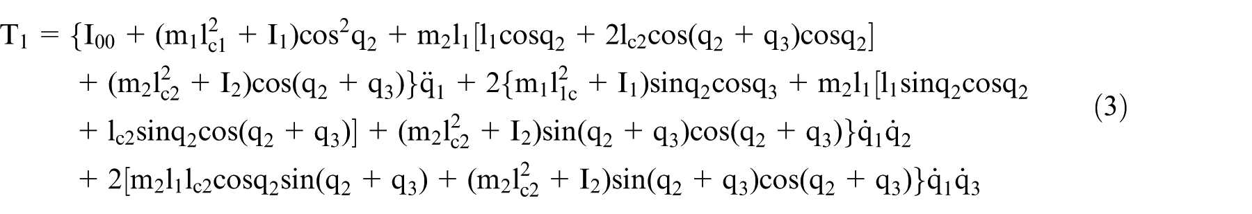
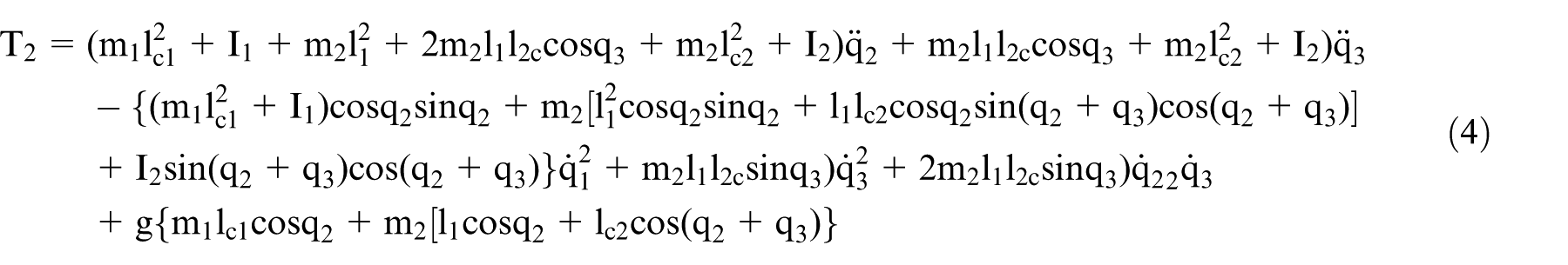

where I00 is the inertial moment of the body base.
Experimental system
In this study, an articulated robot was used for the plasma cutting process. The experimental system, as shown in Figure 5, involves a plasma cutting machine, a robot (MITSUBISHI RV-2AJ) with 5 degrees of freedom, and control hardware and software. The joint motions of the plasma cutting robot were produced by servomotors and a plasma cutting torch was mounted to the robot’s hand using an appropriate apparatus. Movement of the end-effector is accomplished at the X, Y, and Z axes.

(a) Plasma cutting table and (b) plasma cutting robot with cutting torch.
MATLAB software was utilized to determine the cutting trajectory as a function of time. A telecommunication protocol between the computer and experimental system was employed on MATLAB xPC target, and details of the system are given in Figure 6.

MATLAB xPC structure for plasma cutting system.
As shown in Figure 6, the experimental system uses three computers to fulfill its telecommunication needs and control of the robotic system. The system was applied to make necessary modifications on actual data coming from the real system which were transmitted to the host personal computer (PC) to obtain the real-time position error. Both controllers were applied and tested on the plasma cutting robot using MATLAB xPC.
Structure of the standard PID controller and novel controller
The block diagram for the standard PID controller is given in Figure 7(a), where q is actual position data and qd is the desired position value. When the standard PID controller was used for this experimental study, it was unable to obtain perfect results because of system disturbances. A special combination of each constituent of the standard PID controller, which is explained below, was used to develop the novel controller. The novel controller’s structure is shown in Figure 7(b). The proportional part of the control action repeated the change of deviation. The derivative part of the control action added an increment to the manipulated variable so that the proportional plus derivative action was shifted ahead in time. The integral part of the control action added a further increment to the manipulated variable proportional to the area under the deviation line. 31
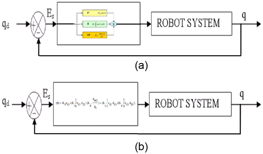
Structure of (a) standard PID controller and (b) novel controller.
The mathematical expression of the novel controller is as follows

where the Kp, Ki, and Kd coefficients were determined with experiments. Both controllers were applied and tested on the plasma cutting robot using MATLAB xPC.
Experimental study
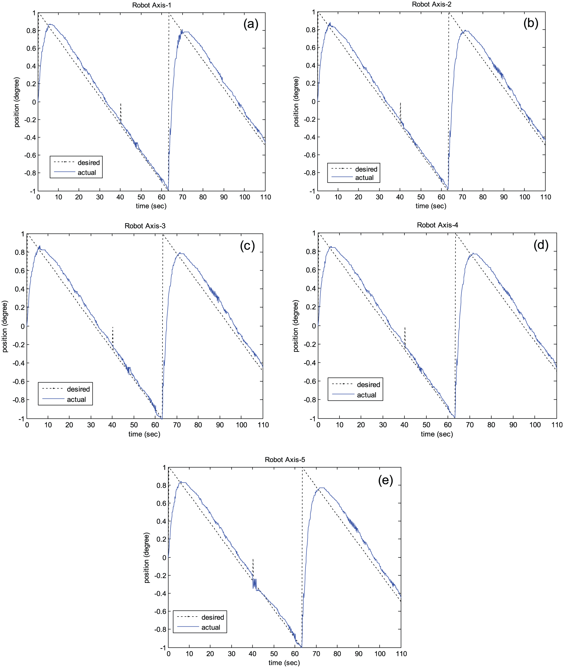
MATLAB-Simulink software was utilized to get the desired position data. All robot axis results were collected on the experimental system for the standard PID controller. A novel controller was proposed using sinusoidal, sawtooth, and square input signals. Figure 8(a)–(e) shows the standard PID controller results for each axis using sinusoidal input.

Standard PID controller’s results for each axis using sinusoidal input.
As given in Figure 9(a)–(e), when the proposed novel controller is used with sinusoidal input on a real-time experimental system, the outputs of the system follow the desired values. It was concluded that these convergences were due to the added integral action of PID controller.

Novel controller’s results for each axis using sinusoidal input.
When sawtooth input is applied on a real-time experimental system, as shown in Figure 10, the results for all axes are not following the desired values. As given in Figure 10(a)–(e), none of robot’s axes can reach peak points. Although the characteristics of the sawtooth signal compared to the sinusoidal signal are not smooth, the results obtained are not good. Figure 11 shows the proposed novel controller’s results for each axis using sawtooth input. The proposed novel controller for the real-time plasma cutting robot mechanism gives better results for the sawtooth input signal on each axis as shown in Figure 11. All the robot’s axes could reach the desired positions. The error value is also much smaller than that of a standard PID controller. Additionally, Figure 12 shows the standard PID controller’s results for each axis using square input and Figure 13 shows the proposed novel controller’s results for each axis using square input, respectively.
Standard PID controller’s results for each axis using sawtooth input.

Novel controller’s results for each axis using sawtooth input.
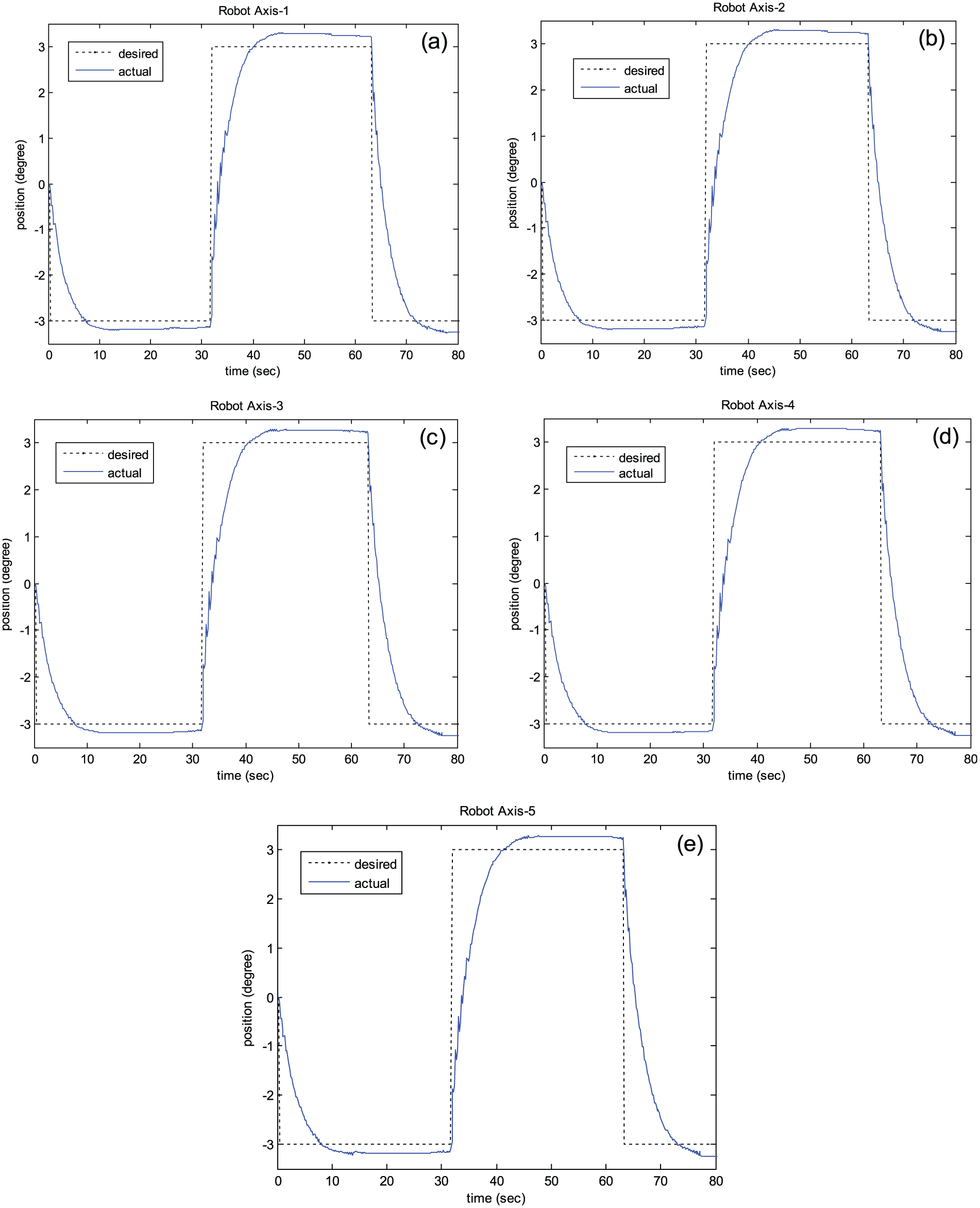
Standard PID controller’s results for each axis using square input.

Novel controller’s results for each axis using square input.
As shown in Figures 12 and 13, when square input is used, the proposed novel controller gives better convergences to the input signal than the standard PID controller. A smaller overshoot value and faster stability can be obtained using the proposed novel controller instead of the standard PID controller.
Conclusion
Real-time control studies in industrial applications have many difficulties. Creating a control system and testing control parameters with this system are the main difficulties of real-time studies. Actually, control systems are usually built at great expense and difficulty. In this study, the MATLAB xPC system was used for the robotic plasma cutting application. The system was built cheaply and easily. All of the nonlinearities, time delays, disturbances, and different controllers (standard PID controller and a novel controller) could be tested on a plasma cutting robot by this system. A novel controller (developed by changing the levels of special effects of the parts of the standard PID controller) was developed to eliminate the disadvantages of the standard PID controller for real-time applications. The two controllers were compared on the plasma cutting robot using xPC. The results show that the proposed novel controller gives perfect solutions for the real-time robotic plasma cutting system. Moreover, the findings of this study indicate that the MATLAB xPC system may be adapted to industrial robotic plasma cutting applications to obtain better results both economically and easily. Hence, researcher believes that the compact inexpensive controllers will be investigated for robotic real-time control systems in the future.
Footnotes
Academic Editor: Jianyong Yao
Declaration of conflicting interests
The author(s) declared no potential conflicts of interest with respect to the research, authorship, and/or publication of this article.
Funding
The author(s) received no financial support for the research, authorship, and/or publication of this article.