
Abstract
Electrostatic field–induced electrolyte jet micro electrical discharge machining depends on heat generated by the periodic pulsed discharge between the workpiece and the electrolyte fine jet from the tip of Taylor cone, induced by the intense electric field, to erode the material from the workpiece. To further investigate the characteristics of this discharge process, with the NaCl solution as the electrostatic field–induced electrolyte jet electrolyte and the silicon wafer as the workpiece, the governing factors of machining polarity, nozzle-to-workpiece distance, voltage applied between positive and negative polarities, and the effect of concentration of the electrolyte on the depth of crater after a single electrostatic field–induced electrolyte jet discharge have been studied. The experimental results show that the average depth of crater increases with the increase in the voltage applied between the nozzle and the workpiece, and increases with the increase in the concentration of the electrolyte, but decreases with the increase in the distance between the nozzle and the workpiece. The results have also demonstrated that the polarity has no clear influence on the average depth of crater after a single discharge.
Keywords
Introduction
Micro electrical discharge machining (EDM) is a non-contact thermal manufacturing process, relying on the discharge between a conductive tool electrode and a workpiece submerged in nonconductive liquid such as kerosene and deionized water to erode the material from substrate material. 1 During the machining, the gap is kept between tool electrode and workpiece, and the pulse power supply is applied in between to generate an intense electric field, leading to a plasma discharge tunnel. The heat generated by the plasma makes the material melt or vaporize from the workpiece. This method is able to machine the conductive material without the restriction of mechanical property such as hardness and brittleness, and moreover, since there is no direct contact between the workpiece and the tool, unlike the conventional method of micro mechanical machining, the hardness of tool electrode is neglectable during micro EDM process. As a result, micro EDM is widely used in micro-hole, micro-pin and micro-component machining. 2
Micro tool electrode machining and micro discharge energy generating are two key factors that inhibited the development of micro EDM. The wire electrical discharge grinding (WEDG) proposed by Masuzawa et al. 3 first makes the online tool electrode machining possible; however, the uneven diameter of the wire and the unsmooth wire surface lead to the non-uniformity of the tool electrode, especially in micro EDM, and moreover the grinding technology results in low machining efficiency. Influenced by Masuzawa et al., 3 many micro tool electrode online grinding methods spring up, such as the block tool electrode grinding and the edge tool electrode grinding, 4 to improve the uniformity of the tool electrode. Electrochemical tool electrode machining 5 and the carbon fiber tool electrode6,7 are proposed to fast fabricate tool electrode to increase the machining efficiency in EDM. Although these tool electrode fabricating methods address part of needs of the tool electrode in EDM, the complication of the machining technique and high cost still exist, and moreover to further decrease the diameter of tool electrode will sharply increase the machining difficulty and cost. As for discharge energy generation method, the existence of stray capacitance 8 inhibits the discharge energy from further decreasing by reducing the capacity in the widely used resistance and capacity (RC) pulse power supply. Even if the methods such as shortening electric feeders, use of electrical insulator for tool electrode holder, and work table materials are adopted, it is still difficult to machine micro rods smaller than 1.0 µm in diameter. 9 The transistor-type pulse generator applies the field effect transistor (FET) to operate the switching on–off in gate control circuit. The duty ratio and pulse current can be changed depending on the request. However, the delay time in discharge occurrence detecting circuit and output signal generating circuit and the power transistor itself 10 makes it difficult to keep the constant discharge duration shorter than several tens of nanoseconds type pulse generator. However, even if future developments of electronics devices can further reduce the delay time existent in transistor-type pulse generator, the discharge energy can never be smaller than the energy stored in the stray capacitance. 11 As a result, the relaxation-type pulse generators are still more preferred in micromachining. 12 As a result, how to further reduce the discharge energy and fabricate micro tool electrode are key problems in micro EDM.
Considering the difficulty of minimum discharge energy generation and micro tool electrode fabrication in EDM, we have proposed an electrostatic field–induced electrolyte jet EDM method. 13 The machining ability of this method and the tool electrode preparation, generation, discharge, and restoration processes have already been verified by several experiments. 14 However, the application and popularization of this method require a thorough study of the effect of machining parameters on this electrostatic field–induced electrolyte jet EDM. An investigation of the governing parameters, including the polarities, electrolyte weight concentration, the nozzle-to-workpiece distance, and the applied voltage, influence on the crater depth after a single electrostatic field–induced electrolyte jet EDM on the surface of the semi-conductive material silicon has been carried out and analyzed. The experimental setup and principle are discussed in section “The experimental platform and principle.” This is followed in section “Results and analysis” by a discussion of the experimental results obtained. A summary is provided in section “Conclusion.”
The experimental platform and principle
The experimental platform of the electrostatic field–induced electrolyte jet micro EDM, shown in Figure 1, consists of a syringe with needle nozzle, a workpiece, a high-voltage direct current (HVDC) power supply, a three-degree (3D) motion platform, and an auxiliary insulating Teflon supporting table. The workpiece, fixed by a conductive clamp on a supporting table, is mounted on a 3D motion platform. The syringe with the nozzle used to store the electrolyte is fixed on an insulated platform. The workpiece and the nozzle are connected to each terminal of the HVDC, respectively. The relative position between the nozzle and the workpiece can be controlled by this 3D motion platform. The electric field intensity can be regulated by the output of the power supply or the gap between the needle nozzle and the workpiece. Contrast to the conventional EDM in the mechanical structure, the pulse generator is replaced by the HVDC power supply instead.

The experimental platform of the electrostatic field–induced electrolyte jet micro electrical discharge machining.
The principle of the electrostatic field–induced electrolyte jet EDM is shown in Figure 2. Since an intense electric field is generated by the HVDC applied between the nozzle and the workpiece in Figure 1, electrolyte stored in the nozzle can be drawn out and form a liquid Taylor Cone at the nozzle outlet with the balance of electric field force and surface tension, as shown in Figure 2(a). As the induced charge accumulating on the surface of the Taylor Cone, the electric field force acted upon the induced charge overwhelming the surface tension of the electrolyte, the tip of the cone ejects a very slim jet. 15 When the jet is near the surface of the workpiece, a dielectric breakdown occurs between the tip of the fine jet and the workpiece, leading to a short-lived plasma channel in between. The heat generated by the plasma rapidly heats the discharge point on the workpiece, leading to the evaporation or scattering of the material, as shown in Figure 2(b). After the discharge, the induced charge neutralized, and the jet stops and the Taylor cone withdraws because the electric field force is smaller than the surface tension, as shown in Figure 2(c), and an extremely tiny crater appears on the workpiece. Soon, under the intense electric field, induced charge restores to form the Taylor Cone again, as shown in Figure 2(a). As a result, the periodic and pulsing electrical discharge process is generated.

Figure depicting a single “discharge cycle” in the E-Jet EDM process: (a) the preparation of the electrostatic field–induced electrolyte jet tool electrode, (b) the discharge process of the electrostatic field–induced electrolyte jet, and (c) the disruption of the electrostatic field–induced electrolyte jet tool electrode.
Contrast to the conventional EDM in tool electrode fabrication, the tool electrode of the electrostatic field-induced electrolyte jet micro EDM has many advantages, such as good uniformity, no tool electrode wear, no online compensation, lower cost, and high efficiency. As for the discharge energy, the energy is generated by pulsed discharge between the induced charge on the tip of the fine jet and the workpiece, which is a new style of discharge energy generation method. The power supply is the HVDC power supply, which is different from the RC or transistor-type pulse power supply in conventional EDM.
Results and analysis
To investigate the effect of parameters on the depth of crater after the E-Jet machining, the silicon wafer has been selected as the workpiece and NaCl electrolyte has been used as the E-jet liquid. After the analysis of the factors, the polarity, the nozzle-to-workpiece distance, gap voltage, and the concentration of the solution have been selected as the input parameters. The depth of crater after a single discharge has been chosen as the response parameter in E-jet EDM. The positive and negative polarity factorial experiments have been designed; the influence of 0.4, 0.6, 0.8, 1.0, and 1.2 mm nozzle-to-workpiece distance on the machining results have been investigated; 1.5, 2.0, 2.5, 3.0, and 3.5 kV have been selected as the original voltage variables to study the effect of machining voltage on the crater; 10%, 15%, 20%, 25%, and 30% NaCl solution have been used to study the effect of electrolyte concentration on the crater depth. The single discharge machining can be completed by the fast feeding and retreating the motion platform under the workpiece. 16 On each sample point, five experiments have been conducted for the factors of distance, voltage, and concentration. The maximum depth and the mean depth of the craters after these five experiments under the same machining environment at each sample point have been measured and calculated. The microstructure images have been acquired using depth-of-field and resolution digital microscope.
The effect of tool polarity on the depth of crater performance
Tool polarity is a key factor that affects the diameter, depth of crater, and tool electrode wear in conventional EDM. The craters machined by a single E-Jet EDM under different polarities are investigated, at 2.5 kV nozzle-to-workpiece voltage, 160 µm inner of the nozzle diameter, 2% wt NaCl electrolyte, and 4 MΩ current-limiting resistance.
As shown in Figure 3, five positive-polarity machining experiments and five negative-polarity machining experiments have been conducted, respectively. After these two-polarity machining experiments, the bottom of the crater is made up of many small tips and caves, shown in Figure 3(a) and (b), and the maximum depth is about 0.9 µm and the mean depth vibrates between 0.45 and 0.5 µm, as shown in Figure 3(c).

The shape and measurement of the depth of crater fabricated by a single E-Jet EDM on the silicon wafer (a) with positive polarity machining, (b) with negative polarity machining, and (c) the comparison of the maximum and average depth of crater under positive and negative polarity machining.
As shown in Figure 3, the average and maximum depth of craters do not have significant changes in the reversed polarity experiments. This is caused by the reason that under the intense electric field, the induced charge opposite to the workpiece in polarity is generated on the surface of Taylor Cone. When the induced charge on the surface overwhelms the Rayleigh limit, a slim fine jet will eject from the tip of Taylor cone. At the time when the fine jet is about to touch the workpiece, the short-lived plasma will generate in between, and the heat generated by the plasma will lead to the melting or vaporization of the material. 13 The random characteristics of ions in the plasma between the tip of the fine jet and workpiece during the discharge result in the tips and caves on the bottom of the crater after a single discharge. When reversing the polarity, the induced charge on the surface of the Taylor cone will reverse. The electrolyte and concentration are invariable during the reversed experiments, resulting in the unchanged density of the induced charge on the surface. Under positive and negative polarities, the NaCl electrolyte can be induced by Na+ and Cl− on the surface of Taylor Cone respectively, and the atomic weight of sodium and chlorine is comparable. As a result, the density of induced charge is almost unchanged, except the opposite polarity in the experiments. Consequently, unlike the conventional EDM, the difference of the crater under reverse polarity does not significantly change, and the polarity change has little effect on the depth of the crater machined by a single E-Jet.
Effect of the nozzle-to-workpiece distance on cater depth
The distance between the positive and negative polarities has a great effect on the discharge in conventional EDM, and the distance control is a main control method in conventional EDM process. As a result, the effect of negative-to-positive polarity distance on the depth of crater after a single E-Jet discharge is investigated, for the voltage between negative-to-positive polarity 2.5 kV, the inner diameter of the nozzle 160 µm, the electrolyte concentration 20%, negative polarity machining, current-limiting resistance 4 MΩ, and negative polarity.
On each definite distance, five experiments have been conducted. As shown in Figure 4, the average depth of crater decreases as the distance between these two polarities increases. However, the maximum depth, about 0.9 µm, does not have clear changes as the increase of the distance in between.
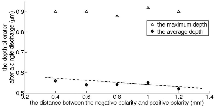
The measurement of the depth of crater fabricated by a single E-Jet EDM on the silicon wafer under negative polarity machining with different nozzle-to-workpiece distance.
During these experiments, the voltage applied is kept invariable, and the distance between these two polarities increases, leading to the decrease in the electric field intensity in between. 17 For the electrolyte concentration does not change, the decrease in the electric field intensity will result in the decline of the density of the induced charge on the surface of the Taylor Cone 18 and on the tip of the fine jet. The decrease in the density of the induced charge on the surface leads to the decrease in the discharge energy per time, and this supports the reason that the average depth decreases with the increase in distance between these two polarities. However, the random characteristics of ions and the inhomogeneous distribution of energy among ions in the plasma between the tip of the fine jet and workpiece lead to the generation of many caves and tips. Although as a whole, the discharge energy decreases as the distance in between increases, the inhomogeneous distribution of energy among ions results in some ions with peak energy, which does not fall rapidly as the whole discharge energy decrease. This might be the reason why the maximum depth of the caves in the bottom of crater is, about 0.9 µm, almost unchanged with the increase in the distance.
When the distance between the nozzle outlet and the workpiece is smaller than 0.4 mm, the continuous discharge is generated and some electrolyte can also be observed on the surface of the workpiece. This is caused by the reason that the intensity of the electric field is so strong that the electrolyte can flow from the nozzle and touched the workpiece directly without E-Jet. When the distance is larger than 1.2 mm, no discharge or E-Jet can be observed. This is because that the electric field is too weak. As a result, too large distance and too small distance are both not preferred in the E-jet EDM process.
Effect of the electrolyte concentration on cater depth
Unlike the conventional EDM, the electrolyte concentration is a new factor, but it is a crucial factor in E-Jet EDM for it affects conductivity, viscosity, and density of the electrolyte. The conductivity and viscosity will influence the formation and E-jet of the Taylor Cone. The influence of the electrolyte concentration on the depth of crater after a single E-Jet EDM is studied, at 1-mm two-polarity distance, 160 µm inner nozzle diameter, 3.0 kV voltage between two polarities, 4 MΩ current-limiting resistance, and negative polarity.
As shown in Figure 5, the average depth of crater after a single discharge increases with the increase in the electrolyte concentration. The maximum depth of the crater does not change under different electrolyte concentration, about 0.9 µm.

The measurement of the depth of crater fabricated by a single E-Jet EDM on the silicon wafer under negative polarity machining with different electrolyte concentration.
The conductivity increases with the increase in electrolyte concentration, leading to free ions or charge increase in the electrolyte. The increase of free ions will result in the increase in the induced charge on the surface of the Taylor Cone, leading to the density of the induced charge on the E-jet.15,17 As a result, when the plasma is generated between the tip of the fine jet and the workpiece, the energy of the plasma will be more powerful as the increase in the density of the induced charge. The increase in the discharge energy will increase the depth of crater per discharge. This supports the conclusion that the depth of crater after a single E-Jet discharge increases with electrolyte concentration. As for the maximum depth during the crater under different electrolyte concentration, although the discharge energy increases with the increase in electrolyte concentration, the random discharge of ions in the plasma generated in between leading to the uneven of the crater bottom and almost unchanged maximum depth after a single E-jet EDM process.
Effect of applied voltage on crater depth
The voltage applied between these two polarities influence on the depth of crater is investigated, at 1 mm distance between these two polarities, 160 µm inner diameter of the nozzle, 20% NaCl electrolyte, 4 MΩ current restriction resistance, and negative polarity machining.
During the experiment, five-level voltage has been selected. At 1.5 kV, the phenomena of E-jet can be observed; however, there is no crater left on the surface of the workpiece, only leaving some electrolyte on the surface. From 2.0 kV on with 0.5 kV in increment to 3.5 kV, the crater is clearly found on the surface. As shown in Figure 6, the average depth of crater increases with the increase in voltage applied; however, the change of voltage applied has no clear relationship with the maximum depth of crater.

The measurement of the depth of the crater fabricated by a single E-Jet EDM on the silicon wafer under negative polarity machining with different voltage applied between the positive and negative polarities.
At the voltage of 1.5 kV, for the voltage is relatively low, leading to weak electric field in between. Although the electric force applied on field-induced charge is larger than the surface tension, the E-Jet can be generated. The low density of the charge resulting in the heat generated between the neutralizing of the induced charge is too small to make the material in the workpiece melt or evaporate, as a result, no crater is found on the workpiece, only leaving some electrolyte. With the increment of the voltage applied, the electric field increases, 17 leading to the increase in the density of the field-induced charge on the E-Jet surface. 18 The increase in the field-induced charge results in the increase in the discharge energy when the plasma is generated between the tip of the fine jet and the workpiece surface, leading to the crater machined by the heat generated by the plasma. During the E-Jet EDM process, the tip of the fine jet is used as tool electrode, and the increase in the energy generated will lead to the increase in the depth of crater. This can support the reason that the average depth increases as the increase in the voltage applied.
However, when the voltage applied is equal or larger than 4.0 kV, the vaporization phenomena has been generated at the outlet of the nozzle, and no E-Jet has been observed between the nozzle and workpiece. This is caused by the reason that the strong repulsive force between the field-induced charge at the tip of the Taylor Cone makes the drops broken before E-Jet is generated, 15 leading to the field-induced charge discharge with the air surrounded other than the workpiece, which has no machining ability. As a result, too large or too small voltage is not preferred in the E-Jet EDM.
From the factorial experiments during the E-Jet machining, we can find the crater after a single E-Jet discharge is mainly affected by the single discharge energy, which is similar to that in conventional EDM. 10 Unlike the conventional EDM, the single discharge energy during the E-jet machining is decided by the induced charge on the tip of the fine jet.
Conclusion
With the electrostatic field–induced electrolyte jet EDM after a single discharge machining, the following conclusions can be drawn:
Unlike the conventional EDM, the polarity has no much influence on the average depth of crater after a single discharge. The experimental results show that under different polarities, at 2.5 kV nozzle-to-workpiece voltage, 160 µm inner of the nozzle diameter, 2% wt NaCl electrolyte, and 4 MΩ current-limiting resistance, the average depth of crater lies between 0.45 and 0.5 µm and the maximum depth vibrates around 0.9 µm.
With the single factorial experiment, the average depth of the crater decreases with the increase in the distance between the nozzle and the workpiece, but increases with the increase in the voltage applied in between; with the increase in the concentration of the electrolyte, the mean depth of the crater after a single discharge will increase. However, the maximum depth of the caves in the bottom of the crater vibrates around 0.9 µm in all these single factorial experiments, and it has no clear relationship with the polarity, voltage applied, distance in between, and the concentration of the electrolyte when the crater is machined on the workpiece.
From the analysis of the factors of the depth of crater after machining, the conclusion that the mean depth of crater after a single electrostatic field–induced electrolyte jet EDM is decided by the density of the induced charge on the surface of the tip of the fine jet can be drawn, and the increase in density of the induced charge will result in the increase in the mean depth of crater.
Footnotes
Academic Editor: Xichun Luo
Declaration of conflicting interests
The author(s) declared no potential conflicts of interest with respect to the research, authorship, and/or publication of this article.
Funding
The author(s) disclosed receipt of the following financial support for the research, authorship, and/or publication of this article: The work is granted by the National Natural Science Foundation of China (NSFC) (Grant No. 51175336), China Scholarship Council (CSC), and Young Researcher Foundation in Shanghai Jiao Tong University (AF0200013).