
Abstract
Electrostatic field–induced electrolyte jet micro electrical discharge machining relies on the cyclic and pulsating electrical discharge between the tip of the fine jet, and the workpiece to remove the debris. To further explore the processing characteristics, the single-pulsating discharge experiments have been carried out with the NaCl electrolyte as the jet solution and the silicon wafer as the workpiece. The experimental results have shown that the crater size after a single electrostatic field–induced electrolyte jet discharge increases with an increase in the voltage applied between the nozzle and the workpiece and increases with an increase in the electrolyte concentration, but declines with an increase in the nozzle-to-workpiece distance. Moreover, the crater size has no direct relationship with the machining polarity, but slightly declines with an increase in the inner diameter of the nozzle. Finally, the conclusion that the parameters which influence the charge density on the electrolyte jet surface can determine the diameter of the single-discharge crater has also been drawn.
Keywords
Introduction
Micro-electrical discharge machining (µ-EDM) is a non-mechanical thermal manufacturing process with which the material is removed by electrical discharges between a workpiece electrode and a tool electrode that are submersed in a dielectric fluid, such as kerosene and deionized water. The high-frequency discharges cause the melt and vaporization of the material on the surface of both electrodes. During the machining, a working gap remains between the tool and the workpiece electrode. A voltage which relies on the working gap and conductivity of the dielectric fluid is applied between these two terminals to generate the intense electric field, resulting in an expanding energetic plasma channel and a current flow after breaking down the dielectric strength of the dielectric fluid. Followed by turning off the current, the melted material is abruptly erupted due to an implosion of the plasma channel. 1 The EDM process is widely used in the machining of hard metals and its alloys in single-part or small batch production. 2
Compared to the conventional micromachining technologies such as etching, deposition and other lithographic techniques, EDM has several substantial advantages:3,4 first, µ-EDM requires a low installation cost and little job overhead compared to lithographic techniques; 5 second, µ-EDM is a flexible method, which makes it ideal for prototypes or small batches of products with a high added value; third, µ-EDM can easily machine complex three-dimensional (3D) shapes, which is proved difficult for etching; 6 finally, µ-EDM is believed to be superior to laser machining in 3D machining and blind holes’ machining. 7 During the µ-EDM, the micro discharge energy per pulse and the scale of the tool electrode are two main factors that influence the machined size.8,9 A lot of research achievements have been obtained on these topics. Foremost, to reduce the discharge crater size, the electrical discharge energy per pulse must be reduced as much as possible. Generally, two kinds of pulse generators are used: relaxation or resistance–capacitance (RC)–type pulse generator 10 and transistor-type pulse generator. 11 Since the relaxation-type pulse generator can generate such small discharge energy simply by minimizing the capacitance in the circuit, it is widely applied in conventional µ-EDM. 12 In theory, the smaller the capacitance, the smaller the discharge energy. If the capacitance is 0, the discharge energy will be infinitesimal. However, in the actual machining, since the stray capacitance lies between the electric feeders, between the tool electrode holder and the work table and between the tool electrode and the workpiece, even if there is no capacitance in the main loop, the existence of the stray capacitance also limits the miniaturization of the discharge energy per pulse.13,14 Although many methods have been developed such as shortening electric feeders, insulating tool electrode holder and insulating work table adopted, it is still difficult to machine micro rods smaller than 1.0 µm in diameter. 15 This is caused by the reason that the stray capacitance cannot be eliminated thoroughly. As for the stay capacitance in the relax pulse generator, some methods have already been tried. In Kunieda et al., 16 the coupled capacitance between the pulse generator and the tool electrode has been introduced to reduce the stray capacity of the system. However, the stray capacity is still difficult to prohibit. Compared with the RC pulse generator, transistor-type pulse generator applies the field effect transistor (FET) to operate the switching on–off of gate control circuit, and therefore, the pulse duration and discharge current can arbitrarily be changed depending on the machining characteristics required. However, due to the delay time in the discharge current detecting circuit and output signal generating circuit and the power transistor itself, 9 it is difficult to keep the constant discharge duration shorter than several tens of nanoseconds using the transistor-type pulse generator. Thus, till now, the relaxation-type pulse generators are still more preferred in micromachining. 17 However, as discussed above, the existence of the stray capacitance still prohibits the micro discharge energy from further decreasing with the relaxation or RC-type pulse generator. Therefore, how to further reduce the micro discharge energy is one of the key problems in µ-EDM.
On the other hand, with the appearance of the wire electro-discharge grinding (WEDG) method, 18 the puzzle of the online tool electrode machining of µ-EDM has been settled and the µ-EDM becomes available. However, due to the uneven diameter of the wire, the burr on the wire surface and the instability of the wire running, the tool electrode manufactured by this method significantly influences the quality of µ-EDM. From then on, many new tool electrode process methods appear, such as the block electrode discharge grinding, the edge electrode discharge grinding, 19 the electrochemical micromachining (ECM) method, 20 the hybrid WEDG and ECM machining method 21 and the carbon fiber tool electrode process method.22,23 Although much progress has been made in the tool electrode fabrication, the problem of high product cost and complicated manufacturing process still limit the wide utility of EDM, especially in µ- or nano-EDM and batch production. Considering these two key problems, the electrostatic field–induced electrolyte jet (E-Jet) EDM has been first proposed in our research. 24 During this E-Jet µ-EDM process, the electrolyte stored in the capillary tube can form a Taylor cone at the outlet of the nozzle when the electric field is applied between the tube and the workpiece. With the increase in the electric field between the nozzle and the workpiece, a very fine jet can be generated from the tip of the Taylor cone, and a cyclic and pulsating electrical discharge can be formed between the tip of the fine jet, and the workpiece to remove the debris from the workpiece. These properties have already been demonstrated by several experiments. However, the stable control of this method and the development of useful applications require a thorough knowledge of the parameters effect on the E-Jet EDM. Therefore, in this work, we report the results of a systematic investigation of the effect of the variation of the governing parameters on the crater inlet diameter on the surface of the semi-conductive material silicon after a single E-Jet EDM. The parameters investigated include the polarities, electrolyte weight concentration, the nozzle-to-workpiece distance, the inner diameter size of the nozzle and the applied voltage.
Experimental setup and procedure
Machining principle
Figure 1 shows the principle of this new E-Jet EDM. In the figure, an intense electric field is applied between a nozzle and a workpiece. Then the electrolyte stored in the nozzle is exposed to an electric field, and the shape of liquid starts to deform from the shape caused by surface tension alone. As the voltage is increased, the effect of the electric field becomes more prominent. As it approaches exerting a similar amount of force on the droplet as the surface tension does, a cone shape begins to form with convex sides and a rounded tip. This approaches the shape of a cone with a whole angle of 98.6° and forms the Taylor cone at the nozzle outlet24,25 (Figure 1(a)). When more and more ions or induced charge are accumulating on the surface of the Taylor Cone, which makes the electric field force overwhelm the surface tension, the tip of the cone emanates a very slim jet. 26 When the jet is about to touch the surface of the workpiece, a dielectric breakdown occurs between the tip of the fine jet and the workpiece because of the intense electric field. This creates a short-lived plasma channel with an electrical discharge that rapidly heats the discharge point on the workpiece, leading to the evaporation or scattering of the material (Figure 1(b)). After each discharge, an extremely tiny crater appears on the workpiece. The cone withdraws from the workpiece to some distance larger than the minimum discharge distance because the loss of the induced charge after the discharge can make the electric force on the jet tip smaller than the surface tension (Figure 1(c)). Then, under the intense electric field, the ions or induced charge will gather again to form the Taylor cone (Figure 1(a)). As a result, the automatic, cyclic and pulsating electrical discharge process can be formed. During each discharge, the tip of the fine jet serves as the tool electrode.
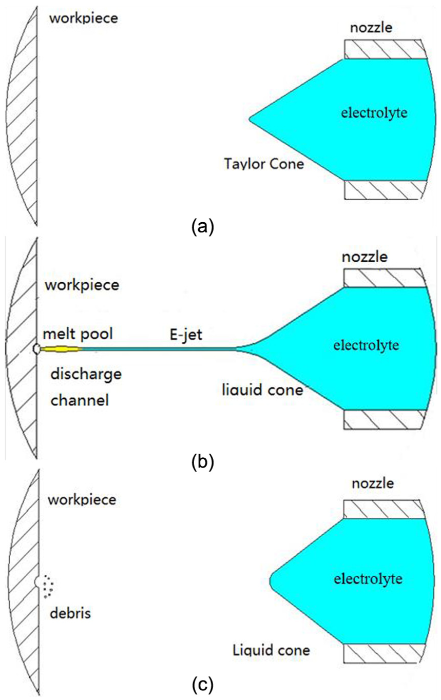
A single “discharge cycle” in the E-Jet EDM process: (a) the preparation of the E-Jet tool electrode, (b) the discharge process of the E-Jet and (c) the disruption of the E-Jet tool electrode.
Different from the relaxation generator, with the intense electric field between the tip of the fine jet and the workpiece exceeding the dielectric strength of the atmosphere, an oscillating discharge is released. This is a new kind of micro tool electrode and micro discharge energy generation method. Discharge current depends on the value of the charge density at the tip of the fine jet. Additionally, the pulse frequency depends on the gathering speed of charge at the tip of the fine jet. Contrasted to the tool electrode in conventional EDM, the tip of the fine jet serves as the tool electrode, and this tool electrode can generate spontaneously without the complex preparation process. Moreover, the electrolyte is salt water solution, which is cheaper than the traditional tool electrode material in EDM such as tungsten and copper. 27
Experimental setup
Figure 2 shows an outline of the machining equipment made for this method. As shown in Figure 2(a), the E-Jet EDM system is composed of a syringe with needle nozzle, a workpiece, a high-voltage direct current (HVDC) power supply, a three-axis motion platform and an auxiliary insulating supporting table. The workpiece is connected to one terminal of the power supply. The nozzle is linked to the other terminal. The syringe and the nozzle used to store the electrolyte are mounted on the insulated platform and the workpiece is placed on a three-axis motion platform. The relative position between the nozzle and the workpiece can be controlled by this motion platform. The electric field intensity can be controlled by regulating the output of the power supply or changing the gap width between the needle nozzle and the workpiece. The relative position of the nozzle to the workpiece can be seen in the partial view of the experimental platform in Figure 2(b). Compared to the conventional electrical machining in the mechanical structure of the platform, there is no pump in the system to generate the pressure on the liquid inside the nozzle, 28 and the pulse generator is replaced by the DC power supply instead.
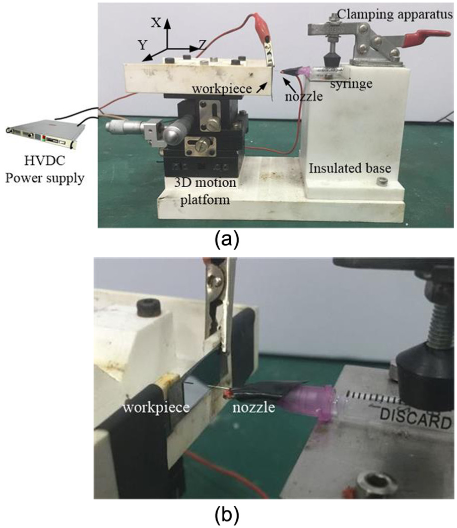
(a) The whole experimental platform and (b) the partial view of the experimental platform of the E-Jet EDM.
Experimental procedure
In this study, the silicon wafer has been selected as the workpiece. The basic parameters of the workpiece are shown in Table 1. NaCl electrolyte has been used as the E-jet liquid to generate the tool electrode. Due to the importance of the factors, the polarity, the diameter of the nozzle, the nozzle-to-workpiece distance, gap voltage and the concentration of the solution have been selected as the input electrical process parameters. The inlet diameter of the crater after a single discharge has been chosen as the response parameter in EDM process.
The basic parameters of the silicon workpiece.
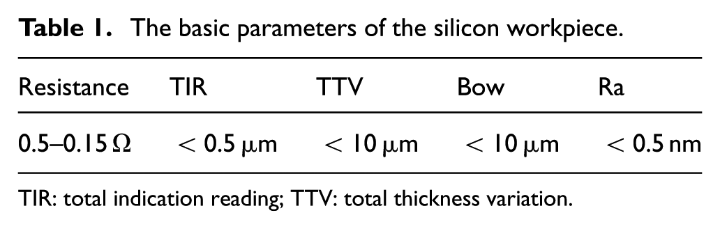
TIR: total indication reading; TTV: total thickness variation.
Unlike the conventional µ-EDM relying on the pulse power supply to complete the periodic discharge, the E-Jet micro machining process is the automatic pulsating discharge process and the high discharge frequency is mainly decided by the electric field applied and the electrolyte concentration selected. As a result, the single discharge in the E-Jet machining cannot be easily finished by adjusting the frequency of the pulse power supply as the conventional µ-EDM, but can be completed by abruptly feeding and retreating the motion platform under the workpiece related to the nozzle in a very short time to change the electric field in between. 24 All the experiments in micro E-Jet EDM process have been conducted by a high-voltage power supply instead of conventional transistor pulse generator or the relax generator.
After a single spark between the tip of the fine jet and the workpiece, the inlet diameter of the crater has been measured. These values have been calculated on the basis of average value method. The microstructure images have been acquired using scanning electron microscope (SEM), and the values of the inlet diameter of the craters are measured using large depth-of-field and high-resolution digital microscope.
Results and discussions
The effect of tool polarity on the process performance
Tool polarity is a primary factor that affects the process performance such as the crater diameter, crater depth and tool electrode wear in conventional EDM. The effect of different tool polarities on the process performance of E-Jet µ-EDM is given in Figure 3, for the nozzle-to-workpiece voltage of 2.5 kV, the inner of the nozzle diameter of 160 µm, 2% wt NaCl electrolyte and 4 mΩ current-limiting resistance. The craters with positive and negative tool polarities are given in Figure 3(a) and (b), respectively. The diameters of the crater in positive and negative are around 3.9 and 3.7 µm, respectively. These craters after different tool polarities are surrounded with a circular recast layer embossment, and some spherical particles are scattered on the bottom of the crater surface. Comparing the similarity of the topology of the crater machined to the crater processed by the conventional µ-EDM in Ji et al., 29 it can be found that the crater structure after a single E-Jet discharge is a typical structure machined by EDM process. The effect of the positive and reversed polarity on the crater diameter is illustrated in Figure 4. There is no clear corresponding change in the diameter of the crater when the sign of the polarity is reversed.
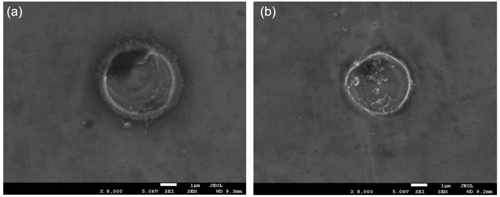
The images captured using SEM to investigate the effect of tool polarity on the process performance in (a) the positive polarity EDM process and (b) the negative polarity EDM process.
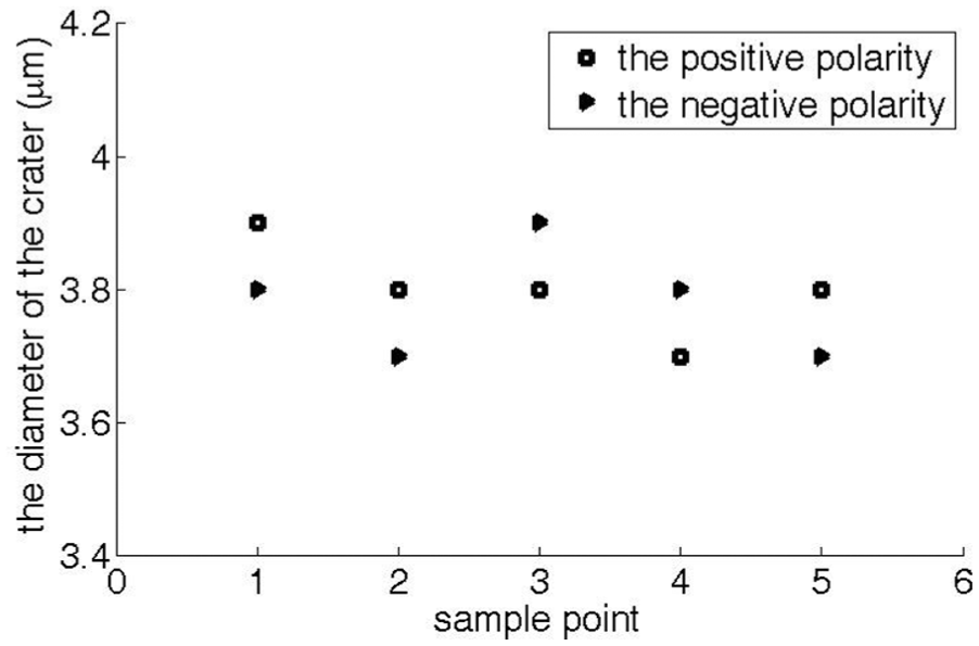
The effect of the positive and reversed polarity on the diameter of the crater machined by E-Jet single-discharge machining.
There are many reasons causing these phenomena. During the machining, as the charge induced on the surface of the Taylor cone is opposite in polarity to the workpiece accumulating, the charge carried on the surface of Taylor cone gradually outweighs “Rayleigh limit,” and then the slim jet ejects from the tip of the cone. When the jet is about to contact the workpiece, the intensity of electric field between the tip of the jet and the workpiece is large enough to generate a short-lived plasma channel with an electrical discharge leading to the removal of the material from the workpiece. The circular recast layer embossment and the spherical particle are the stacking of the base material, as shown in Figure 3(a) and (b). This is caused by the heated material scatter after the discharge, and the spherical particle is the product of the heated material after precipitate, 29 which is a typical phenomenon in the EDM process.
As for Figure 4, if the polarity between the workpiece and the nozzle is reversed, the accumulation of the sign of the charge in the liquid is reversed. For each Na+ or Cl− ion has one charge, the ion concentration and the charge density do not change during the reversed polarity experiment. Moreover, contrasted to large mass difference between the electrons and positive charged particles in the conventional EDM, 30 there is smaller difference of mass between Cl− and Na+ ions in the E-Jet EDM process. In conventional µ-EDM, the smaller mass of electrons will have larger acceleration and larger velocity than the heavier mass of positive charged particles in a very short discharge period. The energy delivered by the electrons to the positive polarity is by far larger than that transferred by the positive charged particles to the negative part. As a result, the positive polarity will have more energy than the negative one, which leads to the larger craters in the positive polarity. However, in the E-Jet discharge machining process, for the smaller difference of the mass between the positive ions and negative ions, there is small difference of the craters machined by the positive and negative polarity machining in E-jet single-discharge machining process. This leads to the phenomena that the diameter of the crater after a single discharge does not change with the reverse of polarity. This supports the theory that the change in polarity has a little influence on the inlet diameter of the crater under E-jet single discharge.
Effect of the nozzle inner diameter on the crater size
The effect of the nozzle inner diameter on the crater diameter is illustrated in Figure 5, for the input voltage of 2.5 kV, 4 mΩ current-limiting resistance, the 20% wt NaCl electrolyte and negative tool polarity; 60, 110, 160, 210 and 260 µm have been chosen as the inner diameter of the nozzle.
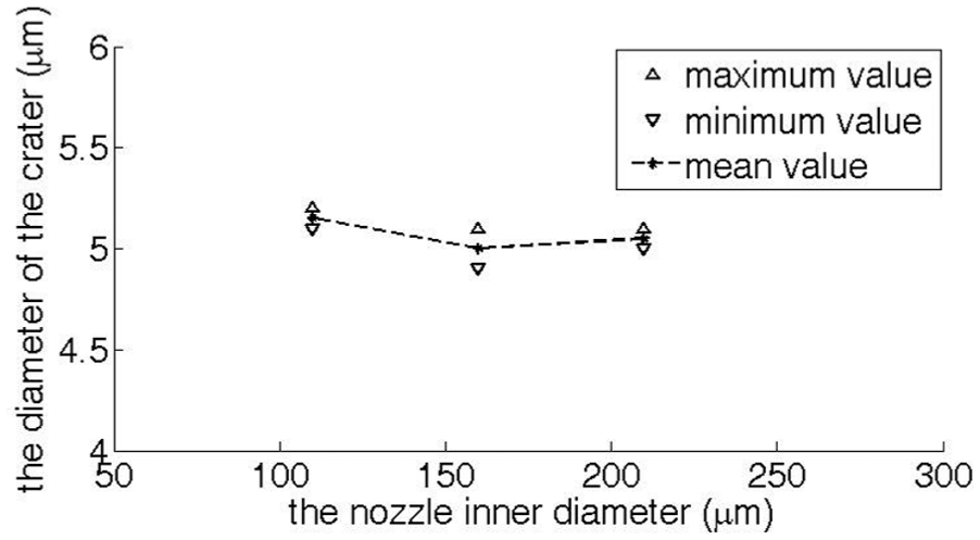
The effect of the nozzle inner diameter on the diameter of the crater machined by the E-Jet single-discharge machining.
During the experiments, when the inner diameter of the nozzle is 60 µm, the electrolyte jet can disperse into ion gas shortly after its ejecting from the nozzle, and the spark does not generate on the workpiece but with the air, thus leading to no crater on the workpiece. When the nozzle inner diameter is 260 µm, although the electrolyte jet reaches the workpiece and a weak spark is generated on the workpiece, there is also no crater created on the workpiece, only leaving some electrolyte on the spark point. The crater diameters measured when the inner diameters of the nozzle are 110, 160 and 210 µm are shown in Figure 5. It can be found that the crater diameter declines very slightly with the increase in the inner diameter of the nozzle.
This phenomenon can be explained as follows. The intense electric field at the outlet of the smaller inner diameter of the nozzle results in the higher charge density at the Taylor cone, leading to the surface charge repulsion by far overwhelming the surface tension. 31 Therefore, the jet scatters into gas with ions, resulting in the ions discharging with the air before reaching the workpiece. This causes the phenomena of no craters on the workpiece at 60 µm in nozzle inner diameter. However, the intensity of electric field decreases at 260 µm in nozzle inner diameter compared to that at 60 µm, leading to the decrease in the charge density. 31 At this point, although the electrolyte jet can be formed and the discharge can be generated on the workpiece, the discharge energy is too weak to create craters on the workpiece. While the inner diameter of the nozzle is at 110, 160 and 210 µm, the diameter of the crater has a very slight decline with the increase in the size of the nozzle. At these ranges, according to the Taylor cone hold electric field theory in Rohner et al., 32 the electric field intensity slowly decreases with the increase in the size of the nozzle, leading to a very slight decrease in charge density during the increase in the inner diameter of the nozzle. This supports the theory that the diameter of these caters only slight decreases when the nozzle inner diameter changes from 110 to 160 and 210 µm.
Moreover, when selecting the size of nozzle, too large or too small nozzle can also lead to some other problems. Too large size of the diameter of the nozzle will lead to a high initial start voltage and keeping voltage; on the contrary, the problem of clog caused by the small solid particles in the electrolyte might occur if the inner diameter of the nozzle is selected too small, which will result in the interrupt of the E-Jet micro electric discharge machining might appear.
Effect of the nozzle-to-workpiece distance on the process performance
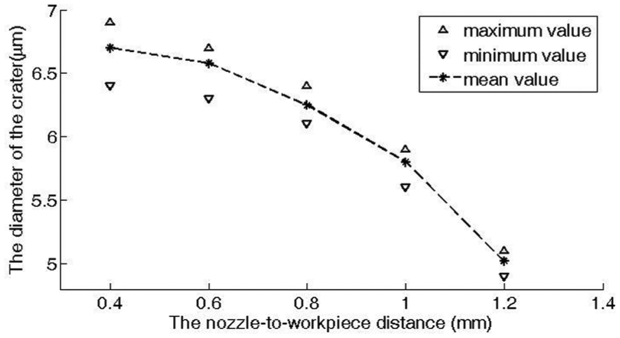
The influence of the nozzle-to-workpiece distance on the performance of the diameter of the single-discharge machining crater is shown in Figure 6, for the two-terminal polarity voltage of 2.5 kV, the inner of the nozzle diameter of 160 µm, 20% wt NaCl electrolyte, 4 mΩ current-limiting resistance and negative tool polarity; 0.4, 0.6, 0.8, 1.0 and 1.2 mm nozzle-to-workpiece distances have been used to denote the spark gap.
The effect of the nozzle-to-workpiece distance on the diameter of the crater machined by the E-Jet single-discharge machining.
It can be seen from Figure 6 that the crater diameter decreases sharply with an increase in the nozzle-to-workpiece distance. During the experiments, with the stable control voltage between the two polarities, as the nozzle-to-workpiece distance increases, the electric field intensity in between will decrease, 33 leading to the decrease in the charge density of the jet. 34 The decrease in the charge density will result in the decrease in the discharge energy per time. As for the jet diameter, the decrease in the charge density with the increase in the nozzle-to-workpiece distance causes the decrease in the electric field stress, leading to the increase in the diameter of the electrolyte jet. 34 Although the diameter of the E-jet increases with the increase in the nozzle-to-workpiece distance, we can find that the diameter of the crater after a single E-jet discharge still declines with the increase in the nozzle-to-workpiece distance in Figure 6. This is because that the discharge is generated between the tip of fine jet and the workpiece, and according to the theory of the tip discharge, the size of discharge part at the tip of the fine jet does not change along with the increase or decrease in the E-jet diameter during a single discharge. From the observations and analysis, it can be found that the diameter of the crater drops with the decline in the discharge energy and has little direct relationship with the diameter of the fine jet during E-jet single-discharge machining for the tip of the fine jet, it is used as the tool electrode in E-jet discharge machining and it is almost unchanged at different distances between the nozzle and the workpiece. These experimental results support that it is the single micro discharge energy between the tip of the fine jet and the workpiece that determines the diameter of the crater after a single E-jet electrical discharge, which coincides with the conclusion in conventional EDM that the discharge energy mainly determines the crater size.35,36
Effect of applied voltage on the process performance
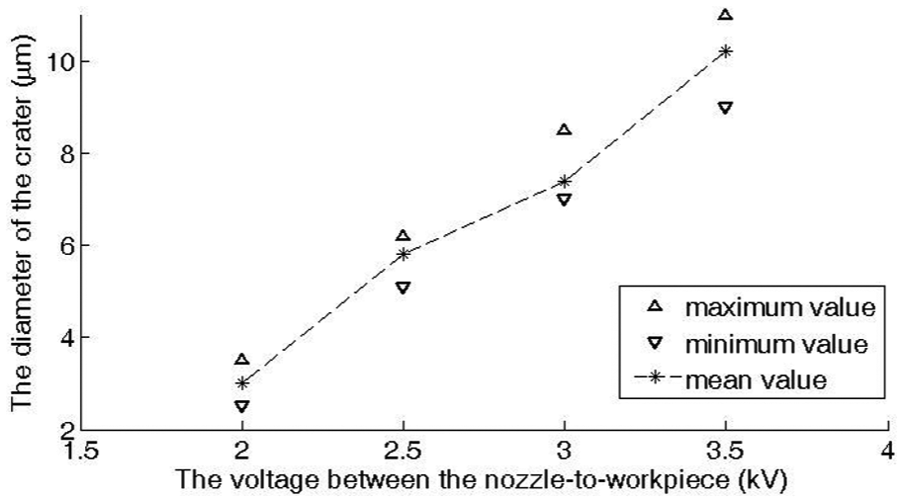
The influence of the voltage on the crater diameter after a single discharge is shown in Figure 7, for the nozzle-to-workpiece distance of 1 mm, the inner of the nozzle diameter of 160 µm, 20% wt NaCl electrolyte, 4 mΩ current-limiting resistance and negative tool polarity.
The effect of the voltage between the nozzle and workpiece on the diameter of the crater machined by the E-Jet single-discharge machining.
During the experiments, five different voltages, 1.5, 2.0, 2.5, 3.0 and 3.5 kV, have been applied between the nozzle and the workpiece. When the voltage is set at 1.5 kV, although the jet has been observed, no crater has been created at all, and only some electrolyte has been left on the surface of the workpiece after a spark. When the voltage changes from 2.0 to 3.5 kV, the typical crater can be created on the workpiece. It can be seen from Figure 7 that the crater size increases sharply with the increase in the voltage applied. This phenomenon can be explained as follows. At first, when the voltage applied is very small, the electric field is also very weak. If the electric force of the induced charge on the surface of the jet is larger than the surface tension force, the jet can be formed. However, if the discharge energy between the tip of the jet and the workpiece is not large enough to generate the heat to melt the material on the workpiece, the crater is not left on the workpiece. With the increase in the voltage applied, the electric field intensity will increase accordingly, 33 resulting in the increase in induced charge on the Taylor cone, and therefore leading to the increase in micro discharge energy during the single discharge; as a result, the crater is generated when the discharge energy between the fine jet and the workpiece is large enough to make the material melt or vaporized from the workpiece. 34 During the experiments, the crater diameter increases with the increase in the applied voltage. However, with the increase in voltage, the E-jet diameter will decrease. 35 This is because the increase in the voltage applied results in the increase in the electric field, leading to an increase in the charge density on the surface of Taylor cone. The charge density increases on the cone will cause a sharper angle at the tip part of the cone driven by the electrostatic field stress. Then, the sharper angle at the tip leads to the smaller cross section and smaller diameter of the E-Jet near the tip with large charge density. Similar to the discussions in section “Effect of the nozzle-to-workpiece distance on the process performance,” for the tip discharge theory and the feature of the unchanged shape of the tip of the fine jet during the E-jet discharge machining, it reconfirms that the micro discharge energy determines the crater size in a single E-jet discharge machining process. This also coincides with the description that the factors which determine the limits the miniaturization in µ-EDM may be the electrical discharge energy of each pulsating discharge.35,36
Moreover, it should be mentioned that the increase in the voltage applied also results in an increase in the frequency of the discharge. However, when the voltage is larger than 4 kV, the liquid scatters at the nozzle outlet and the jet cannot be formed. These phenomena are caused by the surface charge repulsion gradually overwhelming the surface tension with the increase in the electric field, leading to the break down of the electrolyte before reaching the surface of the workpiece and discharging with the air.
Effect of the concentration of solution on the process performance
The concentrations of the solution will affect the viscosity and conductivity of the solution. The formation theory of the Taylor cone has determined that the viscosity and conductivity of the solution will have a huge impact on the Taylor cone and jets emission. 37 Therefore, the concentration of the solution is also one of the most important factors in the E-jet µ-EDM process. Figure 8 shows the influence of the concentration of the electrolyte on the crater machined by the E-Jet single-discharge machining, for the nozzle-to-workpiece distance of 1 mm, the inner of the nozzle diameter of 160, 10% wt, 20% wt and 30% wt NaCl electrolyte, two-terminal polarity voltage of 3.0 kV, 4 mΩ current-limiting resistance and negative tool polarity.
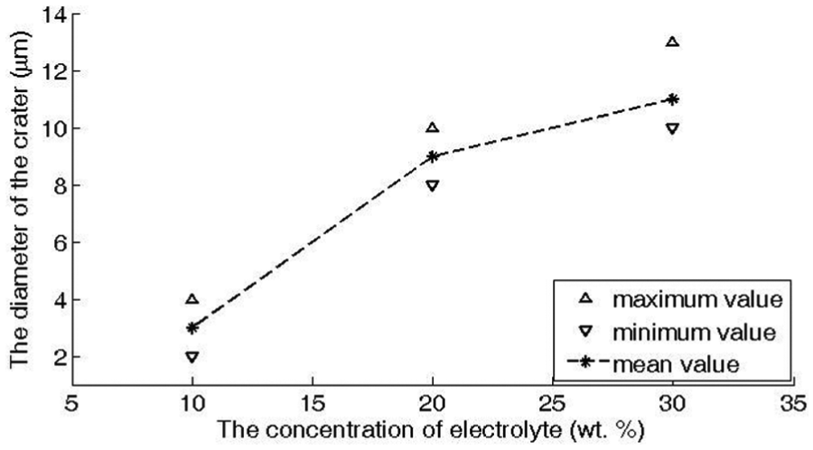
The effect of the electrolyte concentration on the diameter of the crater machined by the E-Jet single-discharge machining.
It can be seen from Figure 8 that the crater size increases with the increase in the concentration of the electrolyte. This phenomenon can be explained as follows. The induced charge in the jet is dependent on the conductivity of the solution which is directly related to the ion concentration, and the increase in ion concentration will result in the increase in the charge density under the intense electric field. The experiments in electrospinning have suggested that as the charge density increases, the cone will adopt a steeper angle caused by the electrostatic field stress. 35 With a steeper angle at the tip of the jet, there will be a smaller cross section near the tip of the fine jet. As a result, the increase in the concentration of the electrolyte results in the decrease in the cross section and the decrease in the diameter of the jet near the tip. However, the induced charge on the tip of the fine jet will generate more discharge energy with the increase in the ion concentration, which leads to the larger diameter of the crater left on the workpiece. That the micro discharge energy affects the miniaturization in µ-EDM can explain the reasons why the crater size machined by the E-Jet after a single discharge increases with concentration of the electrolyte of the jet.35,36
Conclusion
This article focuses on revealing the influencing factors on the crater inlet diameter after a single E-Jet micro electrical discharge machining, and the following conclusions can be drawn:
From craters machined by the E-Jet micro electrical machining under different polarities, the experimental results show that the change in polarity has little effect on the diameter of the crater.
For the single-discharge crater diameter, the inlet diameter of the crater declines slightly with the increase in the nozzle diameter. However, too large nozzle can lead to weak discharge energy without the machining ability while too small nozzle results in the E-jet discharging with air instead of the workpiece.
For the single-factor influence on the diameter of the single-discharge crater machined by E-Jet µ-EDM, the inlet diameter of the crater increases with the increase in the voltage applied between the two-polarity and increases along with the increase in the electrolyte concentration, but decreases with the increase in the distance of the nozzle-to-workpiece.
For the decisional factors on the crater diameter machined by the E-Jet single-discharge machining, the parameters which can increase the charge density on the electrolyte jet surface play important roles in the increase in the diameter of the single-discharge crater.
Footnotes
Declaration of conflicting interests
The author(s) declared no potential conflicts of interest with respect to the research, authorship and/or publication of this article.
Funding
The author(s) disclosed receipt of the following financial support for the research, authorship, and/or publication of this article: The work was granted by the National Natural Science Foundation of China (NSFC; grant no. 51175336), China Scholarship Council (CSC) and Young Researcher Foundation in Shanghai Jiao Tong University (SJTU).