
Abstract
In the process of the robot practical working, the change of motion direction of trajectory is inevitable. When the direction changes dramatically, the sharp angle between adjacent trajectories, which can generate the vibration of robot, affects the service life of the robot. In order to deal with the sharp angle between adjacent trajectories, we propose a method which can deal with the sharp angle transferring by inserting transition arc, which is called position level, to solve the trajectory speed control problem. We analyze three basic analytic trajectories—space line, space arc, and space parabola—and present the formula for calculating the parameters of circular-arc-related parameters and propose the implementation process of algorithm of robot system. Through the simulation and experiment, this method can solve the sharp angle trajectory transfer problem effectively, increase the transfer speed dramatically, and reduce the vibration of robot’s mechanical structure.
Introduction
With an increasing demand for robots in the industrial applications, the motion planning for robots becomes more and more important; the smooth continuous movements of robots play an important role in improving the kinematic accuracy and kinematic stability of robots, which is the key to achieve high-accurate and high-speed robotic movement. Especially for palletizing robot, high speed (operating speed >1.5 m/s) and smooth transfer of robot motion trajectory means an efficient work.
The motion planning for robots can be divided into path planning and trajectory optimization. The most common used path planning method is getting the operating robots’ position and pose by teaching and by showing, and then develop the motion trail of the robot by interpolation. In the industrial practice, we found that the change of robots’ trajectory direction during huge trajectory will lead to the vibration of the structure of robots, which may exacerbate the wear of the structure and cause bad influence on the robots’ kinematic accuracy and service life. The factor that causes the mechanical vibration is the angle between the transition points of the trajectory, which is called the sharp angle. Sharp angle hampers the robots’ speed continuity and trajectory continuity. Therefore, eliminating the sharp angle during huge trajectory motion of robot is important for the great robot’s motion.
The robot’s path planning is in the joint space and Cartesian space. Tondu and Zorkany 1 presented a method of time optimal trajectory planning, with which a smooth transition of straight line is used to connect the key point in robot’s joint space; Bazaz and Tondu 2 used cubic spline curve to connect the key point in joint space, but ignored the continuation of acceleration in transition points of the trajectory; Zha 3 used the Bezier curve, taking the ruled which is made up of position vector as the trajectory of robot. In path planning, the most widely used method is piecewise polynomial. Xu and Ma 4 used the 3-5-3 spline function for the trajectory planning of robot; Zhuang and Yao 5 put forward a method based on the law of motion of the cycloid; Ren and Sun 6 proposed a method based on spline curve generating principle and screw theory in Cartesian space trajectory planning method. All these path planning methods are used to get a smooth, continuous path curve to ensure high-accurate and high-speed robotic movement.
In computer numerical control (CNC) machining, the experts did a lot of research in the field of achieving high speed, smooth transfer of trajectory. In Ye and Zhao, 7 a method of machining error control switching speed, on the premise of meet the error precision, realized the ascension of switching speed. And Yang et al., 8 based on Ye and Zhao, 7 analyzed that the situation of the sharp angle is an obtuse angle, which is the algorithm’s actual operation. Zhi et al. 9 and He and Luo, 10 respectively, inserted the Hermite curve and transition vector to fit the trajectory near transition point, but the algorithm is complex and limited by machining error. Lv et al. 11 proposed the insert-the-transition-arc method, and due to the limitation of processing error, it is difficult to be widely used.
This article combines the research results of robot path planning and high speed, smooth transfer of trajectory in the process of CNC processing and proposes a new approach—position-level (PL) approach. PL approach inserts a transition arc in robotic huge trajectory motion, achieving speedy and smooth transfer during the robotic trajectories. Section “PL Approach” summarizes the raising of PL approach. Sections “Basic trajectory transfer situation,”“Parameter calculation,”“Calculate the position of PL point,” and “Calculate the pose of PL point” describe the calculation of parameters of the PL approach between straight line, arc, and parabola in detail. Based on the actual situation, sections “Adaptive adjustment of the PL Position Degree Length” and “Implementation of PL approach in robot system” present the adaptive adjustment process of the PL Position Degree Length; sections “Adaptive adjustment of the PL Position Degree Length” and “Implementation of PL approach in robot system” also show the realization process of the PL approach in the robotic system. Sections “Simulation” and “Conclusion” give the implementation results and conclusions for PL approach used in practical robots.
PL approach
Figure 1 shows the simple case of trajectory transfer between two linear trajectories.

Turning between two linear trajectories.
Let

where
Figure 2 shows the correlation of the angle between trajectories

Correlation of the angle between trajectories and the turning velocity variation at the turning point of the robot end-effector.
It is shown in Figure 2 that a low value of
The large velocity variation increases the robot’s structural vibration. In order to decrease the velocity variation at the turning point, deceleration of turning velocity v1 and increase in turning angle are introduced when the acceleration and interpolation period of robot are constant. However, low speed reduces the productivity of robot and frequent speed changes increase the wear and tear of the mechanical structure. Conversely, a large angle between trajectories provides lower velocity vibration and avoids frequent velocity changes, and the robot can efficiently achieve its task.
In order to increase the angle between trajectories and decrease velocity vibration, a novel method named PL is presented.
PL approach. For simplification, let us assume there are two straight line trajectories

Two-linear trajectory transfer.
Basic trajectory transfer situation
The typical trajectory of industrial robots is line, circle and parabola. There are nine kinds of transferring trajectory conditions between two different consecutive paths, as shown in Figure 4.

Situation of robot trajectory transfer: (a) line–line, (b) line–circle, (c) line–parabola, (d) circle–line, (e) circle–circle, (f) circle–parabola, (g) parabola–line, (h) parabola–circle, and (i) parabola–parabola.
Parameter calculation
In order to generate the arc trajectory MN, we need to know the coordinates of points M and N, center coordinates, radius, central angle, and arc length of arc MN, solving steps as follows:
Step 1. Points M, N, and P2 generate a plane, and through the rotation matrix, rotate plane MP2
N to plane xoy, and then get the coordinates of three points in plane xoy, which are as follows:
Step 2. OM and

Step 3. On the basis of step 2, we can get the radius (R) using equation (3)

Step 4. Using the cosine law, obtain the central angle of arc

Step 5. Based on steps 3 and 4, the arc length of arc

Step 6. Calculate the central angle of points M,
According to the above steps, we know that to get the interpolation information of arc MN, the key is to get the coordinates of points M and N. The following will be derived for solving the formula of coordinates of points M and N in detail.
Calculation of the position of PL point
PL point in linear trajectory
As shown in Figure 5, we can calculate the position of point

PL point in linear trajectory.
Step 1. Calculate the length of
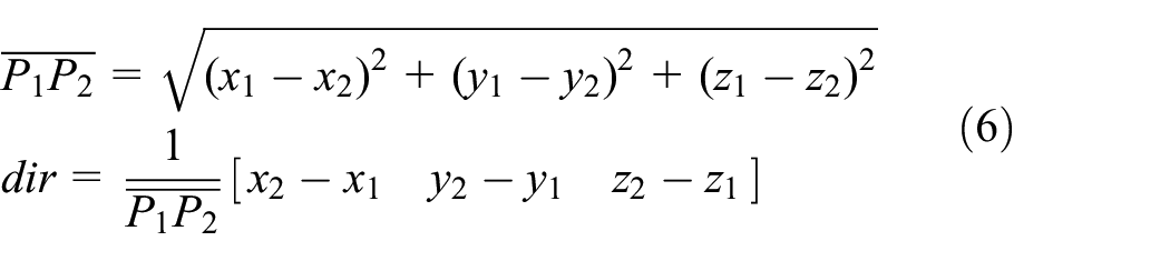
Step 2. Calculate the position of point

PL point in circle trajectory
Figure 6 shows the case in which PL point is inserted in circle trajectory; we can get the position of point

PL point in circle trajectory.
Step 1. Calculate the relevant parameters of arc
Step 2. Through equation (8), calculate the central angle
Step 3. On the basis of step 2, we can obtain the coordinates of point M in plane
Arc

Arc

Step 4. Transform point
PL point in parabola trajectory
As shown in Figure 7, Through steps 1–4, we can obtain the coordinates of point

PL point in parabola trajectory.
Step 1. Calculate the parabolic equation (
Step 2. Through equation (10), calculate the increment in x-axis of chord length

Step 3. On the basis of step 2, we can obtain the coordinates of point M in plane
Ratio ≥ 0

Ratio ≤ 0

Step 4. Transform point
Calculation of the pose of PL point
As it is known to all, the motion of the robot needs to know not only the position of the end-effector but also the pose of the end-effector. In linear trajectory transfer case, by the concept of the equivalent axis and angle, the pose of PL point is given as follows:
Step 1. Based on the pose and position matrix of start point

Step 2. The equivalent axis (f) and angle (θ)


Step 3. The equivalent axis (f1) and angle (θ1) of point M

Step 4. Calculate the pose matrix of point M.
Adaptive adjustment of the PL Position Degree Length
The start and target positions of the robot’s movement have been determined, so the displacement of trajectory is determined, and the PL Position Degree Length is limited by the displacement of adjacent trajectory. Assuming that the displacement of trajectory 1 is l1 and trajectory 2 is l2, the value of l1 and l2 in different trajectories is shown in Figure 8, and the adaptive adjustment determining process of the PL Position Degree Length is shown in Figure 9.

Value of l1 and l2 in different trajectories.
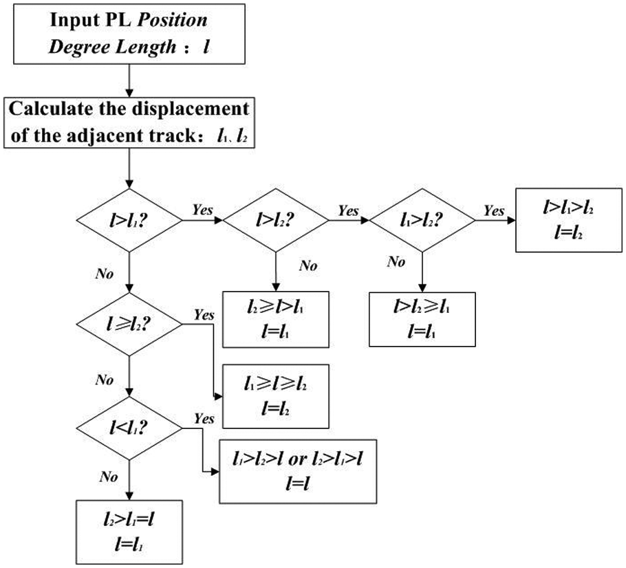
Adaptive adjustment determining process of the PL Position Degree Length.
Implementation of PL approach in robot system
In robot system, the PL Position Degree Length and the starting point, mid-point, and target point of trajectory are preset parameters. In robot practical working, according to the coordinates of trajectory, selected each point generated trajectory types, and adjust PL Position Degree Length, based on the actual situation, choosing the right formula from equations (2)–(17), calculating relevant parameters, through the inverse kinematics of robot to obtain joint variables, driving the robot movement. The specific implementation process is shown in Figure 10.

Implementation process of PL approach.
Simulation
MATLAB numerical simulation
Set the initial value of PL Position Degree Length: l = 300 mm, get the schematic diagram of nine basic situations of robot trajectory transfer. The results of numerical simulation are shown in Figure 11.

Results of numerical simulation: (a) line–line, (b) line–circle, (c) line–parabola, (d) circle–line, (e) circle–circle, (f) circle–parabola, (g) parabola–line, (h) parabola–circle, and (i) parabola–parabola.
Implementation of PL approach in robot system
The experimental system platform which comprises 4-degree-of-freedom palletizing robot, teaching box and control cabinet, and the robot structure is made up of two shifting pairs and two revolute joints as shown in Figure 12.

Four-degree-of-freedom palletizing robot experiment platform.
In the experiment, PL approach is integrated into the robot system, and a series of points of pallet task trajectory are given as shown in Table 1, and preset the value of PL Position Degree Length. Figure 13(a) shows the trajectory before applying the PL approach, and Figure 13(b) shows the trajectory after applying the PL approach.
Parameter of experiment.


Results of 4-degree-of-freedom palletizing robot experiment: (a) before and (b) after.
In terms of the figure of speed near the turning point (Figure 14), we found that the change trend near the turning point becomes smooth after applying the PL approach than before. Reducing speed direction changed dramatically, increasing the continuity and stability of the robot trajectory.
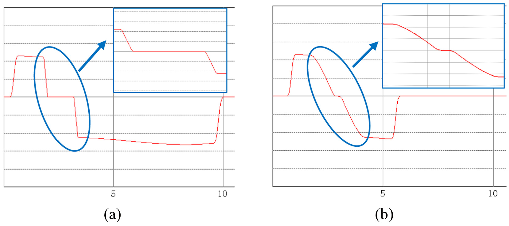
Figure of speed near the turning point: (a) before and (b) after.
In the motor control of the robot, the vibration of the robot’s mechanical structure as an external signal affects the output of the motor torque, so the torque command is used to characterize the degree of vibration of the robot’s mechanical structure. A frequent change in torque command means a more severe vibration. As shown in Figure 15, we can draw a conclusion that the PL approach could effectively reduce the vibration of the robot’s mechanical structure.
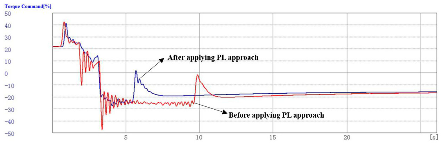
Torque command.
Conclusion
In this article, we discussed the situation of robot trajectory transfer, proposed the PL approach to solve the sharp angle between adjacent trajectories, and presented the method for calculating the related parameters of PL arc in different situations. According to the experimental results, we can draw the conclusion that the PL approach can effectively improve the speed of transfer trajectory, reduce the transfer mechanism’s vibration, and achieve high-accurate and high-speed robotic movement.
Footnotes
Academic Editor: Yong Chen
Declaration of conflicting interests
The author(s) declared no potential conflicts of interest with respect to the research, authorship, and/or publication of this article.
Funding
The author(s) disclosed receipt of the following financial support for the research, authorship, and/or publication of this article: This project is supported by Talent Fund (grant no. 2012RC021).