
Abstract
Most driving torques in serial industrial robots are used to overcome the weight of the robot. Although actuators account for a large proportion of the total mass of a robot, they have yet to become a positive factor that enables the robot to achieve gravity balance. This study presents a host–parasite structure to reconstruct the distribution of actuators and achieve gravity balance in robots. First, based on the characteristics of tree–rattan mechanisms, a method for calculating the degrees of freedom and a symbolic representation method for the distribution of branched chains are formulated for host–parasite mechanisms. Second, a configuration analysis and optimization method for host–parasite structure-based robots and a robot prototype are presented. Finally, four host–parasite mechanisms/robots (A, B, C, and D) are compared. The results are as follows. If more parasitic branched chains are added to the yz plane, the loads along axes 2 and 3 become more balanced, which significantly increases the stiffnesses of the mechanism in the y- and z-directions (Ky and Kz , respectively). If the additional branched chains are closer to the site of maximum deformation, the stiffness of the mechanism in the z-direction (Kz ) increases more significantly. Of the four mechanisms, mechanism D has the best overall performance. The joint torques of mechanism D along axes 2 and 3 are lower than those of mechanism A by 99.78% and 99.18%, respectively. In addition, Kx , Ky , and Kz of mechanism D are 100.56%, 336.19%, and 385.02% of those of mechanism A, respectively. Moreover, the first-order natural frequency of mechanism D is 135.94% of that of mechanism A. Host–parasitic structure is conducive to improving the performance of industrial robots.
Introduction
Serial robots—robots consisting mainly of serial mechanisms—have a wide range of industrial applications, such as handling, painting, welding, and assembly. 1 In a serial robot, an arm actuated by a joint acts like a cantilever beam in which the arm’s center of gravity is not aligned with the axis of the joint. Moreover, most of the joint actuation force is consumed in counteracting the moment resulting from the eccentric weight of the electric motors, gearboxes, and arms. Gravity balancing is critical for resolving such problems with robots. 2 The major methods for gravity balancing serial and parallel robots use springs, balancing mechanisms, and counterweights. 3 Liu et al. 4 used counterweights and springs in the static balancing of a parallel mechanism with six degrees of freedom (DOFs). Zhang and Wei 5 used a dynamic-balancing mechanism for parallel manipulators. Baradat et al. 6 realized the gravity balance of a Stewart platform and a Delta robot using a scissor mechanism. Yuan et al. 7 proposed a 6UPS-3UPS/UPU-R (universal-prismatic-spherical joints/universal-prismatic-universal-revolute joints) parallel mechanism and realized the gravity balance of a load through inner-layer balancing of the parallel mechanism. Zhao et al. 8 realized the gravity balance of parallel robots in the entire working envelope by designing an inner-layer-balancing mechanism with a constant Jacobian matrix. Newman and Hogan 9 realized the gravity balance of two-DOF serial robots using a parallelogram-based counterweight. In an attempt to gravity balance Scara-like robots using counterweights or springs, Bruzzone and Bozzini 10 found that the counterweight method was more efficient for low-speed motion, whereas the spring method was preferable for high-speed motion. Agrawal and Fattah 11 proposed a theory for gravity balancing of spatial serial robots using springs and auxiliary parallelograms. Gupta et al. 12 optimized the distribution of masses to reduce the driving torques and forces at the joints of a serial robot. Lee et al. 13 used a combination of a cam mechanism and a compression spring to compensate for the gravity torque of the target structure to improve energy efficiency. Feng et al. 14 proposed a new balancing mechanism for industrial robots based on elastic actuators in series. Richiedei and Trevisani 15 studied the relation between spring design and electric energy consumption in a spring balance system. Kim et al. 16 proposed a gravity compensator that can adjust the compensation torque in the roll direction using a reduction gearbox and wire cable.
The structural synthesis of multi-loop mechanisms is fundamental to the gravity balancing of robots. Huang and Zheng 17 divided a multi-loop mechanism into independent groups (loops of branched chains) according to the closing sequence of the groups. On this basis, they investigated the overconstraint of the sequential groups using screw theory and calculated the DOF of the entire multi-loop coupled mechanism based on the overconstraint. Liu et al. 18 calculated the DOF of multi-loop mechanisms by dividing them into equivalent parallel mechanisms. Li et al. 19 analyzed multi-loop mechanisms by combining biological and screw theories. Zhang et al. 20 proposed a new method for synthesizing multi-loop mechanisms based on virtual-loop theory and the Assur group. Zhang et al. 21 transformed the synthesis of multi-loop mechanisms into that of corresponding serial and parallel mechanisms according to typological split and DOF split principles. Hu et al. 22 analyzed multi-loop mechanisms by combining typology with screw theory. Xun et al. 23 proposed a novel rhombohedral three-DOF multi-loop mechanism. Ding et al. 24 proposed a general method for the structural synthesis of two-layer two-loop mechanisms. Wang et al. 25 carried out a kinematic analysis of the 2UPR-2RPU parallel mechanism, which is also a multi-loop mechanism. Chen and Sun 26 built a dynamic model of a multi-ring mechanism with multispherical joint clearances.
In summary, research progress has been made in (1) the gravity balancing of robots and (2) multi-loop mechanisms. However, the gravity balancing of serial robots with two or more DOFs remains a challenge, the theoretical understanding of multi-loop mechanisms remains limited, and there has been insufficient research into the structural optimization of multi-loop mechanisms. In the present study, based on an analysis of tree–rattan mechanisms, a numerical model is established for calculating the DOF of host–parasite (H-P) mechanisms and a method is proposed for their symbolic representation. Then, the structural characteristics of multi-loop mechanisms are analyzed by considering them as H-P mechanisms, and this method is used to optimize the structure of palletizing robots with the aim of gravity balancing their main joints. In particular, the method can be used to improve the energy efficiency and usability of industrial robots.
Analysis of the DOF of a tree–rattan mechanism
Passive DOFs
The DOF of spatial mechanisms can be expressed generally as follows 17

where n is the number of links, g is the number of motion joints, fj is the DOF of the jth motion joint, and μ is the number of overconstraints of the mechanism and is given by

where λ is the number of general constraints and ν is the number of redundant constraints (virtual constraints).
When the output link is a widely known and generally recognized output motion platform, the DOF of the output link of a mechanism is also referred to as its nominal DOF (FH ). 17 For a mechanism with a passive DOF (FP ) that does not affect the DOF of the output link (such as the roller cam mechanism shown in Figure 1), the nominal DOF can be expressed as follows

Equation (3) can be rewritten as follows 27


Roller cam mechanism.
Typology of branched chains of a multi-loop mechanism
A multi-loop mechanism is a type of closed-loop mechanism. Figure 2 shows four different multi-loop mechanisms, where Ci denotes loops that are closed in sequence. A serial kinematic mechanism (SKM) consists of several serially connected self-closed loops. A parallel kinematic mechanism (PKM) consists of several parallel-connected loops that are closed to the frame synchronously. A multi-subloop kinematic mechanism (LKM) consists of several loops that are stacked and closed in sequence, and a multichain kinematic mechanism (CKM) consists of several chains that are stacked and closed in sequence. Many more multi-loop mechanisms can be constructed by combining these four types of mechanism as branched chains in different ways.

Four different types of mechanism. (a) SKM, (b) PKM, (c) LKM, and (d) CKM.
An SKM is a special multi-loop mechanism that has closed loops. The loops of a serial mechanism are self-closed. That is, a motion joint and link together form a closed loop. For a self-closed loop of a serial mechanism, a zero-DOF two-arm branched-chain can be connected in parallel to each end of the link to form a triangular-loop serial mechanism, but without adding the DOF of the original mechanism, as shown in Figure 3. The triangular-loop serial mechanism has the following parametric values: n 1 = 10, g 1 = 12, v 1 = 0, and λ 1 = 3. Substituting these values into Eqs. (11) and (2), its DOF can be calculated as follows: μ 1 = 0 − 3 × (10 − 12 − 1) = 9 so that F 1 = 6 × (10 − 12 − 1) + 12 + 9 = 3. The original serial mechanism has the following parametric values: n 2 = 4, g 2 = 3, v 2 = 0, and λ 2 = 3. Similarly, substituting these values into Eqs. (1) and (2), its DOF can be calculated as follows: μ 2 = 0 − 3 × (4 − 3 − 1) = 0 giving F 2 = 6 × (4 − 3 − 1) + 3 + 0 = 3. Clearly, the original serial mechanism and the triangular-loop mechanism have the same DOF (F 1 = F 2) or the two are equivalent in terms of DOF. Moreover, the triangular-loop serial mechanism also has self-closed loops and is equivalent to the original serial mechanism in terms of this characteristic.

Loop self-closing of serial mechanisms. (a) Serial mechanism, (b) triangular-loop serial mechanism, and (c) loop self-closing mechanism.
Tree–rattan mechanism
Parasitism exists widely in fauna and flora. 28,29 A parasitic relationship can be considered as a mechanism in which the host is the output link and the parasite has a passive DOF. Thus, the DOF of a mechanism can be analyzed by considering it as a tree–rattan parasitic relationship or as a tree–rattan mechanism. The tree mechanism can be referred to as the host mechanism, and the rattan mechanism can be referred to as the parasitic mechanism, as shown in Figure 4. The tree–rattan mechanism is a multi-loop mechanism with passive DOF.
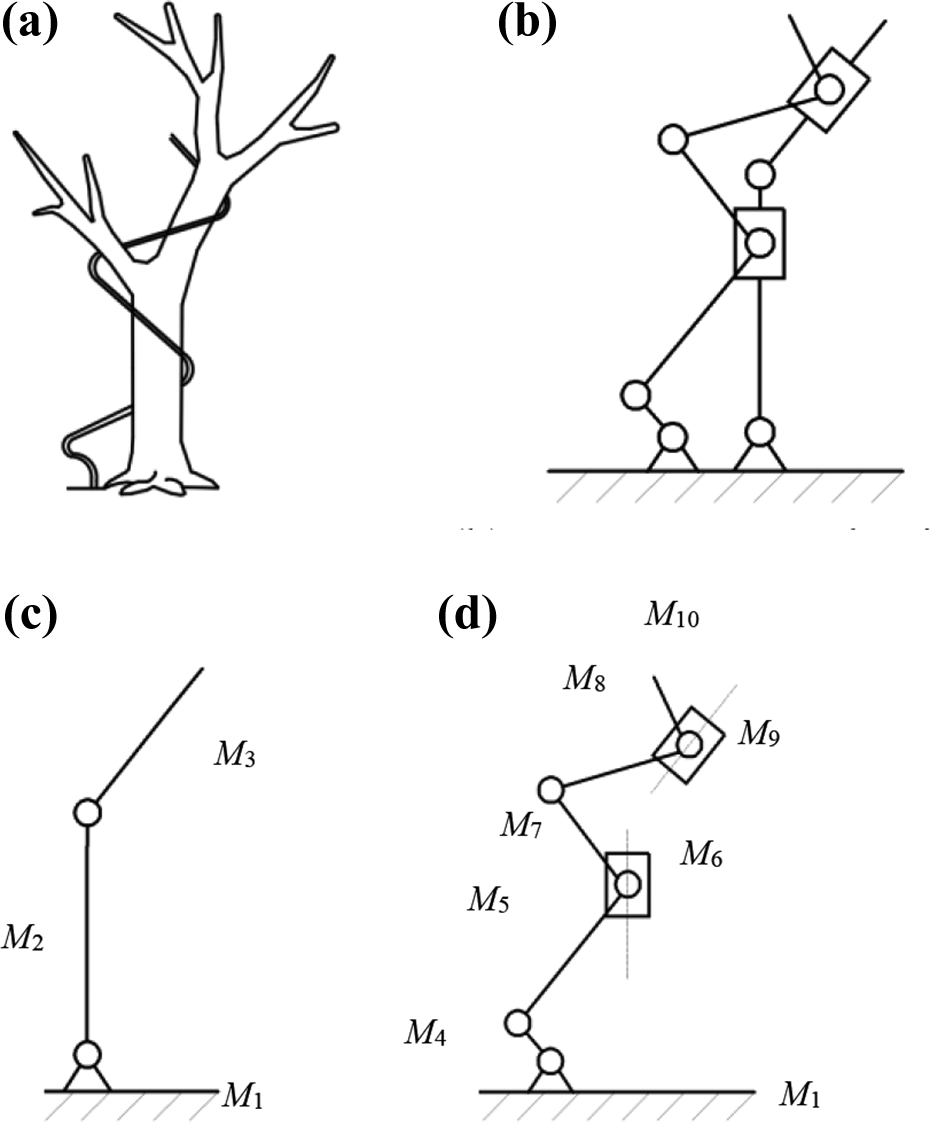
Tree and rattan mechanisms. (a) Tree–rattan parasitic relationship, (b) tree–rattan mechanism, (c) tree mechanism, and (d) rattan mechanism.
Clearly, a tree–rattan mechanism has two branched chains, namely a tree mechanism that is an SKM and a rattan mechanism that is a CKM-SKM hybrid. Tree and rattan mechanisms have overconstraints (μ). For the redundant constraints, v = 0 and for the general constraints, λ = 3 (planar constraints only). A tree–rattan mechanism has the following parametric values: n = 10, g = 11, v = 0, and λ = 3. Substituting these values into Eqs. (1) and (2), its DOF can be calculated as follows: μ = 0 − 3 × (10 − 11 − 1) = 6 giving F 3 = 6 × (10 − 11 − 1) + 11 + 6 = 5.
A tree mechanism has the following parametric values: n = 3, g = 2, v = 0, and λ = 3. Similarly, substituting these values into Eqs. (1) and (2), its DOF can be calculated as follows: μ = 0 − 3 × (3 − 2 − 1) = 0, so that F 1 = 6 × (3 − 2 − 1) + 2 + 0 = 5.
A rattan mechanism consists of two serially connected branched chains, namely a CKM and an SKM. Because the loop self-closing of serially connected branched chains does not produce an overconstraint, a rattan mechanism can be considered as a single unit in a DOF analysis. Note that in calculating the DOF of a tree mechanism using Eq. (1), the ground must be considered as a link. Similarly, because the DOF of a rattan mechanism depends on the host tree, the entire tree mechanism must be considered as a link of the rattan mechanism. Thus, in calculating the DOF of a rattan mechanism, Eqs. (1) and (2) must be revised as follows


A rattan mechanism has the following parametric values: n = 7, g = 9, v = 0, and λ = 3. Substituting these values into Eqs. (5) and (6), its DOF can be calculated as follows: μ = 0 − 3 × (7 − 9) = 6 and F 2 = 6 × (7 − 9) + 9 + 6 = 3. Clearly, F 3 = F 1 + F 2 = 2 + 3 = 5, thereby validating Eqs. (5) and (6).
In terms of the relation between the overall DOF and the DOF of the branched chains, a tree–rattan mechanism can be expressed as

where F
5
is the tree–rattan mechanism and has five DOFs,
Structural analysis of the H-P mechanism
H-P mechanism
In biology, parasitism is a symbiotic relationship between two species. One species (the parasite) lives in or on another species (the host), preying on it for nutrition and causing it some harm. 30 A tree and a rattan climbing the tree form a biological parasitic relationship, and this parasitism has implications in the theory of mechanisms. The rattan mechanism is parasitic on the tree mechanism through motion joints and benefits from the parasitic relationship. The rattan mechanism has a passive DOF and a parasitic medium, whereas the tree mechanism is constrained by the singularity of the rattan mechanism. A tree–rattan mechanism can also be referred to as an H-P mechanism. The H-P mechanism is a multi-loop mechanism with passive DOF.
A host mechanism has a dependent DOF, which can be calculated using


whereas a parasitic mechanism is one that relies on a host mechanism to form its own DOF. A parasitic mechanism can serve as a host for another parasitic mechanism. The DOF of a parasitic mechanism can be calculated using


where 1 in np + 1 indicates that the host is considered as a link of the parasitic mechanism. Note that this consideration is critical to the correct calculation of the DOF of the parasitic mechanism.
A mechanism formed by combining host and parasitic mechanisms is a hybrid mechanism and is referred to as an H-P mechanism. The overall DOF of an H-P mechanism can be expressed as follows

Thus, Eqs. (8)–(12) constitute a numerical model for calculating the DOF of H-P mechanisms. As shown above, the branched chains of mechanisms can be classified into four types, namely SKM, PKM, LKM, and CKM. An H-P mechanism formed by a combination of these four different mechanisms can be expressed as follows

where FZ
is the mechanism with an overall DOF of Z and
Characteristics of different parasitism modes
The basic parasitism modes include parasitism on a joint, on a link, and on both a joint and a link, as shown in Figure 5. Parasitic branched chains of mechanisms can be formed by combining these three parasitism modes. According to the relationship between parasitic branched chains and that between parasitic and host branched chains, the following modes of the parasitism of branched chains can be identified in H-P mechanisms: climbing, parallel, serial, stacking, splitting, and symbiotic parasitism. Table 1 compares the different parasitism modes.

Basic parasitism modes. (a) Host mechanism, (b) parasitism on a motion joint, (c) parasitism on a link, and (d) parasitism on both a motion joint and a link.
Parasitism modes.

DOF: degree of freedom; CKM: multichain kinematic mechanism; LKM: multi-subloop kinematic mechanism; SKM: serial kinematic mechanism; PKM: parallel kinematic mechanism.
Serial parasitism, also referred to as staged serial parasitism, is the staged parasitism of several parasitic branched chains on the host mechanism or on previous-level parasitic branched chains, as shown in Figure 6(a). Parallel parasitism is the parasitic parallel connection of several branched chains to a host mechanism or to previous-level parasitic branched chains, as shown in Figure 6(b). Splitting parasitism is the parasitic serial connection of several branched chains to the host mechanism or to previous-level parasitic branched chains through only one motion joint, so that it has the shape of a split in a tree branch, as shown in Figure 6(c). A two-foot or two-arm mechanism is splitting parasitism. In climbing parasitism, the host mechanism has a single-loop and the parasitic branched-chain has the same working envelope as the host mechanism, as shown in Figure 6(d). A tree–rattan mechanism is climbing parasitism, but the host mechanism is serial. In symbiotic parasitism, the links and joints of the parasitic mechanism are symbiotic with those of the host mechanism, as shown in Figure 6(e). Symbiotic parasitism enables the parasitic mechanism to have DOFs but without additional links and joints for the H-P mechanism. In zero-DOF parasitism, a parasitic mechanism with a passive DOF of zero enables the output link to have a parasitism mode, as shown in Figure 6(f). In stacking parasitism, several parasitic branched chains are stacked, as shown in Figure 6(g).

Different parasitism modes in H-P mechanisms. (a) Staged serial parasitism, (b) parallel parasitism, (c) splitting parasitism, (d) climbing parasitism, (e) symbiotic parasitism, (f) zero-DOF parasitism, and (g) stacking parasitism.
Optimization and case analyses
Palletizing robots: Problems and optimization objective
The main functions of a palletizing robot are gripping, transporting, and stacking objects. A palletizing robot may have a serial or semiserial structure, as shown in Figure 7. A six-DOF serial robot has six actuators (D 1–D 6), while a four-DOF semiserial robot has four actuators (D 1–D 4). When gripping, placing, or waiting, a palletizing robot must hover for different durations. Because of the constraints of the structural design, the robot has an eccentric center of mass. Thus, the actuators must output torque even when the robot hovers, and the control system must be robust enough to ensure that the robot can hover stably. Moreover, the electric motors and gearboxes account for 40–60% of the total mass of the robot. Thus, the robot has low mechanical efficiency and positioning accuracy and is prone to residual vibrations, all of which increase the difficulty of system control.

Schematics of (a) serial and (b) semiserial palletizing robots.
Thus, the following optimization objectives were defined for palletizing robots: (1) the robot must be able to maintain the static balance of its main joints, (2) the robot must be able to maintain the center of mass of its moving links constant in any pose at any position in its working envelope, and (3) the robot must require only a minimal counterweight for gravity balance.
Structural optimization steps
The structural optimization of a robot is gradually achieved by comparing the advantages and disadvantages of the parasitic branched chains in various optimized schemes. The symbolic representation method (Eq. (13)) for mechanisms aims to establish corresponding relationships between sub-DOFs and specific parasitic branched-chain types, while ensuring that the total number of DOFs remains unchanged in the various optimized schemes. The structure of an H-P mechanism can be optimized through the steps listed in Figure 8.
Step 1: Define the objective of the optimization: The problems with the target mechanism are analyzed and the objective of the optimization and the relevant constraints are defined.
Step 2: Analyze the DOF and the branched-chain combination of the target mechanism and identify the root causes of the problems.
Step 3: Ensure that there is no change in the total number of DOFs. This is the main constraint in structural optimization when using a symbolic representation method. Let FZ
be a mechanism where Z is the total number of DOFs. After decomposing the DOFs of FZ
,
Step 4: Reorganize the order of design schemes: to save a lot of optimization calculation time, optimization is performed in a progressive manner. The multiple configuration schemes obtained by type synthesis are sorted according to the number of parasitic branches. For example, first, the host mechanism without parasitic branch chain, then the configuration with only one parasitic branch chain, and then the configuration with multiple branches.
Step 5: Select a parasitism mode: The design options output from step 3 are analyzed, and a parasitism mode is selected based on the optimization objective and the characteristics of the available parasitism modes (Table 1).
Step 6: Assess whether the constraints for the optimization objective have been met. If not, go back to step 4 and look for other optimized schemes.
Step 7: Select an optimization option, undertake the dimensional design of a prototype, and fabricate and validate the prototype.
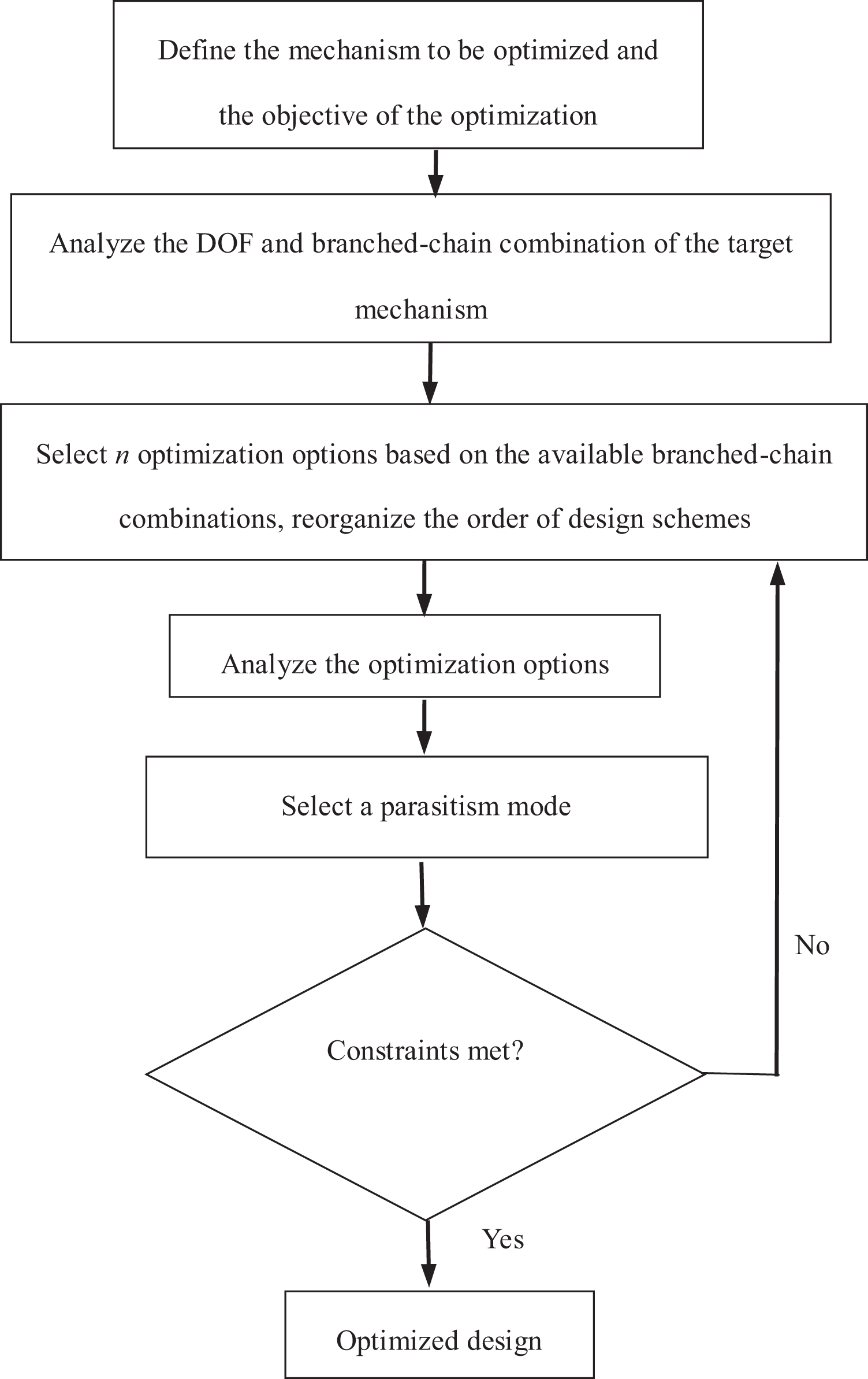
Flowchart for the structural optimization of H-P mechanisms. H-P: host–parasite.
Structural analysis
The following expression can be derived from Eq. (13) to represent a six-DOF serial robot

In a serial robot, an arm actuated by a joint acts like a cantilever beam, with the arm’s center of gravity not aligned with the axis of the joint. Moreover, most of the joint actuation force is consumed in counteracting the moment resulting from the eccentric gravity of the electric motors, gearboxes, and arms.
Similarly, the following expression can be derived from Eq. (13) to represent a four-DOF semiserial robot

A semiserial robot has the characteristics of an H-P mechanism. The branched-chain
Structural optimization
Breaking down the DOF
1) A semiserial robot can perform most palletizing and handling operations but has a lower eccentric load than a serial robot. Thus, a semiserial robot was selected for further optimization by breaking down the DOF of the host mechanism. Thus, the following expression can be derived from Eq. (13)

Changing the cantilever arms to balanced long branched chains
2) Both LKMs and CKMs can serve as long branched chains, but a CKM is a better option for a passive DOF of the far-end output link. Thus,


The static balance of the robot structure was optimized. The four DOFs correspond to the four main joints on axes 1–4, namely G 1–G 4, as shown in Figures 8 and 9. G 1 of axis 1 of the base and G 4 of axis 4 of the output link are rotations in the vertical direction. Because the load on axis 1 was markedly larger than that on axis 4, priority was given to balancing the load on axis 1 by aligning the overall center of mass of the robot with axis 1. G 2 of axis 2 and G 3 of axis 3 are rotations in the vertical plane and thus required gravity balancing. For gravity balancing of G 2 of axis 2, because the eccentric load was on the left side of the joint, all the branched chains were extended to the right side of joint G 2 and all the actuators of the branched chains were installed on the right side of the joint. In other words, leverage was used, with the joint serving as the fulcrum of the lever. Similarly, for the gravity balancing of G 3 of axis 3, all the actuators were installed on the right side of the joint.

Schematic of the H-P structure of a palletizing robot. H-P: host–parasite.
Selecting an appropriate parasitism mode
3) Four optimization options (V 1–V 4) were analyzed. Climbing parasitism was adopted for long branched chains using CKMs. Because there were no strict requirements for structural compactness, the five branched chains were configured through stacking parasitism.
The major differences between the four optimization options are in branched chains PS 1 and PS 2. For branched-chain PS 1, to utilize fully the large weight of axis 1, its actuator was moved near to axis 2. Because of the large movement required, LKM was not feasible. Thus, CKM was adopted and incorporated through climbing parasitism. For branched-chain PS 2, the actuator was also moved near to axis 2 but only by a small distance. Both LKM and CKM were feasible options for PS 2, but LKM was simpler. Table 2 compares the parasitism modes and the advantages and disadvantages of the four optimization options. The final option selected was V 3.
Parasitism modes and advantages and disadvantages of the optimization options.
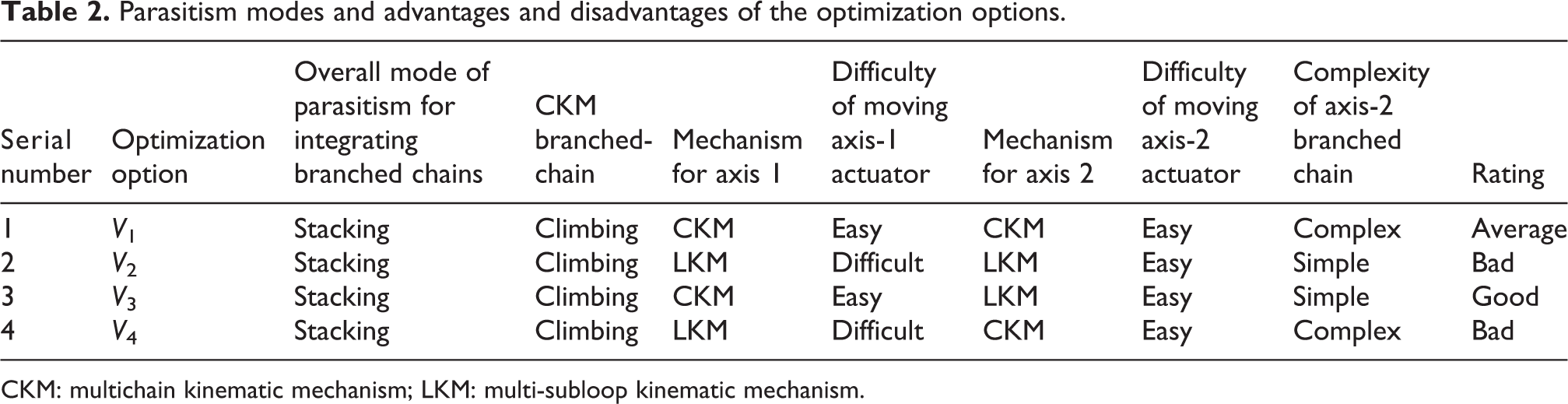
CKM: multichain kinematic mechanism; LKM: multi-subloop kinematic mechanism.
To further move the axis-1 actuator (which has already been moved to near axis 2) to the balanced side of axis 2, a zero-DOF branched-chain, LKM0, was added to branched-chain PS 1. Figure 9 shows the final design of the H-P structure of the palletizing robot. Branched-chain LKM0 is highlighted in green. The optimized structure can then be expressed as follows
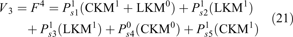
Table 3 presents the calculation of the DOF of the branched chains of the palletizing robot. The overall DOF of the optimized robot was F = 1 + 0 + 1 + 1 + 0 + 1 = 4.
Calculation of DOF of branched chains.

DOF: degree of freedom; CKM: multichain kinematic mechanism; LKM: multi-subloop kinematic mechanism.
Selecting an optimization option and fabricating prototypes
4) Based on the optimized structural design, a dimensional design was completed and a prototype H-P palletizing robot was fabricated, as shown in Figure 10. The final design of the robot had four main joints, namely G 1–G 4, and four actuators, namely D 1–D 4. A patent for the invention has been filed.

Prototype of H-P palletizing robot. H-P: host–parasite.
Analyzing operating performance
5) In the new design of the palletizing robot, all the electric motors and gearboxes as well as a small fraction of the counterweight were concentrated on the right side of G 2. None of the servomotors had a brake. The payload (10 kg) held by the robot gripper can be moved manually to any position in the working envelope and can hover for a long time without the actuators outputting torque. Because the actuators do not need to output torque when the new robot hovers at any position in the working envelope, the mechanical efficiency has also improved (by different degrees under different operating conditions). Table 4 compares the operating performance of the serial, semiserial, and H-P palletizing robots.
Operating performance of palletizing robots with different structural designs.

H-P: host–parasitel SKM: serial kinematic mechanism; CKM: multichain kinematic mechanism; LKM: multi-subloop kinematic mechanism.
Comparative analysis of H-P structures of robots
Four configurations in the formation of a new H-P mechanism
To facilitate a unified comparative analysis, four mechanisms, A, B, C, and D, were designed using the process for creating a robot prototype. Each of the four mechanisms is set to the attitude in which the manipulator extends the furthest working distance, as shown in Figure 11. Each mechanism has four DOFs (achieved jointly by axes 1, 2, 3, and 4), corresponding to the main joints G 1, G 2, G 3, and G 4 as well as actuators D 1, D 2, D 3, and D 4, respectively.

H-P mechanisms/robots with various configurations. (a) Mechanism A, (b) mechanism B, (c) mechanism C, and (d) mechanism D. H-P: host–parasite.
Mechanism A is a serial mechanism with no parasitic branched chains and can serve as a host mechanism, as shown in Figure 11(a). Mechanism B is formed by adding a balancing parasitic branched-chain and a parasitic branched-chain along axis 3 to mechanism A as well as moving actuator D 3 of mechanism A at joint G 3 to the right of joint G 2, as shown in Figure 11(b). Mechanism C is formed by moving actuator D 1 of mechanism B at joint G 1 to the right of joint G 2 via the parasitic branched-chain along axis 1 as well as moving actuator D 2 of mechanism B at joint G 2 to the right of joint G 2 via the parasitic branched-chain along axis 2, as shown in Figure 11(c). Mechanism D is formed by moving actuator D 4 of mechanism C at joint G 4 to the right of joint G 2 via the parasitic branched-chain along axis 4, as shown in Figure 11(d).
The position of the center of mass and joint torque
Figure 12 shows a Cartesian coordinate system xyz for the robots. The y- and x-axes coincide with axes 1 and 2, respectively. The point of intersection of axis 1 and the ground is the origin of the coordinate system, O. The mass of each component of each robot is simplified as a mass point mi
. Let


Deformation of various robots in the x-direction under the external load F e1. (a) Mechanism A, (b) mechanism B, (c) mechanism C, and (d) mechanism D.
Let M 0 be the mass of the system of mass points of the base. Let MG 1, MG 2, MG 3, and MG 4 be the masses of the systems of mass points that rotate relative to axes 1, 2, 3, and 4, respectively. The judgment method is as follows: for example, consolidate axes 2, 3, and 4, rotate axis 1, and observe which robot parts rotate around axis 1.Then

The position of the center of mass (

The components of the above equation are as follows

The positions of the centers of mass of each of the systems of mass points with masses MG 1, MG 2, MG 3, and MG 4, respectively, are as follows


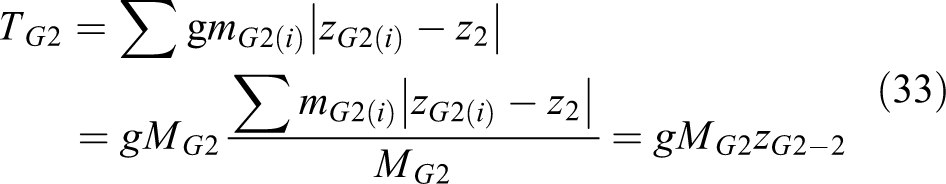
Let z
2 and z
3 be the positions of axes 2 and 3 in the z-direction, respectively. To facilitate the comparison of the changes in the position of the center of mass in the z-direction relative to axes 2 and 3,


To analyze the relationship between the mass of the actuators and the mass of all the movable robot components (
Here, only the gravitational effect g is taken into consideration. Let

In this study, the mass and position of the center of mass of each component of each robot were determined based on its three-dimensional (3D) model. In addition, the following parameters were also obtained: z
2 = 0.00000 m, z
3 = 0.72582 m, and
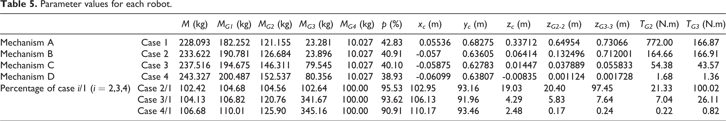
Parameter values for each robot.
To verify the accuracy of the centroid position model, the starting torque of the 2-axis and 3-axis of the mechanism D measured by the torque sensor is 6.83 Nm and 4.89 Nm, respectively, and the model calculation results are 1.68 Nm and 1.36 Nm. Due to the friction force of the joint bearing and the weight of the torque sensor, the experimental result is larger than the model calculation result. The experimental results are of the same order and close to the model calculation results, so the accuracy of the robot centroid position model is verified.
Here, the data for mechanism A are used as the reference. The parasitic branched chains (excluding the actuators) account for a relatively small proportion of the total mass. Compared to mechanism A, the most significant increase in M and MG1 was found with mechanism D. Specifically, M and MG1 of mechanism D are 6.68% and 10.01% higher than those of mechanism A, respectively. The changes to MG2 and MG3 were primarily caused by the relocation of the actuators and the changes in the parasitic branched chains. MG4 is the workload at the end of the robot. The values of P for the four mechanisms are 42.83%, 40.91%, 40.10%, and 38.93%, respectively. This suggests that the actuators account for a very large proportion of the total mass of the movable robot components.
Mechanism B was formed only by moving actuator D 3 of mechanism A from joint G 3 to near joint G 2. As actuator D 3 plays no role in balancing joint G 3, there are no notable differences in zG 2–3 and TG 3 between mechanisms A and B. However, actuator D 3 balances joint G 2. This results in a decrease of zC and zG 2–2 to 19.03% and 20.40% of the respective reference values. This suggests that compared to mechanism A, the systems of mass points of mechanism B with masses M and MG2 are significantly closer to axes 1 and 2 in the z-direction. This also leads to a decrease in TG 2 to 21.33% of the reference value.
Compared to mechanism A, actuator D 3 of mechanism C is located at an outer position and plays a role in balancing both joints G 2 and G 3. In addition, compared to mechanism A, actuators D 1 and D 2 of mechanism C are located to the right of joint G 2 and play a role in balancing joint G 2. This results in a decrease in zC , zG 2–2, and zG 3–3 to 4.30%, 5.83%, and 7.64% of the respective reference values. This suggests that compared to mechanism A, the systems of mass points with masses M, MG 2, and MG 3 of mechanism C are significantly closer to axes 1, 2, and 3 in the z-direction. This also results in a decrease in TG 2 and TG 3 to 7.04% and 26.11% of the respective reference values.
Compared to mechanism A, actuator D 4 of mechanism D is also to the right of joint G 2 and balances both joints G 2 and G 3. This results in a decrease in zC , zG 2–2, and zG 3–3 to 2.48%, 0.17%, and 0.236% of the respective reference values. This suggests that compared to mechanism C, the systems of mass points with masses M, MG 2, and MG 3 of mechanism D are even closer to axes 1, 2, and 3 in the z-direction. This also results in a decrease in TG 2 and TG 3 to 0.22% and 0.82% of the respective reference values. Evidently, gravity balance has basically been achieved in mechanism D along axes 2 and 3.
Comparative analysis of stiffness and mode
In this section, the relationship between translational deformation and external forces (excluding moments) is examined for these four robots. The external load Fe at the end of each robot can be represented by the following matrix

The following equation shows the relationship between Fe
, the stiffness K, and the overall deformation

where

The 3D robot models were imported into Ansys Workbench for a stiffness and modal analysis. The following boundary conditions were set for each robot. The base was fixed to the ground. A unidirectional external load was applied to the end surface of the flange at the end of the robot. Gravity was taken into account for all components. Meshes were generated for mechanisms A, B, C, and D using the automatic mesh generation technique, which produced a combination of tetrahedrons and hexahedrons. In total, 719,487, 781,413, 1,229,640, and 1,314,024 mesh cells were generated for mechanisms A, B, C, and D, respectively. No-separation contact conditions were applied to the connecting links that move relative to one another at the joints, whereas bonded contact conditions were applied to all other components. 31 The parameters of each robot component were set based on the material used in practice to produce it.
Let Kx , Ky , and Kz be the K values for each robot in the x-, y-, and z-directions, respectively. An external load was applied to the center of rotation of the end surface of the flange along the negative x-direction (Figure 12)

Figure 12 shows the deformation in the x-direction.
An external load along the negative y-direction was applied to the end surface of the flange

Figure 13 shows the deformation in the y-direction.

Deformation of various robots in the y-direction under the external load F e2. (a) Mechanism A, (b) mechanism B, (c) mechanism C, and (d) mechanism D.
An external load along the negative z-direction was applied to the end surface of the flange

Figure 14 shows the deformation in the z-direction.

Deformation of various robots in the z-direction under the external load F e3. (a) Mechanism A, (b) mechanism B, (c) mechanism C, and (d) mechanism D.
As robot links are made mainly of aluminum alloys and the furthest working distance is 1.638 m, the K values of mechanisms A, B, C, and D are relatively low. Table 6 summarizes the maximum deformation K and the natural frequencies of each of the four mechanisms.
Maximum deformation K and the natural frequencies of each robot.

To verify the accuracy of the robot stiffness model based on the finite element method, an experimental measurement system for the deformation of the mechanism D is established, as shown in Figure. 15. The robot and the lifting jack are fixed to the ground and the wall, respectively, add a force of −100 N in the X, Y, and Z directions of the robot end through the lifting jack, measure the force of the lifting jack loading through the force sensor, and then use a micrometer to measure the deformation of the mechanism D. The stiffness is obtained by conversion from Eq. (36). The experimental results are Kx1 = 33 N/mm, Ky1 = 89 N/mm, and Kz1 = 870 N/mm, and the finite element calculation results are Kx2 = 24 N/mm, Ky2 = 88 N/mm, and Kz2 =558 N/mm. The maximum deviation between the finite element calculation results and the experimental results is 35.58%. Because the finite element model does not consider the friction force of the joint bearing and the irregular geometry is simplified, the calculation result of the finite element model is smaller than the experimental result. The results of the finite element calculation are the same as and close to the experimental results, so the accuracy of the robot stiffness model is verified.

Experimental measurement system of the deformation of the mechanism D.
The data for mechanism A are used as the reference. The Kx values of mechanisms C and D differ relatively insignificantly from that of mechanism A. In contrast, Kx of mechanism B (119.31% of the reference value) is slightly higher than that of mechanism A. This suggests that the added parasitic branched chains exert no significant impact on Kx .
The Ky values of mechanisms B, C, and D are significantly higher than the reference value. Specifically, the Ky values of mechanisms B, C, and D are 216.13%, 276.13%, and 336.19% of the reference value, respectively. This suggests that if more parasitic branched chains are added to the yz plane, then the loads along axes 2 and 3 are more balanced and there is a significant increase in Ky .
The parasitic branched-chain added to mechanism A to form mechanism B is at the site of the maximum deformation of mechanism A. As a result, the most significant increase in Kz is found in mechanism B. Specifically, Kz of mechanism B is 490.03% of the reference value. In addition, the Kz values of mechanisms C and D are also significantly higher than the reference value (358.48% and 385.02% of the reference value, respectively). This suggests that if the branched chains added to the yz plane are closer to the site of maximum deformation, then the increase in Kz is more significant. Compared to the location where branched chains are added, the extent to which the loads along axes 2 and 3 are balanced has a secondary impact on Kz .
Next, we compared the first three orders of the natural frequencies of the mechanisms. Compared to mechanism A, mechanisms B and C each have an additional parasitic branched-chain along axis 3. As a result, the first-order natural frequencies of mechanisms B and C are 118.67% and 118.48% of the reference value, respectively. The effects of the parasitic branched chains along axes 1 and 2 are insignificant. Compared to mechanisms B and C, mechanism D has a parasitic branched-chain along axis 4. This leads to a further increase in the first-order natural frequency to 135.94% of the reference value. For the four mechanisms, as the number of parasitic branched chains increases, there is a decrease in the second-order natural frequency but an increase, to varying degrees, in the third-order natural frequency.
Conclusions
Serial robot is a widely used industrial robot. The serial robot has the advantage of large working space but also has the disadvantages of low motion accuracy, low rigidity, and low mechanical efficiency. The purpose of this study is to propose a H-P structure to reconstruct the driver distribution, achieve the gravity balance of the serial robot, and improve the performance of the robot. This study analyzed the characteristics of tree–rattan mechanisms in terms of DOFs and branched chains. We developed an H-P structure with multi-loop mechanisms and formulated a method for calculating DOFs and a symbolic representation method for branched-chain distributions of H-P mechanisms. Based on the H-P structure, the configuration of full- and semiserial palletizing robots was optimized and an innovative design was developed. In addition, new palletizing robot prototypes with a gravity-balancing function were also developed. The H-P structure renders it possible to redistribute the actuators and masses in the robots. M
4D of mechanism A accounts for 42.83% of its MG
1. Three mechanisms, B, C, and D, were formed by moving M
4D as a whole to the balance positions along axes 2 and 3 by way of parasitic branched chains. For mechanisms B, C, and D, the joint torques of mechanism D differ the most significantly from those of mechanism A. Specifically, the joint torques of mechanism D along axes 2 and 3 are 99.78% and 99.18% lower than those of mechanism A, respectively. A static balance along axes 2 and 3 was achieved in mechanism D. Adding parasitic branched chains can help improve the K of robots. If more parasitic branched chains are added to the yz plane, then the loads along axes 2 and 3 are more balanced and the increase in Ky
and Kz
of the mechanism is more significant. If the additional branched chains are closer to the site of maximum deformation, then the increase in the Kz
of the mechanism is more significant. In particular, Kx
, Ky
, and Kz
of mechanism D are 100.56%, 336.19%, and 385.02% of those of mechanism A, respectively. For the four mechanisms, as the number of parasitic branched chains increased, there was an increase, to varying degrees, in the first- and third-order natural frequencies but a decrease in the second-order natural frequency.
Footnotes
Declaration of conflicting interests
The author(s) declared no potential conflicts of interest with respect to the research, authorship, and/or publication of this article.
Funding
The author(s) disclosed receipt of the following financial support for the research, authorship, and/or publication of this article: This work was supported by the National Natural Science Foundation of China (Grant No. 51765005) and the Open Foundation of Guangxi Colleges and Universities for Key Laboratory of Robot and Welding (Grant No. JQR2015KF03).