
Abstract
The key technology of vibrating screens’ design is how to ascertain the synchronous state of vibrating systems. The occurrence of synchronization of a model, two co-rotating rotors fast excited by induction motors installed in a vibrating body, is treated in this article. The synchronization condition and stability criterion of the system are first derived by the energy balance method. The synchronization zones and stable phase difference are then estimated by the two co-rotating rotors operated in synchronous state. Moreover, the energy balance mechanism of the system is explained. The transfer of energy between the rotors by the vibrating body is presented as well. Finally, numerical studies of the dynamics are performed by Runge–Kutta method to verify the theoretical analysis. The results indicated that the synchronous state of the vibrating system is mainly determined by installation distance coefficient rl, installation angular β, symmetric coefficient δ, and electromagnetic torque Tei, but little influenced by mass ratios η and rm.
Introduction
Vibration synchronization is a ubiquitous form of motion in nature. When the vibration motion of a system is influenced by the oscillations of (an)other vibration systems, this phenomenon is considered as an adjustment of rhythms of oscillating objects due to their internal weak couplings, which is called “synchronization.” Our surroundings are full of synchronization phenomenon, for example, violinists play in unison, insects in a population emit acoustic or light pulses with a common rate, birds in a flock simultaneously flap their wings, the heart of a rapidly galloping horse contracts once per locomotory cycle, and so on. Huygens 1 described the notion of the synchronization by experiments that two pendulum clocks hanging from a suspended wooden bar. BVd Pol 2 showed that the frequency of a generator can be entrained or synchronized by a weak external signal of a slightly different frequency. J Rayleigh 3 presented an interesting phenomenon of synchronization in acoustical systems. The theoretical explanation of synchronization in mechanical oscillators, pendulum clocks, the system of rotating elements, but also some electronic and quantum generator are given by II Blekhman.4–7 And L Cveticanin 8 describes a method on balancing a flexible rotor with variable mass. A Pikovsky et al. 9 published a monograph with respect to the explanation for synchronization regime, which consider synchronization as a universal concept in non-linear sciences. Nowadays, for synchronization study, the researchers mainly focus on physical, biological, chemical, mechanical, and social systems.10–12 The most representative is mechanical synchronization of multiple coupling pendulums and rotors in vibrating systems. For synchronization of multiple coupling pendulums, M Senator 13 developed synchronization of two coupled, similarly sized and escapement-driven pendulum clocks. V Jovanovic and S Koshkin 14 studied two models of connected pendulum clocks synchronizing their oscillations, a phenomenon originally observed by Huygens with the Poincaré method. J Peña Ramirez et al. 15 further perfected the theoretical investigation of synchronization of Huygens’ coupled clock combining Poincaré method with the finite element method. P Koluda et al. 16 studied a multiple self-excited double pendula hanging from a horizontal beam with the energy balanced method and explained how the energy is transferred between the pendula via the oscillating beam. The investigation of synchronization for rotor systems is a significant precondition to invent new vibration machines, including the self-synchronous vibration feeders, self-synchronous vibration conveyors, synchronous rolling mills, and so on. Wen et al. 17 developed the average method to study synchronization of the rotors fixed in a vibrating body, meanwhile, many synchronization machines are introduced by applying this synchronization theory. L Sperling et al. 18 presented theoretical and numerical method to explore a two-plane automatic balancing device for equilibration of unbalance rigid-rotor. JM Balthazar et al.19,20 examined self-synchronization of four non-ideal exciters in non-linear vibration system via computer simulations. Djanan et al. 21 explored the synchronization condition for a system, three motors working on a plate, and the synchronous state depends on the physical characteristics of the motors and the plate. Zhao et al. 22 and Zhang et al. 23 proposed the average method of modified small parameters to investigate the synchronization of exciter systems, which immensely simplify the process of solving synchronization for the systems. Fang et al. 24 applied Zhang’s method to investigate the self-synchronization of two co-rotating rotors coupled with a pendulum rod in a far-resonant vibration system. For investigation of rotor dynamics, K Samantaray et al.25–27 considered that the non-ideal rotor and sommerfeld effect influence on the dynamics characteristics, which promotes the development of the dynamics theory of the rotors. In this article, we introduce energy balance method to study the synchronization of the rotor system. With this method, we can not only easily understand the regime of the synchronization but also accurately compute the synchronous state of the system.
This article is organized as follows. First, the dynamic model of the system is briefly described in section “The dynamic model of system.” Section “Energy balance of the vibration system” presents energy balance equation of the system in the synchronous state. Synchronization condition and stability criterion of the two rotors based on the energy balance method are derived in section “Synchronization condition and stability criterion.” In section “Numerical simulation discussions,” the synchronization zones for the system are estimated, and the theoretical approximate solutions for the stable phase difference are computed. In section “Sample validations,” computer simulations for the dynamics equations are performed with Runge–Kutta method to verify the correctness of the theoretical solutions. Finally, the results are summarized in section “Conclusion.”
The dynamic model of system
The analyzed system is shown in Figure 1. It consists of a vibrating body, two unbalanced rotors, and some elements of spring and damper. The vibrating body of mass m can vibrate in x-, y-, and ψ-directions, and its movement directions are described by coordinates x, y, and ψ, respectively. The vibrating body is connected to the refuge by four linear springs symmetrically installed with stiffness coefficient kx/2 and damping coefficient fx/2 in x-direction, with stiffness coefficient ky/2 and damping coefficient fy/2 in y-direction, with stiffness coefficient kψ and damping coefficient fψ in ψ-direction, respectively. Unbalanced rotor i (for i = 1, 2) is modeled by a point mass mi attached at the end of a massless rod of length r. The rotation angle of rotor i is denoted by φi (for i = 1, 2). Moreover, Mi represents the electromagnetic torque of the induction motors, which provide the needed energy to compensate the energy dissipation to persistently keep the rotor rotation (the model of the motor introduced in Zhao et al. 22 ). The mass center of the rigid vibrating body is point o. As illustrated in Figure 1(b), three reference frames of the system can be assigned as follows: the fixed frames oxy; the non-rotating moving frames o′x′y′, which undergoes the translation motion while remaining parallel to oxy; and the rotating frames o′x″y″, which dedicates the rotation motion around points o′. The three reference frames of the vibrating body coincide with each other in the static equilibrium state. According to Lagrange’s equations, the dynamic motion of the system can be given as follows 16


The model of the vibrating system: (a) the dynamic model of the vibrating system with two induction motors rotating in the same direction and (b) the reference frame system.
In equations (1)–(4), li is the distance between the rotating centers of the rotors and the mass center of the vibrating body, β is the angle between o″oi and x-direction, J is the moment inertia of the whole vibrating system about the mass center of the vibrating body, J0i is the moment inertia of unbalanced rotor i,
As shown in Figure 1, assuming the average phase and the phase difference of the two unbalanced rotors to be ϕ and 2α, 21 respectively, then we have

Therefore, the average mechanical angular velocity of two rotors is φ. Due to the periodical motion of this vibration system, the mechanical angular velocities of two rotors change periodically. If the least common multiple period of two motors is also supposed to be T, the average value of their average angular velocity could be considered as a constant, 21 that is

Assuming the instantaneous fluctuation coefficients of φ and
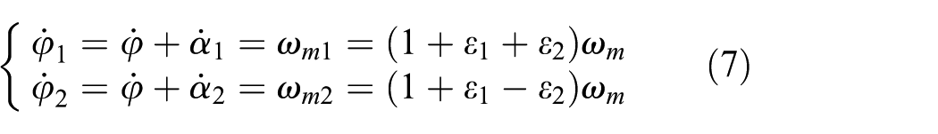
Neglecting small parameters ε1 and ε2, with average angular velocity ωm, the average phase can be approximately expressed as 21

According to equation (7), the rotation acceleration of the rotors can be expressed in the formulae

In equation (9), considering
According to equations (2)–(4), the steady response of the vibrating system, with neglecting the small parameters, can be expressed as follows

where
ξnj is the damping ratio of the springs in the j-direction (considering ξnj≤ 0.07 in this article). Differentiating the formulas in equation (10) with respect to time t,
Energy balance of the vibration system
Multiplying equation (1) by angular velocity

The first component of equation (11) indicates the inertia energy that the induction motors act on the ith rotor. Because this term related to small parameters, therefore

The rest four components of equation (11) describe the synchronous energy between the ith rotor and the vibrating body

The right-hand side of equation (11) depicts the output energy of the motors

Substituting equations (12)–(14) into equation (11), the energy balance of the ith rotor is obtained as

Multiplying equation (2) by the velocity of the vibrating body in x-direction and integrating it over the period T, the equation of the energy balance of the vibrating body is given as

The first component on the left-hand side of equation (16) represents the energy of inertia force in the x-direction during the period T. Owning to the periodic motion of vibrating body in the synchronous state, we have

The last component on the left-hand side of equation (16) stands for the energy of the potential force in the x-direction. Due to the character of the potential force, we have

Substituting equations (17) and (18) into equation (16), the energy balance of the vibrating body can be expressed as

Then multiplying equation (3) by the velocity of the vibrating body in y-direction and integrating it over the period T, the equation of the energy balance of the vibrating body is presented as

The first component on the left-hand side of equation (20) represents the energy of inertia force in the y-direction; therefore, we have

The last component on the left-hand side of equation (20) stands for the energy of the potential force in the y-direction, and so we have

Substituting equations (21) and (22) into equation (20), the energy balance of the vibrating body in y-direction can be expressed as

Then multiplying equation (4) by the velocity of the vibrating body in ψ-direction and integrating it over the period T, the equation of the energy balance of the vibrating body is written as
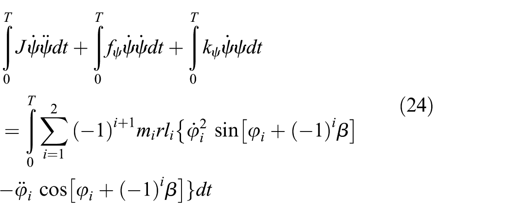
The first component on the left-hand side of equation (24) represents the energy of inertia force in ψ-direction during the period T, and so we have

The last component on the left-hand side stands for the energy of the potential force in ψ-direction, so

Substituting equations (25) and (26) into equation (24), the energy balance of the vibrating body in y-direction can be expressed as

Adding together equations (19), (23), and (27), the energy balance of the vibrating body in x-, y-, and ψ-directions is yielded as

Synchronization condition and stability criterion
Condition of synchronization
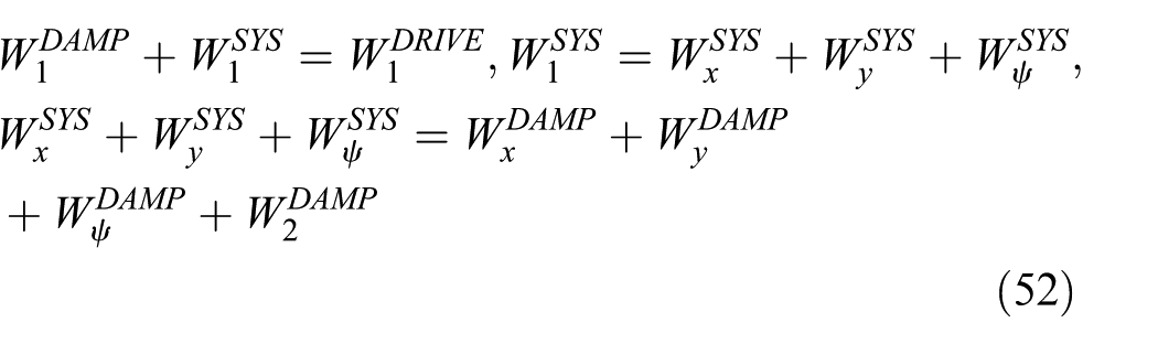
Adding equations (15)–(28), the energy balance of the whole system in following form can be expressed as
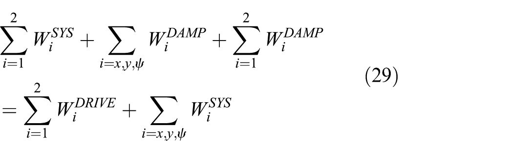
During synchronous state, the energy supplied with the motors is dissipated by all of the dampers in the vibration system, we have
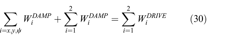
with

Substituting equation (28) into equation (30) and considering equation (31), the energy balance of the whole system during the synchronous state can be rewritten as
Equation (32) describes the energy balance of the whole system within the synchronous state in period T. According to this equation, it is known that the energy produced by the motors is balanced by synchronization energy and the dissipated energy of the motors.
In actual engineering applications, the same type motors hold the different electrical characteristic as manufacturing tolerances. Subtracting the energy balance of the two rotors according to equation (15), during the synchronous state, the difference equation of the energy of the system is given by

To ensure the implementation of the synchronous operation of the system, the system will adjust the phase difference between the rotors by itself.
In the synchronous state, the phase angle difference (φ1−φ2 = 2α) between the two rotors should be a constant and independent of the initial conditions, and instantaneous fluctuation coefficients ε1 and ε2 are equal to zero. If the parameters of the vibrating system satisfy the energy balance equation and the energy difference equation, that is, equations (32) and (33), the system can implement the synchronous operation. Substituting equations (7) and (10) into equations (32) and (33) with neglecting the small parameters, we have

Considering

Substituting

with


where
The first formula of equation (36) is the equation of torque balance of the system in the synchronous state, which serves to find the approximation value of synchronous angular velocity ωm. Moreover, the second formula of equation (36) is the balance equation of the torque difference of the system in the synchronous state, which serves to determine the approximation value of stable phase difference 2α. Therefore, the system adjusts the phase difference between the rotors to satisfy the second formula of equation (36).
Specifying TSYS as the synchronization torque of the vibration system, we obtain

Then assigning TEXC as the excessive torque of the rotors, we have

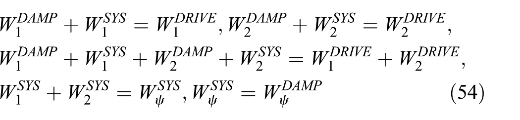
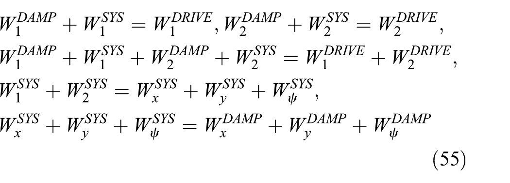
where TRES1 and TRES2 represent the residual torques of rotors 1 and 2, respectively, which can be written as

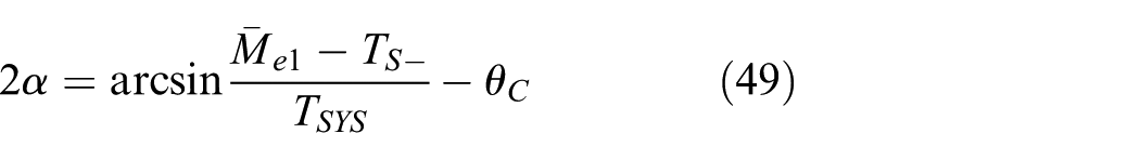
Rewriting the second formula of equation (36), we can obtain
To ensure the existence of the solution to 2α, we should have

If the excessive torque of the motors approaches to zero (i.e.
Stability criterion of synchronization
The synchronous stability criterion of system will be discussed in the following by solving a disturbance differential equation. Introducing disturbance parameters

From equation (42), it should be noted that

According to equation (36), equation (43) can be rewritten as

Actually, the damping coefficients in the two motor shafts are very small, and so

where
According to the stability theory, the coefficient of the third item of equation (45) must be positive as the first two terms are obviously greater than zero. In this case, the synchronous state of the system can be stable. As

In the weak damper system, it can be seen that
Numerical simulation discussions
In the numerical simulation discussions, the following system parameters are considered. We assume the parameters of the two motors are identical (i.e. rated power = 0.7 kW, rated voltage = 220 V, rated frequency = 50 Hz, pole pairs = 2, stator resistance = 0.56 Ω, rotor resistance = 0.54 Ω, stator inductance = 0.1 H, rotor inductance = 0.12 H, mutual inductance = 0.13 H, and the damping coefficient of shafting = 0.04 N m/(rad s)). The structural parameters of the system are as follows: m1 = 4 kg, m2 = 1–4 kg, m = 80 kg, r = 0.04 m, le = 0.3 m 0 < l1 < 2.1 m, l2≤l1 (
Synchronization zones of the system
Equation (41) has given the synchronous condition of the system, on which the zones of synchronization of the rotors can be ascertained. Substituting the above-mentioned parameters into equation (41), the synchronization zones can be depicted, as shown in Figure 2. These figures are divided into the white, black, and gray zone, respectively. If the value of the system parameters locate in the gray zone, the value of the stable phase difference belongs to the interval of
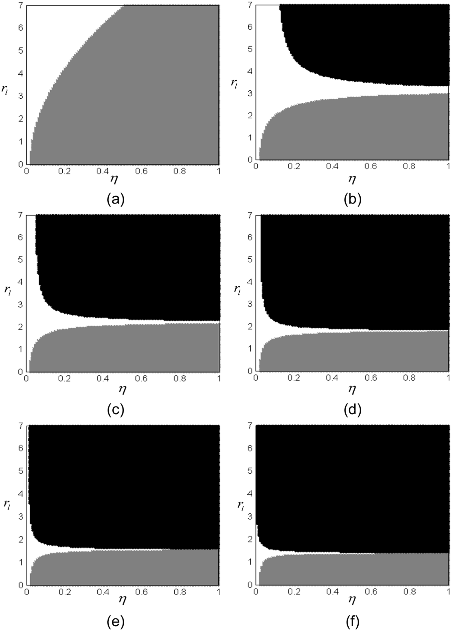
The synchronization zones for the variation of parameter δ when β = 0°: (a)

The synchronization zones for the variation of parameter β when δ= 1.0: (a)
Solutions of stable phase difference between the two rotors
In this section, the theoretical solutions of the stable phase difference will be quantitatively discussed considering the following features of the system: identical rotors symmetrically placed, non-identical rotors asymmetrically placed, non-identical rotors symmetrically placed, and turning off the power source.
From equation (40), the main parameters influencing on the stable phase difference are

We assume here that

According to equation (48), the stable phase difference between the rotors can be computed with numerical method. Figure 4 shows the approximate value of the phase difference in the power-supplying state. It can be seen that the value of parameters β, rl, and δ determine the synchronous state of the system. Especially, it is noted that the phase difference is close to 180° for β = 90°. However, for δ≠ 0, the synchronous behavior of the system will approach to the in-synchronous state with increasing the value of parameter rl and decreasing the value of parameter β. The phenomenon implies that the farther installation distance and smaller installation angular of the rotors are beneficial to the anti-phase synchronization of the system. Otherwise, the synphase synchronization will be conducted.

Approximate theoretical solutions for synchronous state in the power-supplying state. In this figure, coordinate X represents the value of the installation angular β of the rotors. Coordinate Y represents the value of the installation displacement rl of the rotors; and coordinate Z represents the value of stable phase difference 2α: (a)
Then, the synchronous state of the system will be discussed, when turning off the power source of the second motor. Therefore, parameters
According to Djanan et al.
21
and Zhao et al.,
22
when the induction motor operates with the steady velocity

where Lmi is the mutual inductance of the ith induction motor, Lsi is the stator inductance of the ith induction motor, np is the number of pole pairs of the induction motor, ωs is the angular velocity of synchronous electric, Rri is the rotor resistance of the ith induction motor, and Us0 is the amplitude of the stator voltage vector.
Substituting the given parameters of the motors into equation (50), the electromagnetic torque of the second motor can be defined. In addition, according to equation (49), the synchronous state of the system in the power-cutting state can be estimated. Figure 4 shows the stable phase difference in the power-cutting state. The phase difference in the power-cutting state is larger than the power-supplying state owing to the existence of the electromagnetic torque

Approximate theoretical solutions for the synchronous state in the power-cutting state. In this figure, coordinate X represents the value of the installation angular β of the rotors; coordinate Y represents the value of the installation displacement rl of the rotors; and coordinate Z represents the value of stable phase difference 2α: (a)
Sample validations
Further analyses have been performed by MATLAB to verify the correctness of the above theoretical solutions for synchronous state of the system, and the models of the induction motors are established with asynchronous machine SI units and three-phase programmable voltage source in MATLAB. The Runge–Kutta algorithm with adaptive step size control is used to compute the dynamics equations (1)–(4).
Simulations for rl = 2, β = 0°, δ= 1, rm = 0.02, and η = 1
Before entering into the power-cutting state, the synchronous implementation of the system must go through two operation steps. First, the two rotors connected with the induction motors are continuously supplied with the power sources; after a while, the system achieves the synchronous state, which can be called as the power-supplying stage. Second, the power source of the second motor is cut off; after a while, the system achieves another synchronous state, which can be called as the power-cutting stage.
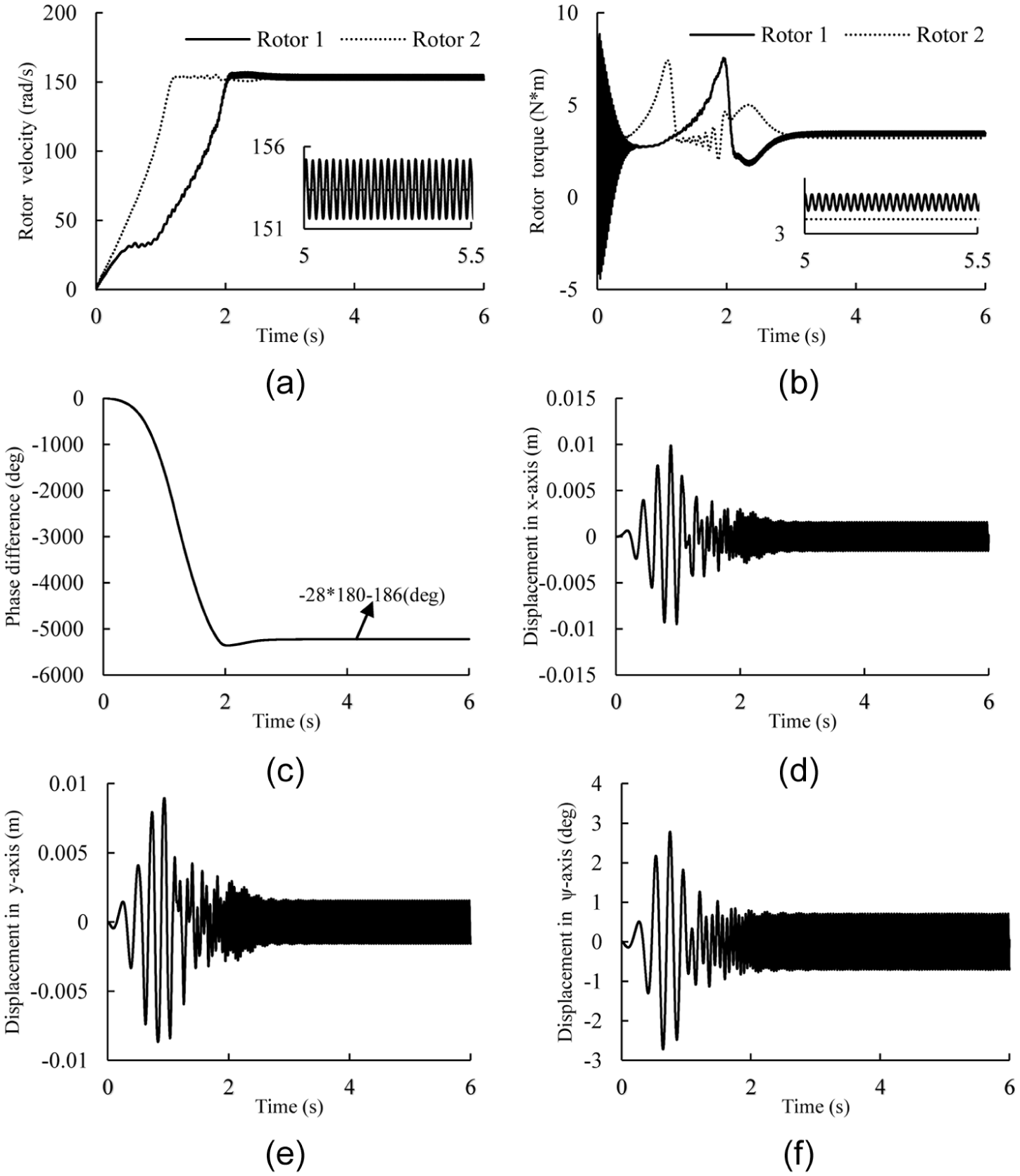
A synchronous example for the power-cutting state is performed with MATLAB. The following parameters, rl = 2, β = 0°, δ= 1, rm = 0.02, and η = 1, are considered (in this case, the value of the parameters in equations (1)–(4) are M = 80 kg, m1 =m2 = 4 kg, r = 004 m, l0 = 0.3 m, and l1 = l2 = 0.6 m). In the simulation model, the two rotors are supplied with the power source at first 2.5 s, and the power source on motor 2 is cut off at 2.5 s.
It is noted that the value of the system parameters located in the black zone in Figure 2(f); therefore, the phase difference should belong to interval

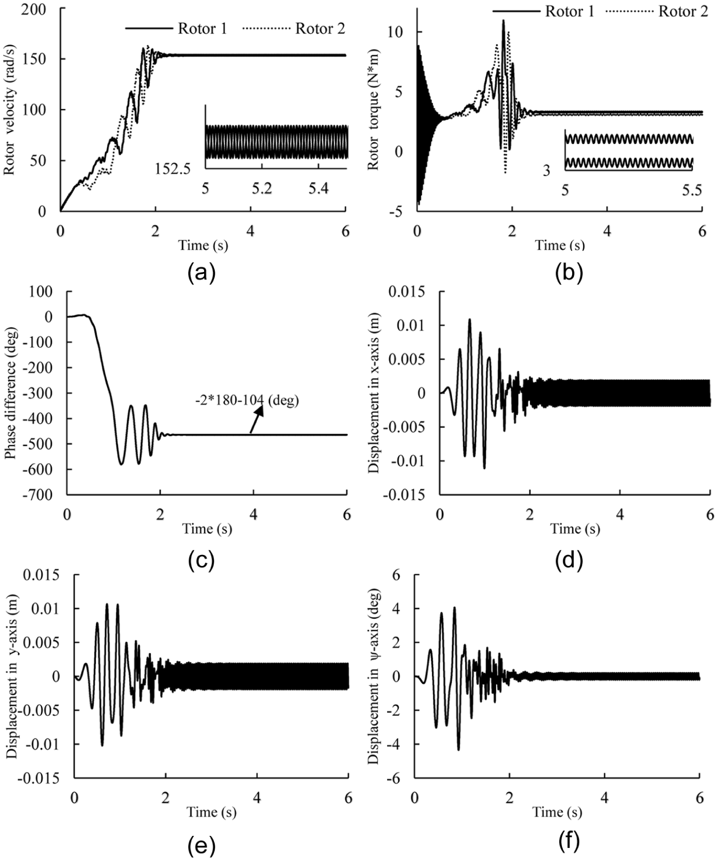
Simulation results for rl = 3, β = 45°, δ= 1, rm = 0.02, and η = 1: (a) Rotor velocity, (b) Rotor torque, (c) Phase difference, (d) Displacement in x-axis, (e) Displacement in y-axis and (f) Displacement in
When entering into the power-cutting state, the rotational velocity of the rotors is decreased to 147 rad/s. The phase difference is increased to 38° from 1.2°, which is according with theoretical computation in Figure 5(a) (i.e. the stable phase difference in Figure 5(a) is equal to 41.8°, and here the phase difference is equal to 38°). The electromagnetic torque of rotor 1 becomes zero when the power source of induction motor 2 is cut off at 2.5 s, and the electromagnetic torque of motor 2 is increased to 6.85 N m for balancing the resistances and frictions of the system. Figure 6(d)–(f) describes the responses of the system in x-, y-, and ψ-directions. In the starting stage, the displacements in x-, y-, and ψ-directions are by far larger than other stages as the exciting frequency go through the resonant region. In the power-supplying state, the steady displacements in x- and y-directions are smaller than that of the power-supplying state.
In the power-supplying state, the part energy supplied by the two induction motors is dissipated by their friction dampers (

In the synchronous state, the energy balance of the power-supplying system is depicted in Figure 7(a).

Energy balance of the vibrating system in the synchronous state: (a) The power-suppling state, (b) The power cutting state, (c) The asymmetrical installation of the non-identical rotors and (d) The symmetrical installation of the non-identical rotors.
However, the electromagnetic torque of the rotor is equal to zero in the power-cutting stage (see in Figure 6(b)). It is noted that the displacement in ψ-direction cannot be neglected. In this case, the synchronous energy (
In the synchronous state, the energy balance of the power-cutting system is depicted in Figure 7(b).
Simulations for rl = 2, β = 0°, δ= 0, rm = 0.02, and η = 0.25
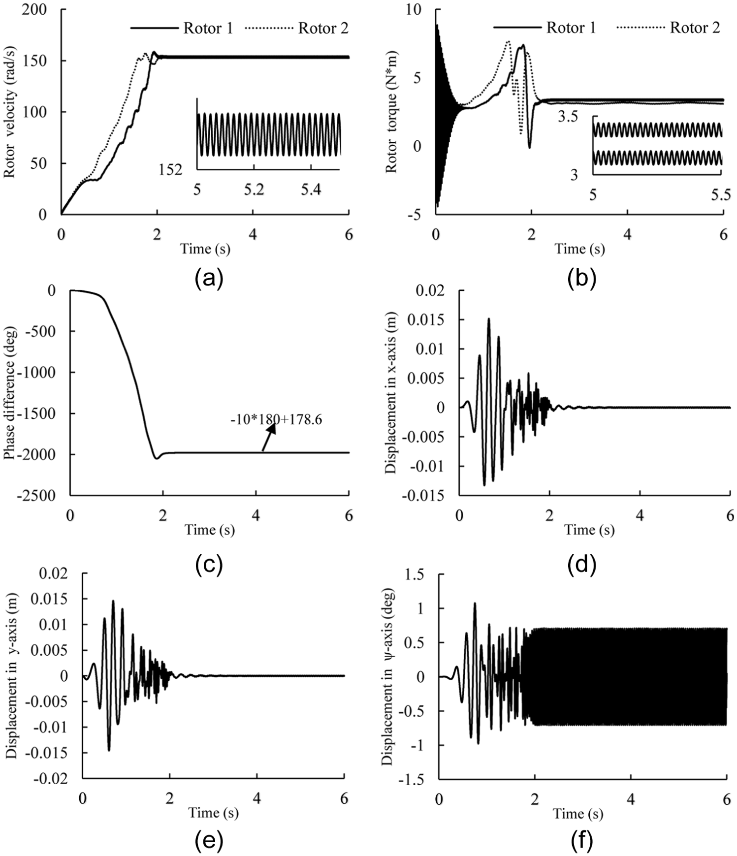
The synchronous state, considering the asymmetrical installation of the non-identical rotors, will be discussed in this section. According to Figure 4(f), it can be that the phase difference stabilizes at −180° when the second rotors installed in the mass center of the system. The dimensionless parameters rl = 2, β = 0°, δ= 0, rm = 0.02, and η = 0.25 are assumed to verify the theoretical solutions (in this case, the parameters in equations (1)–(4) are M = 80 kg, m1 = 4 kg, m2 = 1 kg, r = 004 m, l0 = 0.3 m, l1 = 0.6 m, and l2 = 0 m). From Figure 2(a), it can be seen that the parameters are located in the gray zone; therefore, the phase difference belongs to interval
Simulation results for rl = 2, β = 0°, δ= 0, rm = 0.02, and η = 0.25: (a) Rotor velocity, (b) Rotor torque, (c) Phase difference, (d) Displacement in x-axis, (e) Displacement in y-axis and (f) Displacement in
In the case, when the two rotors rotate in the synchronous state, the part energy supplied by the two induction motors is dissipated by their frictions and dampers (

In the synchronous state, the energy balance of the system, considering the asymmetrical installation of the non-identical rotors, is depicted in Figure 7(c).
Simulations for rl = 1, β = 0°, δ= 1, rm = 0.05, and η = 1
In the section, we will consider the synchronous state when the two identical rotors are symmetrically installed more closely than section “Simulations for rl = 2, β = 0°, δ= 1, rm = 0.02, and η = 1.” The values of the dimensionless parameters rl = 1, β = 0°, δ = 1, rm = 0.05, and η = 1 are supposed (in this case, the value of the parameters in equations (1)–(4) are M = 80 kg, m1 = m2 = 4 kg, r = 004 m, l0 = 0.3 m, and l1 =l2 = 0.3 m). From the theoretical computations in Figure 2(f), it is known that the value of the parameters of the system are located in the gray zone; therefore, the value of the stable phase difference belongs to interval
Simulation results for rl = 1, β = 0°, δ = 1, rm = 0.05, and η = 1: (a) Rotor velocity, (b) Rotor torque, (c) Phase difference, (d) Displacement in x-axis, (e) Displacement in y-axis and (f) Displacement in
The displacement amplitude in x- and y-directions is very small. Therefore, the energy transition (
In the synchronous state, the energy balance of the system, considering the symmetrical installation of the non-identical rotors, is depicted in Figure 7(d).
Simulations for rl = 3, β = 45°, δ = 1, rm = 0.02, and η = 1
According to Figure 4(a), it is indicated that the synphase synchronization of the two rotors can be implemented when
Simulation results for rl = 3, β = 45°, δ = 1, rm = 0.02, and η = 1: (a) Rotor velocity, (b) Rotor torque, (c) Phase difference, (d) Displacement in x-axis, (e) Displacement in y-axis and (f) Displacement in
In the case, the part energy supplied by the two induction motors is dissipated by their friction dampers (
Therefore, the energy balance of the system in the synchronous state is identical with Figure 7(c).
Conclusion
To design new vibrating screens, the synchronization phenomenon for two co-rotating rotors, interacting via the vibrating body in the far-resonance vibration system, has been investigated with the energy balance method. According to this method, the synchronous zone, synchronous state, synchronous stability, and the energy balance of the system can be determined. It is observed that the dynamic characteristics of the vibrating body are related to the synchronous state of the system. When designing the vibrating screens, the synchronous state can be chosen to acquire the desired dynamics characteristics of the vibrating screens through this method. And the synchronous state of the system is mainly determined by installation distance coefficient rl, installation angular β, symmetric coefficient δ, and electromagnetic torque Tei, while little influenced by the mass ratio η and rm. On the other hand, these theoretical investigations can be used to evaluate and discriminate whether a self-synchronous machine used in industries is able to achieve vibratory synchronization or not, as well as to supervise whether the design of a self-synchronous vibrating machine has the capacity of achieving vibratory synchronization.
Footnotes
Academic Editor: Jia-Jang Wu
Declaration of Conflicting Interests
The author(s) declared no potential conflicts of interest with respect to the research, authorship, and/or publication of this article.
Funding
The author(s) disclosed receipt of the following financial support for the research, authorship, and/or publication of this article: This study supported by the National Natural Science Foundation of China (Grant No. 51074132) and the Key Project of Talent Engineering of Sichuan, China (Grant No. 2016RZ0059).