In-phase self-synchronization of two eccentric rotors with common rotational axis is hardly implemented in far-resonance system. In this article, a dual motor coaxially coupling with a torsion spring is proposed to obtain in-phase synchronization between the eccentric rotors. To explore the dynamic and synchronous characteristics of the proposed system, the mechanical model is first established with Lagrangian formulation. Second, the steady response of the system is calculated based on differential motion equations. Subsequently, the synchronous mechanism between the eccentric rotors is discussed by averaged small parameter method. Finally, some numerical computations are further implemented to verify correctness of theoretical analysis. The result shows that the synchronous state is determined by stiffness of torsion spring, masses of eccentric rotors, and distance between the motors. When axial distance between the motor is smaller, “critical stiffness of in-phase synchronization” is gradually enlarged as the masses of the eccentric rotors are increased and approached to equality, but in-phase synchronization is permanently maintained when the axial distance of the motor is far; in this situation, the synchronous state is hardly affected by variation of stiffness of torsion spring and masses of eccentric rotors. When the stiffness of the torsion spring is smaller, “critical distance of in-phase synchronization” is also enlarged as the masses of the eccentric rotors are increased and approached to equality; otherwise, the synchronous state is always locked in in-phase synchronization. When the stiffness of the torsion spring is smaller, “critical distance of anti-phase synchronization” is decreased as the masses of eccentric rotors are increased and approached to equality; otherwise, the synchronous state is always locked in in-phase synchronization.
The phenomenon of synchronization refers to the realization of similar or identical forms of motion or physical forms of things or observed objects.1 In engineering of design and manufacture, synchronous phenomenon and synchronous issues often appear. For example, many mechanical devices used in modern industrial production require two or more working parts, such as the parts of rotating shafts,2 eccentric rotors (ERs),3 and pendulum;4 displacement speed, acceleration, phase, and applied force of the parts should be synchronized when the system is operated in steady state. With the continuous development of science and technology, synchronous machinery in metallurgy, construction materials, energy, and material screenings play an important role. Therefore, the development of the vibrating machinery will be promoted and expedited for exploring the phenomenon of synchronization in engineering. According to the study of synchronization, the synchronization can be divided into self-synchronization, synchronization control, and forced synchronization.
Self-synchronization means that the vibration system without forced device adjusts frequency of the subsystems depending on their own weak coupling characteristics, and so the frequency of these subsystems can be harmonized and unified. Self-synchronous phenomenon stems from 1665 when Huygens discovered the phenomenon of anti-phase synchronization of pendulum.5 In the 1960s, Blekhman gave the first theoretical explanation for the synchronization issue with respect to two identical ERs in a vibrating system.6 Wen and Zhao1 further developed Blekhman’s theory and proposed the integral averaging method for solving the problem of self-synchronization in screening machinery. Besides, Balthazar et al.2,7 gave some findings on synchronous rotation of two (or four) non-ideal ERs installed in a flexible construction, and synchronous state affected by case “Sommerfeld effect” was also discussed. Djanan et al.8,9 explored synchronization between three motors in a plate with periodic integration method, and the rotation behavior between the motors is obviously affected by structure size of the plate. Zhao et al.10 introduced the averaged small parameter method to explain the synchronous mechanisms of dual-exciter systems based on nonlinear dynamics, and the synchronous stability is also discussed with Routh–Hurwitz criteria. Hou and Fang11 proposed energy balance method to explore the synchronization and energy transmission of ERs in a far-resonance system, which demonstrates that the synchronization of the motors relies on their own distance. Chen et al.12 considered synchronization of two ERs with common rotational axis, and it can be found that in-phase synchronization is hardly implemented on account of the short distance between the motors in design of screening machinery. Zhang and colleagues13–15 studied the synchronization transmission of a multi-rotor in different kinds of systems, and the ideal synchronous state can be carried out in some specific conditions. M Kapitaniak et al.16 studied the synchronization of rotating pendula and compared them with the results obtained for oscillating pendula. Therefore, these self-synchronous systems are difficult to realize in-phase or ideal synchronization in practical engineering applications and the synchronous behavior is mainly determined by structure parameters of the system. How to solve the problem of self-synchronous system, synchronization control for vibrating systems is proposed to obtain the ideal synchronization state. The main controlling parameters in vibrating systems are displacement, speed, and acceleration, respectively. Huang et al.17 proposed speed and phase control to implement ideal synchronization of two ERs actuated with asynchronous motors in a nonlinear vibration system. Kong et al.18,19 gave adaptive sliding mode control algorithm to control synchronous state of three ERs in a vibrating system; to decrease the design cost, composite synchronization (self-synchronization coupled with synchronization control) for a multi-exciter system is introduced. Through investigation, the cost of controlled synchronization is far higher than self-synchronization system, the control system is approached to half price of the whole system. Therefore, forced synchronization may be a high performance–cost ratio implementing the ideal synchronization state for vibrating systems. The forced synchronization system is mainly used in gear transmission to force the frequency synchronization between the ERs in parallel axis.20 Lian et al.21 employed the harmonic tool in finite element method (FEM) software to study the dynamic stress of the gears during start and steady state, and the results show that the stress maximum in the start state is far larger than that in steady state. Stankevich et al.22 studied a model of a generator of quasiperiodic oscillations forced by a periodic pulse sequence and its forced synchronization phenomenon during the working state and found a synchronous diagram of small-scale and large-to-small-scale and large-scale structures in the forced quasiperiodic oscillations. The main reason is that the gear train suffers from greater impact loads and inertia loads, which easily induce the fatigue failure and tooth-breaking of the gears. To improve the reliability of the forced synchronization system, Fang and colleagues23,24 considered the synchronization of single ER coupled with a torsion spring and it is found that the synchronous characteristics of the system are influenced by stiffness of the torsion spring and structure parameter of the system.
The two ERs with common rotational axis in far-resonance system have been proposed by Chen. The two ERs with common rotational axis in far-resonance system have been proposed by Chen and in this model, there are no connected springs between the coaxial two ERs. Through investigation, in-phase synchronization between the ERs is hardly carried out in Chen’s model.12 In order to improve the screening efficiency of the vibrating screens used in recycle of drilling fluid in petroleum engineering by increasing in-phase synchronization capability and the excitation force of the system, a torsion spring used to connect the rotational axis of the ERs is proposed base on Chen’s model and the synchronous mechanism of this system is introduced.
Mechanical model
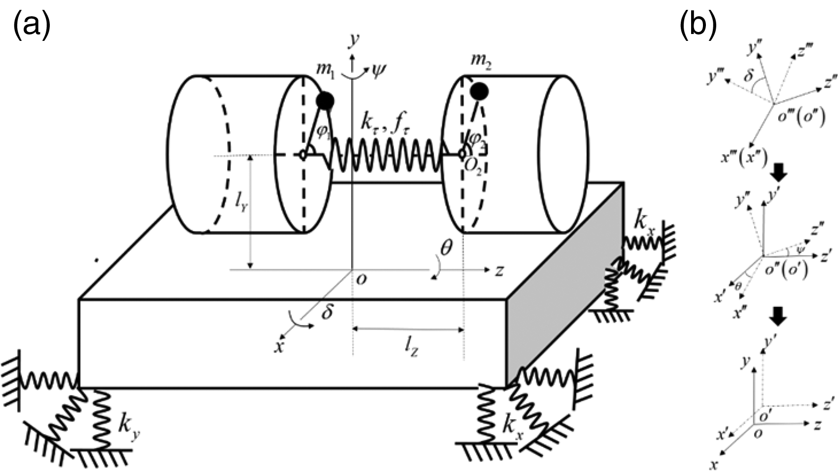
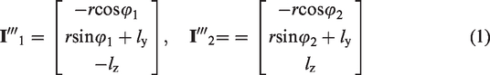
The simplified mechanical model of the proposed system is illustrated in Figure 1(a). According to the simplified mechanical model, it can be legible to identify that the system consists of four groups of supporting springs, a rigid frame, two exciters, two rotors, and a torsion spring. This vibrating system is driven by two ERs in two asynchronous motors, which are connected by a torsion spring with stiffness coefficient and damping coefficient in a common rotational axes. In this spatial system, the two ERs rotate in same direction. The rigid frame is symmetrically supported by springs with stiffness and damping in j direction . The mass of rigid frame is represented by ; the mass of ERs can be expressed as ; the eccentric radius of the ERs is defined as ; the distances between motor shaft and y- and z-axes are described as and , respectively. The transformation of the reference coordinates is shown in Figure 1(b), and conversion sequence of the reference coordinates is followed by , and is a fixed coordinate system; besides, when the system is in stationary state, the mass center of the rigid frame coincides with origin point . In this case, this rigid frame is translated in x- and y-axes, and rotated in -, -, and -axes. The phase angles of the ERs are represented by and , respectively.
Dynamical model of the vibration system: (a) dynamic model and (b) reference coordinate.
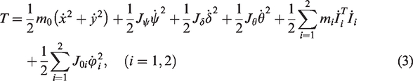
In coordinate , the centroid coordinates and of the two ERs can be denoted as
The centroid of the rigid frame is in fixed coordinate . The centroid coordinate of the ERs with respect to coordinate can be converted through rotation matrix A, that is
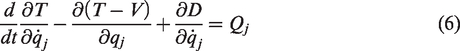
The kinetic energy of the system should be calculated as
In the formula above, the symbols of • and •• represent d•/dt and d2•/dt2, respectively. Accordingly, the rotational inertia of the rigid frame around x-, y-, and z-axes are separately defined as , , and ; consider that , , and , and are equivalent eccentricity of the rigid frame. To simplify the solution procedure for synchronous mechanism of the system, is assumed in this article. The moment of inertia of the shaft in the ith motor is denoted as .
The potential energy of the system can be calculated as
Meanwhile, the dissipated energy of this system can be expressed by
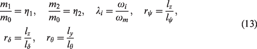
Introducing Lagrangian formulation
where is an element of generalized coordinate matrix of the system, which can be expressed as ; meanwhile, is an element of generalized force matrix , which should be considered as
where is electromagnetic torque in the motors, and is the damping moment in the motors . Substituting equations (3)–(5) and (7) into equation (6), and considering the values of the parameters , the motion equation of this system is calculated as follows
Stable response of the vibration system
Because the two motors are directly installed in the support frame, the periodic vibration of the support frame is determined by the synchronous rotation between the two ERs. Thus, the angular speed of the ERs is also periodically oscillated in the synchronization state, and the average phase of the ERs in synchronous state is assumed as . Moreover, the phase of the second rotor lagged the first can be defined as . Therefore, the phase angles of the two exciters can be written as
Then, the derivative of phase angles and related to time can be calculated; in this case, the velocity of the motors can be given as
As mentioned above, the average angular velocity of the exciters should be periodically fluctuated in period T, and so the average value of rotated speed of the ERs over single period T should be a constant, that is
where is the initial time or relative time when calculating the average value of rotated speed of the motors.
Employing method of the averaged small parameter, the coefficients of instantaneous fluctuation of and around are assigned to be and in synchronous state and is the synchronous speed of the ERs. It should be noted that the small parameters are functions with respect to t, and so speed and acceleration of the ERs should be expressed as
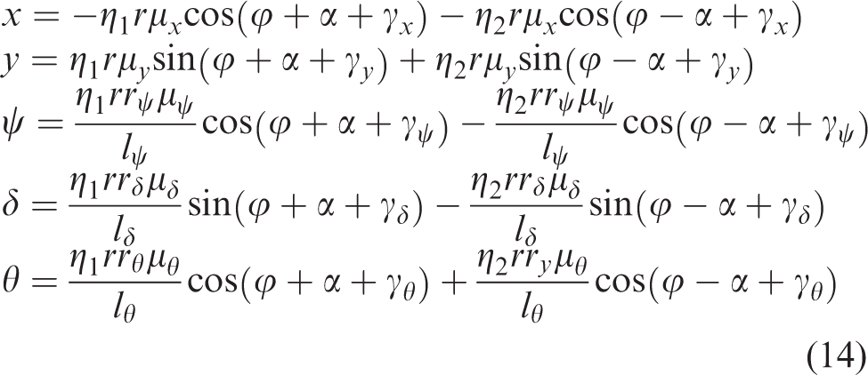
To simplify the solution process, introduce the dimensionless parameters as follows
Substituting equations (11) and (12) in to equation (8), and neglecting the small parameters, the responses of the system in axes can be expressed as
where is the amplitude amplification factor, ; is lagging phase angles in i-direction, , and , and
Synchronization mechanism
Synchronization condition
When the motors are synchronously operated, the phase difference of the ERs will be determined by condition of synchronization and criterion of synchronous stability. According to equation (9), the phase difference can be defined as
On the basis of equation (14), , and can be obtained by differentiating with respect to time t, respectively. Substituting them into differential motion equation of ERs in equation (8), and integrating the equations over single period T, the average equation of torque balance between the motors in the period can be expressed as
where
And
The fluctuation of small parameters , , , and related to time t is smaller than phase angle . In the following process of integrations, , , , , and represent their averaged values in single period T.
When the ERs are rotated in synchronous state, the electromagnetic torque of asynchronous motors in its synchronous velocity can be expressed by
where and are linearization of electromagnetic torque and stiffness coefficient related to synchronous velocity when the asynchronous motors are synchronously operated.
where is the inertial coupling matrix in the ERs, is the stiffness coupling matrix, and is the coupling matrix of load torque. The average value of small parameters and should be zero in the synchronous state, and so small parameter matrixes and are also equal to zero. Substituting and into equation (22), the elements in load torque matrix should be zero, that is
As represented in equation (24), the term of is the summation of average electromagnetic torque of the motors; the term of is the summation of averaged damping moment of the motors; the remaining terms are summation of the load torque of the motors. Thus, equation (24) describes the approximate summation of torque balance in the motor shafts when the system operated in the synchronous state, which is mainly employed to search synchronous velocity of the motors. As shown in equation (25), the term is the difference of averaged electromagnetic torque of the motors, the term is the difference of averaged damping moment between the motors, and the remaining terms are the difference of the load torque between the motors. In this situation, equation (25) represents the approximate difference of torque balance of the motor shafts when the system is synchronously operated, which is mainly used to solve phase difference between the motors.
Synchronous stability criterion
According to equation (25), two solutions of phase difference between the ERs should be obtained with computation analysis, through investigation, which is a stable value should be discussed by the Hamilton principle. Considering equations (3) and (4), Hamilton’s action quantity in periodic, represented by S, can be written as follows
Considering equation (26), substitute the first-order derivative of equation (14) related to time t into equation (26), and Hamilton’s action quantity S can be obtained by
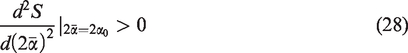
The second-order derivative of related to in equation (27) should be greater than zero, that is
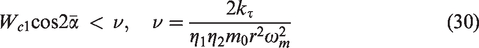
Substituting equation (27) into equation (28), the criterion of the synchronous stability is calculated by
On account of the value of parameters larger than zero, the criterion can be rewritten by
when , , the value of is in interval of . When , , the value is in interval of . Moreover, the synchronous condition cannot be satisfied by the parameters of the vibrating system when , the synchronous operation between the motors is hardly implemented.
Numerical analysis
In this section, the corresponding numerical analyses are implemented for further exploring the synchronous mechanism according to the theoretical description of the previous section. The stable phase difference is determined by condition of synchronization and criterion of synchronous stability. Therefore, the value of the parameters of the system should be satisfied by equations (25) and (30), and the obtained phase difference can be called as stable phase difference. As the same type of motor is applied in the system, the average electromagnetic and damping torque should be approximately identical, that is, and . In this case, synchronization condition can be further simplified as
This equation above is nonlinear; therefore, analytical solution of phase difference cannot be obtained. Combining with criterion of synchronous stability, one can see that the value of stable phase difference is affected by dimensionless parameters , , , and system parameters , , , and are the function of frequency ratios, damping ratios, mass ratios, and distance ratios. In this case, the stable phase difference is subjected to the mass of ERs, mass of rigid frame, eccentric radius, damping, stiffness of torsion spring, distance, and synchronous velocity between the motors. In practical engineering, the values of rigid frame mass, synchronous velocity, and eccentric radius are fixed; therefore, the synchronous state of the system influenced by rotor mass, damping, stiffness of torsion spring, and distance between the motors will be discussed.
Phase difference changed with
First, consider the distance ratios to be 0.32 and 0.98, respectively. In Figure 2(a), when value of is fixed in , the phase difference of the ERs jumps from to 0 with the increase in mass ratio of ER 1 and stiffness of the torsion spring; in this situation, the synchronous state is transited from anti-phase to in-phase synchronization. Here, stiffness of the torsion spring corresponding to jumping value of the phase difference is defined as “critical stiffness of in-phase synchronization.” Therefore, the value of “critical stiffness of in-phase synchronization” is equal to when , respectively. Figure 2(b) shows that the value of “critical stiffness of in-phase synchronization” is consistent with Figure 2(a) when is a fixed constant, which illustrates that the synchronous state cannot be affected by the symmetric alternation of mass ratios and . When the values of and are different, the closer the values of and , the larger the “critical stiffness of in-phase synchronization.” When the values of and are identical, Figure 2(c) shows that the smaller the mass ratio, the smaller the “critical stiffness of in-phase synchronization.”. In summary, when distance between the two ERs is small, the synchronous state is significantly influenced by mass ratios and stiffness of torsion springs.
Then consider the distance ratios to be 1.6 and 0.32, respectively. The stable phase difference is closed to zero when the mass ratios of the ERs are different, as shown in Figure 2(d) and (e), Through investigation, the stable phase difference is equal to zero when the mass ratios of the ERs are identical. When value of the stable phase difference is closed or equal to zero, zero-phase synchronization can be defined in the system. As a result, when distance between the two ERs is far enough, the zero-phase synchronization of the system is less influenced by the change of mass ratios of ERs and the stiffness of torsion spring.
Phase difference changed with
First, consider stiffness coefficient and distance ratio to be and 0.98, respectively. It can be seen from Figure 3(a) that the phase difference between the ERs jumps from to 0 with the increase in , , and when , and so the synchronous state is transited from anti-phase synchronous state to in-phase synchronous state. Here, the distance ratios between the exciters corresponding to jumping value of the phase difference are defined as “critical distance of in-phase synchronization.” When and , the values of “critical distance of in-phase synchronization” are equal to 0.625 and 1.02, respectively; when and , the values of “critical distance of in-phase synchronization” are identical. The values of “critical distance of in-phase synchronization” in Figure 3(b) are consistent with Figure 3(a), which also indicates that the synchronization between ERs is less affected by the symmetric alternation of mass ratios and . When the value of , is identical, Figure 3(c) shows that the smaller the mass ratio, the smaller the “critical distance of in-phase synchronization.” In summary, the far distance from the motor shaft to the y-axis, and the small mass of the ERs are in favor of in-phase synchronization achievement when stiffness coefficient is small.
Phase difference changed with : (a) , (b) , (c) , (d) , (e) , and (f) .
Then, considering stiffness coefficient and distance ratio to be 8 and 0.98, the values of “critical distance of in-phase synchronization” are decreased compared with . As shown in Figure 3(d), when and , the values of “critical distance of in-phase synchronization” are equal to zero; when and , the values of “critical distance of in-phase synchronization” are equal to 0.6 and 0.7, respectively. Figure 3(e) shows synchronization between the ERs is less affected by the symmetric alternation of mass ratios and . When mass ratios and are identical, Figure 3(f) represents that the phase difference of the system is locked in zero when mass ratios and are smaller than or equal to 0.3, and the value of “critical distance of in-phase synchronization” is 0.625 when . These findings reflect that the small mass of the ERs, and the far distance from motor shaft to y-axis are in favor of in-phase synchronization achievement in condition of large value of stiffness coefficient . Meanwhile, the values of “critical distance of in-phase synchronization” with respect to large stiffness coefficient are greater than small stiffness coefficient.
Phase difference changed with
First, consider stiffness coefficient and distance ratio to be and 0.53, respectively. The phase difference of the ERs jumps from 0 to with the increase in distance ratio ; in this situation, the synchronous state is transited from in-phase to anti-phase synchronization. Here, distance ratio corresponding to jumping value of phase difference is defined as “critical distance of anti-phase synchronization.” As shown in Figure 4(a), when , the values of “critical distance of anti-phase synchronization” are equal to 1.21, 0.80, 0.67, and 0.54, respectively. Figure 4(b) shows that synchronous state is less affected by the symmetric alternation of mass ratios and . When the values of and are identical, Figure 4(c) shows that the smaller the mass ratio, the larger the “critical distance of anti-phase synchronization.” These findings reveal that the small distance from motor shaft to z-axis, and small mass of the ERs are in favor of in-phase synchronization achievement when stiffness coefficient is small.
Phase difference changed with : (a) , (b) , (c) , (d) , (e) , and (f) .
Then, the stiffness of the torsion spring is increased to , and the values of “critical distance of anti-phase synchronization” are also increased. As shown in Figure 4(d), when , the values of “critical distance of in-phase synchronization” are equal to 2.55, 1.74, 1.48, and 1.20, respectively. Figure 4(e) also shows synchronous state of the system is less affected by the symmetric alternation of mass ratios and . According to Figure 4(f), the stable phase difference is remained at zero when , and the values of “critical distance of anti-phase synchronization” are equal to 2.55, 1.61, and 1.20 when , respectively. It is indicated that the smaller distance from the motor shaft to z-axis and smaller mass ratios of the ERs are beneficial to in-phase synchronization achievement when stiffness coefficient is large. Meanwhile, the values of “critical distance of anti-phase synchronization” of large stiffness coefficient are less than small stiffness coefficient.
Simulations
To verify the reliability and accuracy of the theoretical analysis above, it is necessary to establish an electromechanical coupling model based on the dynamics equations of system. Therefore, this section will discuss the synchronization of the system according to four samples. The values of electric parameters of the motor are considered in Table 1, and it should be noted that the power source of the motor is supplied at the same time. The structural parameters of the system are , , , , , , , , , and , , and are variables in the simulation model.
Electric parameters of the motor.
Parameters
Motor 1
Motor 2
Parameters
Motor 1
Motor 2
Rated power
0.7 kW
0.7 kW
Rotor resistance
0.06 Ω
0.06 Ω
Rated voltage
220 V
220 V
Stator inductance
0.0009 Ω
0.0009 Ω
Rated frequency
50 Hz
50 Hz
Rotor inductance
0.0009 Ω
0.0009 Ω
Rated velocity
157 rad/s
157 rad/s
Mutual inductance
0.03 H
0.03 H
Pole number
4
4
Stator resistance
0.1 Ω
0.1 Ω
Damping coefficient
0.02 N m/(rad/s)
0.02 N m/(rad/s)
Synchronization for , , and
Figure 5 shows the synchronization of the ERs as , , and . In this simulation model, and are assumed. The angular acceleration of the ERs in start state is different as the discrepancy of their rotational inertia and small stiffness coefficient of the torsion spring, as shown in Figure 5(a); in the steady state, the two motor are synchronously operated with an identical averaged velocity. In Figure 5(b), the phase difference between the ERs stabilizes at the vicinity of during the synchronous state, which is anti-phase synchronization and consistent with theoretical computation in Figure 2(a). Figure 5(c) represents that average electromagnetic torque in the motors is approximately equal to 3.6 N m, and this value is automatically and periodically fluctuated to maintain the stability of synchronous state. The translational vibration of the rigid frame is shown in Figure 5(d) and (e), and the amplitudes in x- and y-axes are 9 × 10⁻⁴ m and 9 × 10⁻⁴ m, respectively. Pitching vibration of the rigid frame is shown in Figure 5(f)–(h), and the amplitudes of the rigid frame are 6 × 10⁻³ rad, 4 × 10⁻³ rad, and 5 × 10⁻² rad, respectively. According to Figure 5(d) and (e), as amplitude of these displacements is rather small, the value of the parameters in this case is inappropriate to design the vibrating screens.
Synchronization for , : (a) velocities, (b) phase difference, (c) electromagnetic torque, (d) displacement in x-direction, (e) displacement in y-direction, (f) pitching vibration in ψ-direction, (g) pitching vibration in δ-direction, and (h) pitching vibration in δ-direction.
Synchronization for , , and
Figure 6 shows the synchronization of the ERs as , , and . In this simulation model, m and m. The angular acceleration of the ERs in the start state is identical as the larger stiffness of the torsion spring between the motors is applied, as shown in Figure 6(a), and the average rotating speeds of the motor are rad/s in the synchronous state. In Figure 6(b), the phase difference between the ERs is zero, which is different with Figure 5(a) as stronger stiffness coupling between the ERs and agreement with theoretical computation in Figure 2(d). The average electromagnetic torque is 3.55 N m closed to 3.6 N m in section “Synchronization for , , and ,” which indicates that the electromagnetic torque of the motor is little influenced by stiffness of the torsion spring. The translational vibration of the rigid frame is shown in Figure 6(d) and (e); the amplitudes in x- and y-axes are 2.8 × 10⁻³ m and 2.7 × 10⁻³ m, respectively. Pitching vibration of the rigid frame is shown in Figure 6(f)–(h), the amplitudes of the rigid frame are 1.5 × 10⁻³ rad, 1.9 × 10⁻³ rad, and 1 × 10⁻² rad in -, -, and -axes, respectively. The amplitudes of the rigid frame are far larger than that of section “Synchronization for , , and ” on account of different synchronous state; therefore, in-phase synchronization of the system is better in design of vibrating screens than anti-phase synchronization.
Synchronization for , , and : (a) velocities, (b) phase difference, (c) electromagnetic torque, (d) displacement in x-direction, (e) displacement in y-direction, (f) pitching vibration in ψ-direction, (g) pitching vibration in δ-direction, and (h) pitching vibration in δ-direction.
Synchronization , , and
Figure 7 shows the synchronization of the system as , , and . In this simulation model, m and m are assumed. The angular acceleration of the ERs in start state is identical when the center of rotation of the motor coincides with z-axis, as shown in Figure 7(a), and the synchronous speed of motors is approximated to 157 rad/s. In Figure 7(b), ERs are operated in in-phased synchronization, which is agreement with theoretical result in Figure 4(a). Figure 7(c) represents average electromagnetic torque in the motors is approximately equal to 3.57 N m. Through investigation, the fluctuation of the electromagnetic torque is far feebler than that explained in sections “Synchronization for , , and ” and “Synchronization for , , and ” on account of small amplitude of the pitching vibrations. As shown in Figure 7(d) and (e), the amplitudes in x- and y-axes are 2.9 × 10⁻³ m and 2.8 × 10⁻³ m, respectively. Pitching vibration of the rigid frame is shown in Figure 7(f)–(h), the amplitudes of the rigid frame are 3 × 10⁻³ rad, 3 × 10⁻³ rad, and 0 rad, respectively. It is indicated that the in-phase synchronization can be implemented when the distance between the motor shaft and z-axis is zero.
Synchronization for , , and : (a) velocities, (b) phase difference, (c) electromagnetic torque, (d) displacement in x-direction, (e) displacement in y-direction, (f) pitching vibration in ψ-direction, (g) pitching vibration in δ-direction, and (h) pitching vibration in θ-direction.
Synchronization for , , and
Figure 8 shows synchronization of the system for and . In this simulation model, m and m. The angular acceleration of the ERs in the start state is different as the far distance between the motor shaft to z-axis, as shown in Figure 8(a), and synchronous speed of the motors is approximated to 157 rad/s. In Figure 8(b), it is indicated that the ERs are operated in in-phased synchronization, which is agreement with theoretical result in Figure 4(a). Figure 8(c) represents average electromagnetic torque in the motors is approximately equal to 4.7 N m, and the value is larger than the first three cases because of large value of parameter . As shown in Figure 8(d) and (e), the amplitudes in x- and y-axes are 9 × 10⁻⁴ m and 0.9 × 10⁻⁴ m, respectively, which is coincident to section “Synchronization for , , and .” Pitching vibration of the rigid frame is shown in Figure 8(f)–(h), the amplitudes of the rigid frame are 3 × 10⁻³ rad, 3 × 10⁻² rad, and 0 rad, respectively. It is indicated that the anti-phase synchronization can be implemented when the distance between the motor shaft and y-axis is far enough.
Synchronization for , , and : (a) velocities, (b) phase difference, (c) electromagnetic torque, (d) displacement in x-direction, (e) displacement in y-direction, (f) pitching vibration in ψ-direction, (g) pitching vibration in δ-direction, and (h) pitching vibration in θ-direction.
Conclusion
Through studying the synchronous mechanism of the dual-exciter vibration system coupling through a torsion spring, the following important conclusions should be stressed:
The synchronous behavior of this system is mainly determined by the stiffness of torsion spring, the installation distance between the motors, and the mass of the ERs.
When the axial distance between the motor is smaller, the “critical stiffness of in-phase synchronization” is gradually enlarged as the mass of the ER is increased and approached to equality. Through investigation, in-phase synchronization is always maintained when the axial distance of the motor is far; in this situation, the synchronous state of the system is hardly affected by stiffness of torsion spring and mass of ERs.
When the stiffness of the torsion spring is smaller, the “critical distance of in-phase synchronization” of the system is also enlarged as the masses of the rotors are increased and approached to equality; otherwise, the synchronous state is always locked in in-phase synchronization.
When the stiffness of the torsion spring is smaller, the “critical distance of anti-phase synchronization” of the system is decreased as the masses of the ERs are increased and approached to equality; otherwise, the synchronous state is always locked in in-phase synchronization.
Footnotes
Handling Editor: James Baldwin
Declaration of conflicting interests
The author(s) declared no potential conflicts of interest with respect to the research, authorship, and/or publication of this article.
Funding
The author(s) disclosed receipt of the following financial support for the research, authorship, and/or publication of this article: This work was supported by the National Natural Science Foundation of China (Grant No. 51705437), Chinese Postdoctoral Fund (Grant No. 2019M653482), Strategic Cooperation Project of Science and Technology between SWPU and Nanchong (Grant No. 18SXHZ0016), Scientific Research Starting Project of SWPU (Grant No. 2017QHZ009).
ORCID iD
Yongjun Hou
References
1.
WenBCZhaoCY.Vibratory synchronization and controlled synchronization in engineering.
Beijing, China:
Science Press, 2009.
2.
BalthazarJMFelixJLPBrasilR, et al.
Some comments on the numerical simulation of self-synchronization of four non-ideal exciters. Appl Math Comput2005;
164: 615–625.
3.
LiYJRenTZhangJN, et al.
Synchronization of two eccentric rotors driven by one motor with two flexible couplings in a spatial vibration system. Math Probl Eng2019;
2019: 2969687.
4.
CzolczynskiKPerlikowskiPStefanskiA, et al.
Synchronization of pendula rotating in different axes. Commun Nonlin Sci Numer Simul2012;
17: 3658–3672.
5.
HuygensC.Horologium oscillatorium.
Paris:
Apud F. Muguet, 1673.
6.
BlekhmanI.Synchronization in science and technology.
New York:
ASME Press, 1988.
7.
BalthazarJMFelixJLPBrasilRMLRF.Short comments on self-synchronization of two non-ideal sources supported by a flexible portal frame structure. J Vib Control2004;
10: 1739–1748.
8.
DjananAANNbendjoBRNWoafoPJMRC.Electromechanical control of vibration on a plate submitted to a non-ideal excitation. Mech Res Commun2013;
54: 72–82.
9.
DjananAANNbendjoBRNWoafoPJMRC, et al.
Effect of self-synchronization of DC motors on the amplitude of vibration of a rectangular plate. Europ Phys J Spec Top2014;
223: 813–825.
10.
ZhaoCYZhangYZhangX.Synchronisation and general dynamic symmetry of a vibrating system with two exciters rotating in opposite axes. Chinese Physics B2010;
19: 030301.
11.
HouYJFangP.Synchronization and stability of two unbalanced rotors with fast antirotation considering energy balance. Math Probl Eng2015;
2015: 694145.
12.
ChenXZKongXXZhangXL, et al.
On the synchronization of two eccentric rotors with common rotational axis: theory and experiment. Shock Vib2016;
2016: 6973597.
13.
ZhangXLWenBCZhaoCY.Vibratory synchronization transmission of a cylindrical roller in a vibrating mechanical system excited by two exciters. Mech Syst Signal Pr2017;
96: 88–103.
14.
ZhangXLLiCWangZH, et al.
Synchronous stability of four homodromy vibrators in a vibrating system with double resonant types. Shock Vib2018;
2018: 9641231.
15.
ZhangXLWenBCZhaoCY.Theoretical study on synchronization of two exciters in a nonlinear vibrating system with multiple resonant types. Nonlin Dynam2016;
85: 141–154.
16.
KapitaniakMCzolczynskiKPerlikowskiP, et al.
Synchronous states of slowly rotating pendula. Phys Report2014;
541: 1–44.
17.
HuangZSongGLiY, et al.
Synchronous control of two counter-rotating eccentric rotors in nonlinear coupling vibration system. Mech Syst Signal Proce2019;
114: 68–83.
18.
KongXXZhangXLChenXZ, et al.
Synchronization analysis and control of three eccentric rotors in a vibrating system using adaptive sliding mode control algorithm. Mech Syst Signal Pr2016;
72–73: 432–450.
19.
KongXXZhangXLChenXZ, et al.
Phase and speed synchronization control of four eccentric rotors driven by asynchronous motors in a linear vibratory feeder with unknown time-varying load torques using adaptive sliding mode control algorithm. J Sound Vib2016;
370: 23–42.
20.
YaoYSSongHNFengZX.Experiment on double-frequency composed vibrating screen. China J Highway Transp2008;
21: 122–126 (in Chinese).
21.
LianWZhangLJunYZ, et al.
Transient process response analysis of forced synchronous elliptical vibrating screen. Adv Mat Res2010;
180–182: 962–966.
22.
StankevichNVKurthsJKuznetsovAP.Forced synchronization of quasiperiodic oscillations. Communications in Nonlinear Science and Numerical Simulation2015;
20: 316–323.
23.
FangPHouYJ.Synchronization characteristics of a rotor-pendula system in multiple coupling resonant systems. Proc IMechE, Part C: J Mechanical Engineering Science2018;
232: 1802–1822.
24.
FangPHouYJDuMJ.Synchronization behavior of triple-rotor-pendula system in a dual-super-far resonance system. Proc IMechE, Part C: J Mechanical Engineering Science2019;
235: 1620–1640.