
Abstract
This article presents numerically efficient computational models for solving exemplary problems of parametric optimization with the use of the finite element method. Building computational models involved applying a non-standard usage of superelements. In the problems of static analysis, static condensation method was used for model reduction. In the case dynamic problem, component mode synthesis method was applied. The advantages of the adopted modelling methodology were shown with reference to the time required to find the optimal solution. The issue, so far overlooked in this type of analyses, of the relationship between the modelling methodology and the size of the files generated during the analysis was also mentioned.
Introduction
Numerical efficiency of a finite element (FE) model is of key importance when solving a parametric optimization problem. The search for the optimal solution is an iterative process which, for complex FE models and complex analyses of, for example, models with material, physical, or geometric nonlinearities, requires involvement of considerable computational resources (CPU time and memory size). In subsequent iterations, intermediate solutions are determined by solving each time a problem of structural, modal or dynamic analysis. The execution of a single iteration is usually associated with the need for time-consuming remeshing. Therefore, there is constant search for the ways to increase numerical efficiency of FE models which would enable to achieve the result in acceptable time. Frequently, for the purpose of such an analysis, the model is simplified, and the aim is to introduce such changes in the values of the problem variables so as to reduce the need to rebuild the node mesh of the model in subsequent iterations and to use the results of the previous iterations in the best possible way. Simplifications based on geometric properties of the analysed objects are commonly used. At our disposal, there are primarily symmetry and anti-symmetry constraints and, for axisymmetric problems, cyclic symmetry constraints are successfully applied. Moreover, it is necessary to mention submodelling. 1 Then, the defined problem is first solved based on coarse mesh, and the next step is to examine finely meshed submodels, that is, the key areas of the model. Afterwards, cut-boundary displacements are interpolated with the use of shape function and treated as boundary conditions for the submodel.
In addition, such modelling methods are applied which enable to reduce the size of the problem (the number of degrees of freedom of the model) by reducing the number of nodes in the model. Static problems can use a known technique of the number of degrees of freedom reduction, called static condensation, which leads to modelling with the use of the so-called superelements (superelement is a fragment of FE model which consist of a set of FEs treated as one new element). The complex computational problem in question is broken down into a series of smaller subproblems that can be solved independently involving much fewer computing resources. Dynamic calculations require significantly longer calculation time than static analysis. The process of solving the initial problem is an iterative process (e.g. integration of equations of motion with a set time step). The number of iterations necessary to obtain the result is naturally dependent on, among others, the size of the problem (the number of degrees of freedom of the discrete model), integration step and type of model nonlinearities. One of the commonly used methods of reducing the number of degrees of freedom of the model is the use of the method implemented in most FE commercial packages, called component mode synthesis (CMS), formulated by Craig and Bampton, 2 which is the extension of the Guyan method. 3
Examples of modelling with the use of superelements for static problems as well as the use of the reduction (condensation) method for solving dynamic problems can be found in works concerning various areas of technology. These are, for example, problems related to beam, 4 plate 5 and shell 6 vibrations; contact problems modelled with the use of superelements; 7 the analysis of strength and dynamic properties of the reactors 8 and building structures; 9 design in the automotive industry;10,11 and simulation of technological processes. 12 The major part of studies refers to the problems on the border of a few fields such as solid and fluid mechanics.13,14
Due to a large variety of reduction methods and their applications, the presented overview is incomplete. However, it points to the problem as a current one. It is worth noting that the cited works do not undertake the problem of using model reduction methods in parametric optimization tasks. It is, therefore, important to answer the question whether building the reduced model is a reasonable action from the point of view of benefits that can be obtained by solving an optimization problem. In particular, it may be beneficial to apply superelements for modelling objects with repetitive fragments for which it is possible to define the so-called secondary superelements.
Methodology of solving optimization problems
This work is meant to be a study of the efficiency of the use of static condensation method and dynamic CMS condensation method in solving a parametric optimization problem with the use of the FE method. This work presents exemplary computational models for finding optimal dimensions of carding machine (textile machine) components, particularly of the working cylinder and the comb taking off the web (a semi-finished textile product, a thin fibre layer with the width equal to the carding machine working width). These are the components which, due to their construction, are well suited for modelling with the use of secondary superelements. This work will show the solutions of the same problem using full and reduced models with application of the above-mentioned methods of problem size reduction. The assessment will concern both the quality of solutions and model numerical efficiency. In addition, the object of discussion will be the issue so far overlooked in this type of analyses, concerning the relation between the applied modelling methodology and the size of the files generated during the analysis. The author’s experience with this issue shows that frequently in the analysis of large models, the key element for the success of calculations is not so much computing time as the size of the required computer memory.
In order to solve optimization task, it is proposed to apply a calculation model of superelements used in a non-standard way. Typically, the use of condensation methods in the analysis amounts to a single determination of master and slave nodes of the model and calculating appropriate stiffness, masses and, possibly, damping matrices of a superelement. This process is generally time-consuming. However, such matrices can be later used repeatedly, for example, for analyses with a modified load or changed boundary conditions, without the need for recalculation and inversion. Obviously, the time of solving the problem, which will use the reduced matrices, is then shorter than the time required to analyse the full model.
In this article, the course of the reduction process is different, which is shown by the highlighted part in Figure 1. The essence of the original idea lies in the fact that the appropriate matrices for the superelement, together with the definition of the master and slave nodes of the model, are renewed at each iteration when solving an optimization problem (according to the changes in decision variables values). The resulting superelement is then duplicated k times. Having solved the whole problem of which the model is the sum of k superelements, depending on the needs, two options are possible:
For each k number of superelements, a subproblem is solved (YES);
Solutions of subproblems are not carried out (NO).

Block diagram of optimization problem for models with superelements.
In both cases, the process of solving parametric optimization problem is expected to accelerate, whereas in the second case, when the solution obtained only for the master nodes could be satisfactory (option 2), the benefit is likely to be much bigger.
The proposed course of action can be applied in problems that use static condensation and those for which the proper way of model reduction is dynamic condensation, in particular, the CMS method.
To compare, solutions of optimization problems are presented for full models of the discussed objects with the analysis carried out in a standard way, as shown in Figure 2.

Block diagram of optimization problem for full models.
All calculations were carried out using ANSYS package. Adequate input files were written using ANSYS Parametric Design Language (APDL) command language, by means of which a parametric model was developed for the analysed constructions together with the analysis of the calculation results and formulation of the optimization problem. The optimization problem was solved using subproblem approximation method. 1
To assess the effectiveness of the adopted procedure, a script operating in Windows Power Shell interpreter was developed. The script monitors the size of the working folder of the ANSYS package in the real time and at the same time noting calculation time. The calculations were performed on a computer with an Intel® Core™ i7-4770 (3.4 GHz) and 16 GB of memory.
Examples of parametric optimization
Analyses were performed for the carding machine (Figure 3) with the working width of 2540 mm, used in wool carding system.

Technological scheme of the carding machine.
The two main components, namely, the main cylinder and doffing comb, were considered. Without looking into the intricacies of textile technology, one can formulate the following requirements for these devices (Figure 3):
The size of the gap between the main cylinder and cooperating rollers (worker, stripper and doffer) should, depending on the type of the processed raw material, be
It is required that at the frequency of 2000/2500 oscillations/min, it is possible to maintain the size of the gap between the edge of the vibrating doffing blade and the doffer in the range of
Due to the desired web uniformity, gap shape should in both cases be similar to a rectangle. These requirements will be the basis for formulating parametric optimization problems whose solutions with the use of FE models with superelements will be discussed later in this article.
Example 1: the main cylinder of the carding machine
As of 1990s, working cylinders with reinforcement rings have been used in roller carding machines. The construction of a typical working cylinder is shown in Figure 4. It consists of a shell rolled of sheet metal and welded along the edges, bottoms welded of sheet metal with reinforcements, shaft and reinforcement rings in the form of rolled sections with a C-shaped cross section.

Construction of carding machine’s main cylinder.
Clothing in the form of saw wire is reeled coil to coil on the working cylinder, which is schematically shown in Figure 5. In reality, wire coils are pushed against one another and rest on the so-called boundary wire.
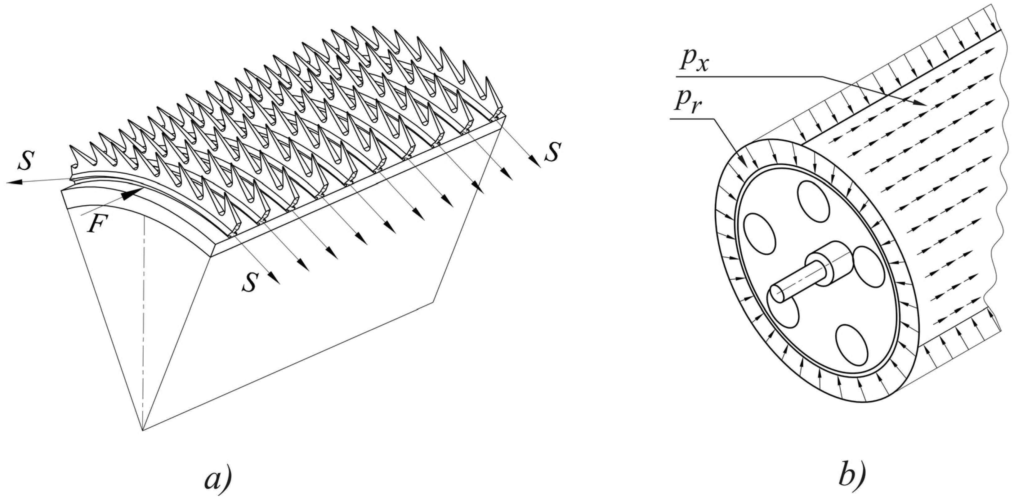
Forces acting on the cylinder clothing during reeling of saw wire.
Pressures
The analysis of the cylinder shell deflection line carried out for various forms of bottom constructions
15
shows that a significant reduction in the amplitude of deflection

Deflection of the shell of the cylinder with bottoms with a conical ring.
Therefore, further analyses, including formulation and solving optimization problem, will be shown for the cylinder with bottom with a conical ring.
FE model of the cylinder
Due to the efficiency of solving parametric optimization problem which consists in the search for the optimal shape and dimensions of the cylinder, a computational model based on the cylinder sector including one repeatable fragment of the construction (Figure 7) was prepared for the analysis.

Discrete model of the cylinder sector.
The model was developed for the ANSYS package using Shell 181 and Beam 188 elements. The Shell 181 element was used to model the shell of the cylinder and bottoms. Beam 188 element was used for modelling reinforcements. Since in the real construction, the edge of the bottom contacts the shell on a certain surface, constrained equations (coupling) were introduced in the model connecting each node on the circumference of the bottom with the adjacent nodes on the cylinder shell.
Using the discussed model of the cylinder sector, a single superelement (Matrix50 library element) was defined. Stiffness and mass matrices were written for the superelement. The master nodes were defined on the edges along which particular superelements will be coupled (Figure 8(a)). Figure 8(b) shows the cylinder model consisting of k secondary superelements with the shaft modelled with Beam 188 elements having cross-sectional parameters resulting from technical documentation. The shaft was supported by roller support on the left and hinged support on the right in the places of its bearing. Individual superelements were interconnected by means of constrained equations (coupling).

Cylinder computational model built of superelements: (a) model master nodes and (b) complete cylinder model.
Optimization problem
As previously mentioned, the optimization criterion should be the amplitude of cylinder deflection. Therefore, the objective function was assumed as

Decision variables in optimization task.
Calculation results
Numerical tests were conducted for 12 cylinder constructions different as to the number of inspection holes in the bottom n and the number of reinforcement rings N. The results obtained from solving an identical problem for the reduced and full models of the cylinder which was formed by duplicating the sector shown in Figure 7 were compared. When solving optimization tasks using the reduced model for each of k defined superelements, a subproblem was solved (see Figure 1), and the maximum amplitude of deflection was determined.
Table 1 shows the maximum values of deflection amplitudes of the analysed cylinders
Maximum amplitude of deflection
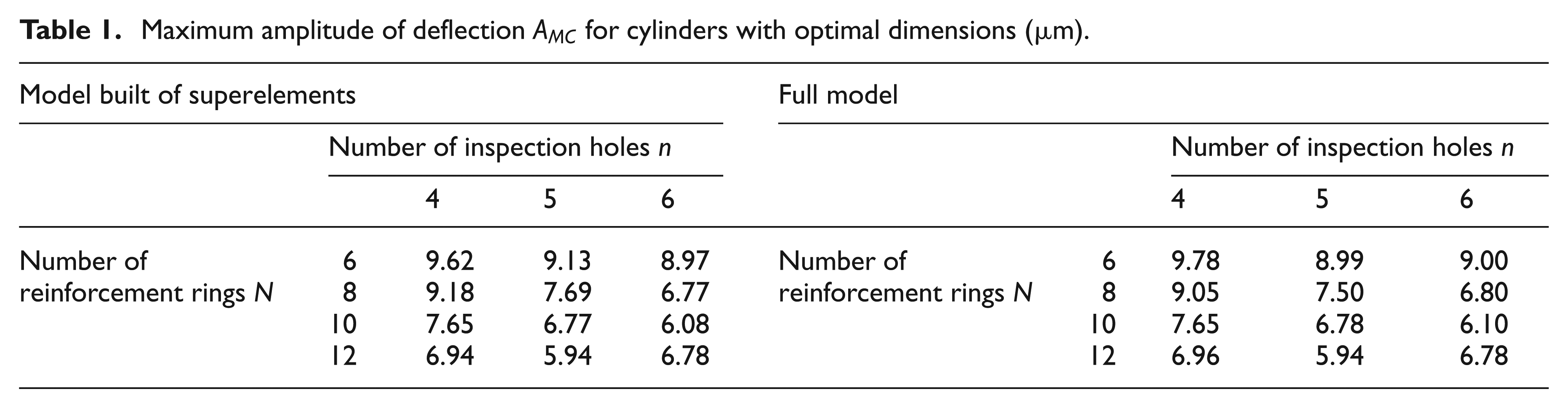
Figure 10 shows the size of the working folder of the ANSYS package versus total calculation time when solving all 12 optimization problems. Since in each corresponding case, the number of iterations required for determining the optimum was the same, the comparison is a measure of the adopted procedure efficiency.

Total memory size versus calculation time during the cylinder optimization.
As a result, it can be concluded that in order to find the best constructional form of the cylinder with optimal dimensions using superelements, 1184s were required compared to 1485s for the analysis of the full model. Unfortunately, the size of the files saved during the analysis increased from 6 GB to over 9 GB. From the point of view of numerical efficiency, the result is ambiguous. Although computation time was reduced by over 20%, memory size increased by 50%. This result can be explained by the fact that the number of nodes for a single superelement in the analysed FE model is relatively large. It makes up, depending on the case concerned, 17.3%–26% of the number of nodes for the full model. As shown in Danielczyk16,17 a significant acceleration of calculations, while reducing the required size of computer memory, takes place when the memory is smaller. For calculations performed on popular workstations, the above-mentioned value should not exceed 10%.
The solution of the optimization problem brought a significant reduction in the amplitude of deflection by nearly 63% on average with respect to the initial solutions. Figure 11 shows a deflection line of the cylinder with optimal dimensions (N = 12, n = 5), for which the maximum deflection amplitude value is 5.94 µm and is the smallest of all analysed constructional forms of the cylinder (see Figure 6).

Deflection line of the cylinder with optimal dimensions.
Example 2: doffing comb taking off the web
The device with an undivided comb was analysed (Figure 12). The right and central supports (divided) as well as the carrying pipe and comb box are the suspending construction. A series of columns, which link the shaft to the blade, was mounted on the shaft. The crank–rocker mechanism built in the comb box converts rotary motion of the drive motor into oscillating rotation of the comb shaft.

Undivided doffing comb.
Comb shaft movement is accompanied by vibrations of the blade adversely affecting the shape and size of the gap
When taking off the web, there appear reaction forces (tangential to the surface of the doffer) which are the result of fibres taken off from the doffer by the blade. The values of these forces, however, are small compared to the forces of inertia resulting from the rotational–oscillating motion of the shaft.
Calculation model
To determine the optimal size of the doffing comb, a parameterized, efficient computational model was built for solving an optimization problem of the blade and shaft cross section. The model preparation included only shaft deformation, and the suspending construction was treated as rigid (carrying pipe is nearly 80 times stiffer for bending than the shaft). Moreover, the model omitted insignificant fillets, and all screw joints were treated as non-deformable. The comb model was developed basing on the models of those parts of the comb shaft for which it is possible to define superelements. The analysis used two types of superelements (Superelement_1 and Superelement_2) defined, respectively, for the extreme part of the comb and the repeatable fragment of its central part (Figure 13).

Method of dividing into superelements.
Discrete model for the definition of a single superelement (Figure 14(a)) was built using the elements: Solid 185 for discretization of the column and doffing blade and Beam 188 for the comb shaft. Solid 185 is a 10-node solid element with 3 degrees of freedom in each node, whereas Beam 188 is a two-node beam element described in the previous example. Massless beam elements Beam 188, whose cross-sectional parameters ensured their rigid connection, were used to connect the shaft and column. Modelling included particularly careful mapping of the blade shape due to the significant impact of its mass moment of inertia and stiffness vibration amplitude. The model master nodes were defined in places of superelements interconnection as well as in the nodes of the shaft and at the edge of the doffing blade (Figure 14(b)).

Discrete model of a single superelement (Superelement_1): (a) discretization method and (b) master nodes determination.
Performing a series of auxiliary tests, it was assumed that the CMS analysis, for both defined superelements, will consider the first 10 forms of free vibrations. The complete computational model of the comb is shown in Figure 15. Superelements which had been previously defined were duplicated (mirror reflection –Superelement_1 and copies –Superelement_2) and then interconnected by means of constrained equations (coupling). The conditions of comb shaft support result directly from the way of its bearing.

Comb model composed of superelements.
The frequency of comb oscillation of 2500 cycles/min was assumed for the analyses. Due to the large excess of engine torque over the demand for the device drive, kinematic input function was assumed for calculations. Oscillating rotary motion was obtained by giving, in subsequent points in time, rotation of the last comb shaft node according to the function resulting from the kinematic analysis of the drive mechanism. Newmark method with automatic selection of integration step 18 implemented in the ANSYS package was applied for direct integration of equations of motion.
Optimization problem
Presuming that any deviation from the assumed (theoretical) trajectory of the points on the doffing blade edge should be regarded as undesirable (requiring elimination or at least reduction), the objective function was written as (Figure 16)

where δ is the deviation of the trajectory of the doffing blade end in a mobile local coordinate system

Doffing blade and doffer cooperation.
For practical evaluation of the doffing blade vibrations, normal component
Decision variables in the optimization problem are dimensions characterizing the shape of the blade cross section: a, b, h and the inner diameter of the shaft d (Figure 17). The proposed method of blade cross-sectional parameterization and the ranges of decision variables make it possible to analyse the impact of both the shape and dimensions of the blade cross section on the amplitudes of vibration. Initial values of the variables were the dimensions in accordance with the technical documentation of the doffing comb.
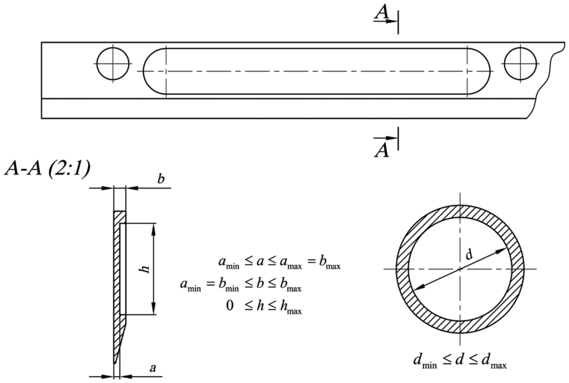
Decision variables in optimization task.
Calculation results
As in the case of the main cylinder analysis, numerical tests were carried out for the full comb model whose discretization was performed in the same way as for the model of a single superelement (see Figure 14) and for the reduced model in Figure 15. During the analysis of the full model, one more iteration was performed since the full and reduced models do not give exactly the same results. The differences do not exceed 3%. However, when compared with the criteria of stopping optimization algorithm, the result was the need to perform additional iteration. Nevertheless, the optimum values of the objective function Q obtained for the two models differ by 1.9%.
To assess the efficiency of the proposed computational model, a graph was made (Figure 18) showing the consumption of computing resources, that is, the time of calculation and the size of the memory used during calculations. The result for the full model is shown in Figure 18(a). In contrast to the previous example, solving the problem of searching the optimum dimensions of the blade and the shaft does not require solving subproblems for individual k superelements. All values in question can be obtained from the master nodes of the model (option 2, Figure 1). Then, computation time for the reduced model is almost 9 times shorter and the size of the working folder almost 215 times smaller than for the full model analysis (Figure 18(b)). To compare, in Figure 18(c), the same values were marked as in the case in which all subproblems had been solved (option 1, Figure 1). Then, computation time was 5 times shorter and the size of the working folder decreased 20-fold.

Disk resource consumption versus the total calculation time during comb optimization: (a) full model, (b) the CMS model – solutions for the master nodes and (c) the model CMS – complete solution.
Figure 19 shows the envelope of doffing blade vibrations determined in the direction normal to the intended trajectory of motion xn (the envelope of subsequent positions of the nodes lying on the edge of the blade, Figure 14). It should be noted that the maximum value of the normal component of vibrations
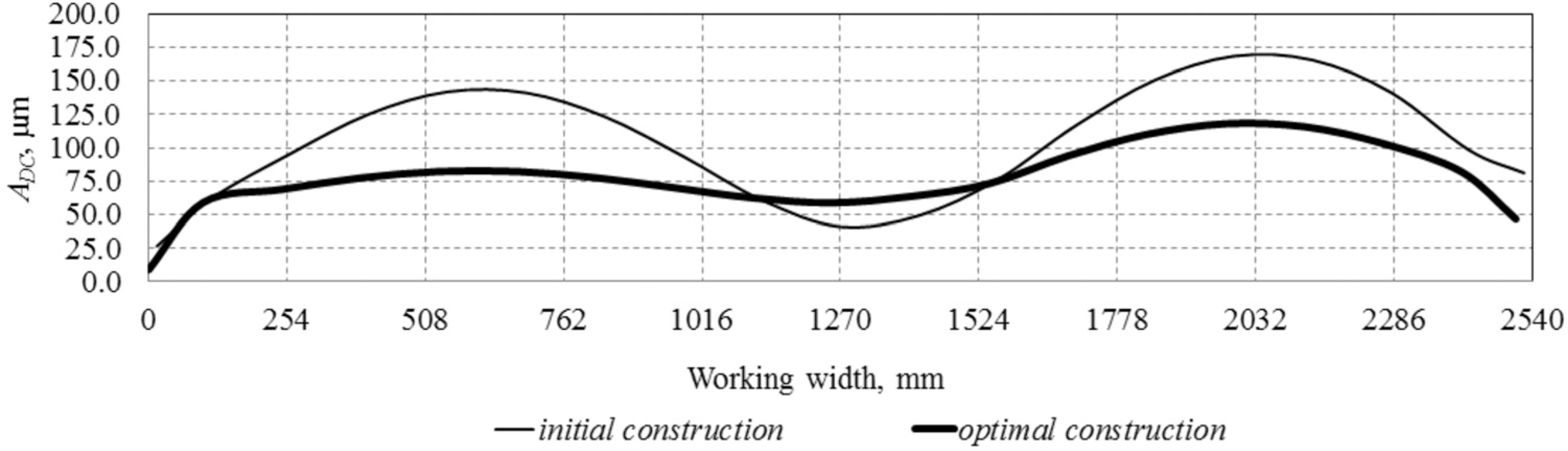
Envelope of blade vibrations for initial and optimal solutions.
Conclusion
Using a method for computational model reduction when solving a parametric optimization problem has led to tangible results as follows:
For the carding machine cylinder, the use of superelements in the FE model resulted in shortening calculation time by approximately 20%;
For the doffing comb, the use of dynamic reduction methods brought ninefold acceleration of calculations.
The analysis of the doffing comb dynamics with the use of the full model required almost 1 TB of free disk space. The model reduction resulted in 215-fold decrease of the size of the files generated during the analysis. During optimization of the main cylinder, the size of files generated during calculations increased from 6 to 9 GB, which as noted earlier is mainly due to the size of a single superelement in relation to the size of the model and the need to solve subproblems. As also noted before, acceleration of calculations, while reducing the required size of computer memory, occurs when the number of nodes for a single supplement does not exceed 10% of the full model number of nodes.
It should be emphasized that these advantages did not affect the quality of the obtained solution. Discrepancies for the objective function during cylinder optimization did not exceed 2.5%. For the comb optimization, the differences are even smaller and are 1.9%. It should also be noted that preparation of reduced computational models is not much more complicated than developing full models. It merely requires the knowledge of modelling techniques with the use of superelements.
Footnotes
Academic Editor: Shan-Tung Tu
Declaration of conflicting interests
The author(s) declared no potential conflicts of interest with respect to the research, authorship and/or publication of this article.
Funding
The author(s) received no financial support for the research, authorship and/or publication of this article.