
Abstract
This article presents generalized finite element formulation for plastic hinge modeling based on lumped plasticity in the classical Euler–Bernoulli beam. In this approach, the plastic hinges are modeled using a special enrichment function, which can describe the weak discontinuity of the solution at the location of the plastic hinge. Furthermore, it is also possible to insert a plastic hinge at an arbitrary location of the element without modifying its connectivity or adding more elements. Instead, the formations of the plastic hinges are achieved by hierarchically adding more degrees of freedom to existing elements. Due to these features, the proposed methodology can efficiently perform the first-order plastic hinge analysis of large-frame structures. A generalized finite element solution technique based on the static condensation scheme is also proposed in order to reduce the computational cost of a series of linear elastic problems, which is in general the most time-consuming portion of the first-order plastic hinge analysis. The effectiveness and accuracy of the proposed method are verified by analyzing several representative numerical examples.
Keywords
Introduction
It is well known that not a small number of structural collapse accidents have been occurring all over the world, and their main causes are natural and man-made disasters such as earthquakes, tsunamis, hurricanes, and terrorist attacks. A large number of civilian casualties and serious damage to properties are resulted in, as already have been observed in, for examples, Alfred P. Murrah federal building collapse in the United States in 1995, 1 Taiwan earthquake in 1999, 2 and Chile earthquake in 2010. 3 Therefore, it is very important to minimize the structural damages by these types of disasters and design structures that can effectively resist excessive loadings induced by them.
The use of numerical analysis methodologies such as the finite element method (FEM) is a very effective way to achieve these goals, and their importance has been increasing with the help of the recent rapid development of cutting-edge information technologies. It is possible to utilize massively parallel computing machines for obtaining accurate simulation results. However, it is more important to develop an efficient numerical methodology that can accurately simulate the collapse of building structures by consuming a relatively small amount of computational cost.
In general, the collapse of building structures is simulated by the successive formation of plastic hinges in the frame structure. Figure 1 illustrates an example of the progressive collapse of a building structure due to column loss, which frequently occurs in the structural collapse caused by explosion. 4 As another example, Figure 2 shows the progressive collapse of a frame structure subjected to earthquake excitation. 5 In this case, a large amount of internal bending moment is concentrated at the lower level of the structure, and it may lead to the sidesway failure mechanism as shown in the figure.

Progressive collapse of a building structure due to column loss.

Progressive collapse of a building structure due to earthquake excitation.
The plastic hinges can be modeled based on either lumped or distributed plasticity. The lumped plasticity model ideally assumes that plastic deformation is concentrated only at the location of plastic hinges and thus the plastic hinges can be described as an internal pin. The deformed shape of a frame member is continuous at the plastic hinge, but its derivative becomes discontinuous. The limit capacity of the plastic hinge is kept constant in the classical limit analysis, but it is possible to take into account the so-called softening plastic hinge concept with post-peak structural response as discussed in the work of Armero and Ehrlich,6,7 which introduces the embedded discontinuity with local dissipative mechanism. This approach was subsequently applied to perform the collapse simulation of reinforced concrete 8 and steel frames.9,10
In the distributed plasticity model, the member cross-section is composed of a number of fibers with axially nonlinear material properties, and the plastic deformation is spread over a certain length of the member near the plastic hinge, which is called a yield zone. 11 As a result, there exists a strong gradient in the deformed shape of the member, but no discontinuity. Although the lumped plasticity model has limitation in accurately describing plastic deformation within a member, it is much simpler than the distributed plasticity model and can predict the overall collapse failure of a frame structure in the form of the first-order plastic hinge analysis. 12
This study presents a generalized finite element formulation for plastic hinge modeling based on lumped plasticity in the classical Euler–Bernoulli beam. In this approach, the plastic hinges are modeled using a special enrichment function, which can describe the weak discontinuity of the solution at the location of the plastic hinge. Furthermore, it is also possible to insert a plastic hinge at an arbitrary location of the element without modifying its connectivity or adding more elements. Instead, the formations of the plastic hinges are achieved by hierarchically adding more degrees of freedom (DOFs) to existing elements. Due to these features, the proposed methodology can efficiently perform the first-order plastic hinge analysis of large-frame structures. A generalized finite element solution technique based on the static condensation scheme is also proposed in order to reduce the computational cost of a series of linear elastic problems, which is in general the most time-consuming portion of the first-order plastic hinge analysis. This technique is similar to the one proposed by Gupta et al. 13 The effectiveness and accuracy of the proposed method are verified by analyzing several representative numerical examples.
The outline of this article is as follows. Section “Plastic hinge modeling using the GFEM” discusses the plastic hinge modeling based on lumped plasticity using the generalized finite element method (GFEM). A proper enrichment function is proposed to describe the weak discontinuity, which exists at the location of the plastic hinges. The effectiveness and accuracy of the proposed GFEM formulation are investigated by performing convergence analyses of a model problem using both the standard FEM and GFEM. In section “Efficient first-order plastic hinge analysis based on the GFEM,” the first-order plastic hinge analysis based on the GFEM is developed. This approach utilizes the static condensation scheme due to the hierarchical nature of generalized finite element shape functions, resulting in a significant amount of saving in the computational cost. Its effectiveness and accuracy are investigated by performing a first-order plastic hinge analysis on a model problem using both the standard FEM and GFEM. Section “Conclusion” provides the main conclusions of this study, and related future research topics are also suggested.
Plastic hinge modeling using the GFEM
In this section, the GFEM discretization for plastic hinge modeling is proposed, and its effectiveness is verified by performing numerical experiments and analyzing their results. As the numerical experiments, h- and p-extensions are performed on a model problem using both the standard FEM and proposed GFEM, and their convergence rates are compared with those of theoretical predictions.
Generalized finite element discretization for plastic hinge modeling based on lumped plasticity
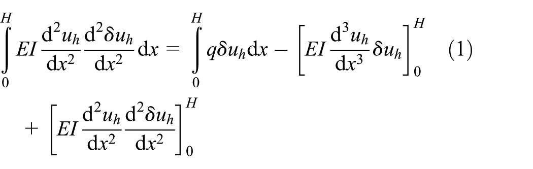
This section discusses the plastic hinge modeling using GFEM shape functions and its characteristics. The classical Euler–Bernoulli beam is utilized for the first-order plastic hinge analysis performed in this study. The weak form of its governing equation is given by
where
where

where
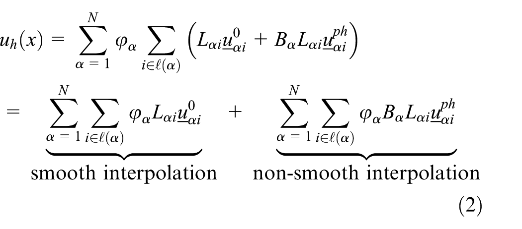
In the lumped plasticity approach, the displacement of the beam is continuous at the location of the plastic hinge, but its derivative is discontinuous, as illustrated in Figure 3. This behavior can be accurately described by the GFEM approximation expressed by equation (2). It consists of both the smooth and non-smooth interpolations. The smooth interpolation can represent the continuous deformation of the beam, while the non-smooth interpolation represents the discontinuity in the derivative of displacement (weak discontinuity) at the plastic hinge location. As can be seen from the second line of equation (2), the former is achieved by the polynomial enrichment functions and latter by the combination of the polynomial and plastic hinge enrichment functions.
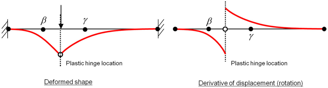
Plastic hinge description based on the lumped plasticity.
Since equation (1) contains the integral term of second derivative of displacement and virtual displacement requiring the C1 feature of shape functions, we use the cubic Hermite shape functions associated with displacement as the partition of unity function


GFEM shape functions for plastic hinge modeling: (a) partition of unity function and (b) enrichment for plastic hinge modeling.
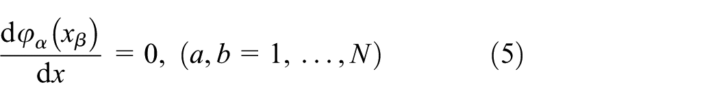
In addition, the derivative of the partition of unity function defined at node α becomes zero at any node β, that is
As the polynomial enrichment functions

where
Figure 4(b) plots the plastic hinge enrichment function (Bα) included in equation (2), which is defined by
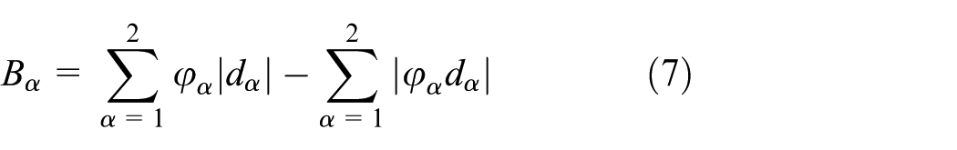
where dα is the distance between the plastic hinge location and node α. Only the nodes of the element having the plastic hinge, which are indicated by β and γ in the figure, are enriched with this special enrichment function. This function was originally proposed and used to describe the weak discontinuity at the bi-material interface by Moës et al., 20 and it can also used for the description of the plastic hinge. This is further discussed in section “Implementation issues.” Notice that it satisfies C1 requirement at the plastic hinge location and C∞ at all the other locations. Furthermore, it can satisfy the following conditions, which can be effectively utilized for straightforward imposition of displacement boundary conditions


It can be also noted that, in general, any GFEM shape functions can be hierarchically added to an existing GFEM discretization as discussed by Duarte et al. 15 For example, in order to create a quartic GFEM approximation, it is possible to add only GFEM shape function terms associated with quartic monomials to the GFEM discretization constructed using linear to cubic GFEM approximations. Due to this feature of the method, the first-order plastic hinge analysis can be efficiently performed with the aid of the static condensation scheme introduced in section “Generalized finite element solution technique based on the static condensation.”
By plugging equations (2) and (3) into equation (1) based on the concept of the Galerkin method, we can obtain

where

and

Here,

where
Implementation issues
This section discusses two issues related to the implementation of the GFEM approximation proposed in section “Generalized finite element discretization for plastic hinge modeling based on lumped plasticity,” which are the imposition of displacement boundary conditions and numerical integration of the proposed GFEM discretization.
Imposition of displacement boundary conditions
Another advantage of the scaled monomials expressed in equation (6) is that the nodal DOFs corresponding to polynomial enrichments with i = 1 and 2 (

This indicates that

Therefore, if
Numerical integration
As in other generalized/extended finite element applications with interfaces,22,23 the numerical integration of elements with the plastic hinge enrichment defined by equation (8) requires the subdivision of integration elements. Figure 5(a) illustrates the numerical integration scheme for two-dimensional elements cut by a crack interface. 23 In this case, the crack is described by Heaviside enrichment function, and the GFEM shape functions with this enrichment satisfy only C0 requirement at the location of crack interface. As a result, the standard integration rule such as Gauss quadrature cannot exactly integrate stiffness components computed with these shape functions if a single integration domain is used for the entire element. For the same reason, the fiber beam element with the plastic hinge enrichment needs to be subdivided at the plastic hinge location, at which only C1 requirement is satisfied, and a numerical integration rule must be applied to each of the subdivided integration elements as illustrated in Figure 5(b). For the numerical integration of the GFEM discretization proposed in this study, the standard Gauss quadrature rule is adopted.

Numerical integration scheme: (a) two-dimensional elements cut by a crack interface and (b) beam element with a plastic hinge enrichment.
Numerical experiments
In this section, the convergence analysis of the example shown in Figure 6 is performed to investigate the effectiveness of the proposed GFEM for the plastic hinge modeling based on the lumped plasticity. This model problem has a plastic hinge at the center of the span and is solved using both the GFEM and standard FEM for comparison purpose. The geometrical configuration of the model problem, material properties and magnitude of the linearly distributed loading are also indicated in the figure. The magnitude q0 is 1.0.

Model problem with an internal hinge at the center of the span subjected to linearly distributed loads.
The exact solution of this model problem (uexact) is expressed by

The exact strain energy of this problem can be calculated using the above exact solution, and is stated as

The relative error of convergence results
where
Case with an even number of elements of equal size
In this section, a uniform h-extension is performed on the model problem using an even number of elements of equal size in the finite element mesh. As a result, the internal hinge is always located at the node of elements, as shown in Figure 7. In the standard FEM analysis, this can be modeled by changing the connectivity of the node represented by a circle in the figure.

Uniform mesh refinement procedure for the standard FEM analysis with an even number of elements.
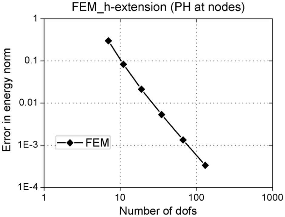
Table 1 presents the convergence analysis results obtained using the standard FEM, where the cubic Hermite shape functions (p = 3) are utilized. The number of elements, number of DOFs, relative error in energy norm, strain energy, and slope in log–log scale (ratio of the relative error in energy norm to the number of DOFs) are listed in the table. The results of the table are plotted in log–log scale in Figure 8 by having the number DOFs as x-axis and the relative error in energy norm as y-axis. As expected, the convergence rate of the standard FEM analysis approaches the theoretical value, 21 which is (p – 1) = 2, with increasing number of DOFs.
Convergence analysis results of h-extension obtained using the standard FEM with an even number of elements.

DOF: degree of freedom.
H-extension performed on the model problem using the standard FEM with an even number of elements.
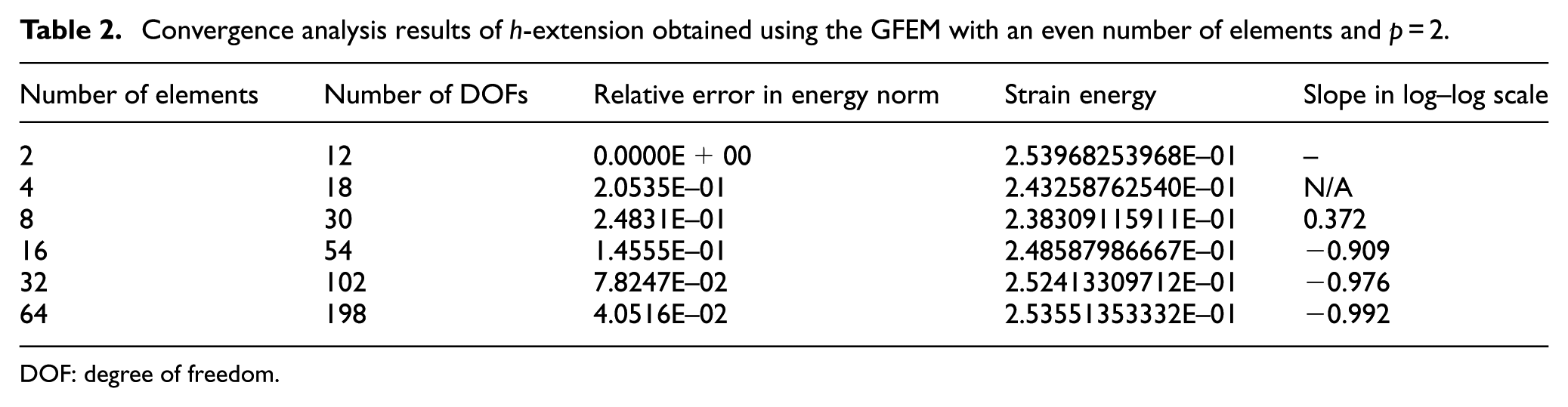
Similarly, the results of uniform h-extension obtained using the GFEM with quadratic, cubic, and quartic polynomial enrichment functions are listed in Tables 2–4, respectively. The uniform mesh refinement procedure of this GFEM convergence analysis is illustrated in Figure 9, and the plastic hinge is modeled by the special enrichment functions given by equation (7), instead of the changing its nodal connectivity as in the standard FEM. The results of Tables 2–4 are plotted in log–log scale in Figure 10.
Convergence analysis results of h-extension obtained using the GFEM with an even number of elements and p = 2.
DOF: degree of freedom.
Convergence analysis results of h-extension obtained using the GFEM with an even number of elements and p = 3.

DOF: degree of freedom.
Convergence analysis results of h-extension obtained using the GFEM with an even number of elements and p = 4.
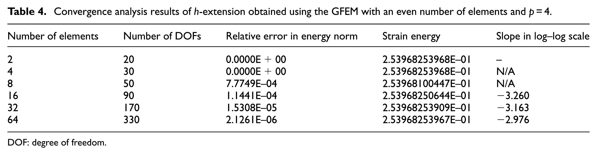
DOF: degree of freedom.

Uniform mesh refinement procedure for the GFEM analysis with an even number of elements.

H-extension performed on the model problem using the GFEM with an even number of elements.
Several interesting observations can be made from these results. First, linear convergence rates are achieved in all of the three cases. The theoretical convergence rate for uniform h-extension of smooth one-dimensional problems is given by (p – 1), where p is the polynomial order of shape functions. The convergence rates of the GFEM results with p = 2, 3, and 4 at the last convergence stage are 0.992, 2.043, and 2.976, respectively. This confirms that the convergence rates of the proposed GFEM analysis results coincide with the theoretical estimates very well, thus demonstrating its effectiveness and accuracy. Second, it can be seen from the results that the GFEM with quartic polynomial enrichments exhibits the lowest level of relative error for a given number of DOFs, thus confirming that it is the most effective one among the three cases discussed. Third, interestingly, the GFEM discretization can exactly approximate the solution of the problem if only two elements are used in the mesh. Similarly, the GFEM discretization with p = 3 or 4 can also produce the exact solution in case that four elements are used. The partition of unity functions in the proposed GFEM are cubic polynomials and thus the GFEM shape functions with high-order polynomial enrichments may be able to locally approximate the solution, of which polynomial order is even higher than that of the enrichment functions used, with high accuracy. Therefore, if only two or four elements are used in the domain, it may be possible to obtain a highly accurate solution using the GFEM shape functions. A similar observation was made by Son et al. 24
Tables 5–7 summarize the results of p-extension performed using the GFEM shape functions with 4, 16, and 64 elements, respectively. The results of the tables are plotted in Figure 11 in log–log scale. These results indicate that exponential convergence rates can be achieved with increasing polynomial order of GFEM shape functions. This result coincides with theoretical estimates as discussed by Belytschko et al., 22 demonstrating the effectiveness and robustness of the proposed GFEM.
Convergence analysis results of p-extension obtained using the GFEM with four elements.

DOF: degree of freedom.
Convergence analysis results of p-extension obtained using the GFEM with 16 elements.

DOF: degree of freedom.
Convergence analysis results of p-extension obtained using the GFEM with 64 elements.
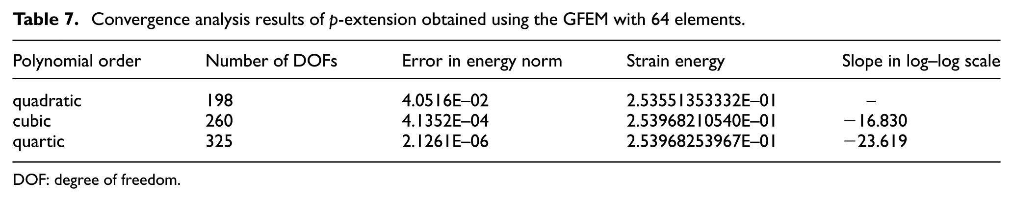
DOF: degree of freedom.

P-extension performed on the model problem using the GFEM with an even number of elements.
Case with an odd number of elements of equal size
In this section, we perform convergence analyses for the model problem with an odd number of elements of equal size. As a result, the internal plastic hinge is always located inside an element, as shown in Figure 12. This case can be handled only using the proposed GFEM discretization, not by the standard FEM. In the GFEM discretization, the nodes of the element with the plastic hinge are enriched with the plastic hinge enrichment function described by equation (7).

Uniform mesh refinement procedure for the GFEM analysis with an odd number of elements.
Tables 8–10 list the results of uniform h-extension obtained using the GFEM with quadratic, cubic, and quartic polynomial enrichment functions. The results of the tables are plotted in log–log scale in Figure 13. Similarly to the convergence analysis results of section “Computational cost analysis,” linear convergence rates are achieved in all of the three cases even though the internal plastic hinge is described by the plastic hinge enrichment function, not by an element node and its connectivity. The convergence rates of the GFEM results with p = 2, 3, and 4 at the last convergence stage are 1.013, 2.085, and 3.104, respectively. This again confirms that the convergence rates of the GFEM analysis results coincide with the theoretical estimates very well, thus demonstrating the effectiveness and accuracy of the proposed GFEM.
Convergence analysis results of h-extension obtained using the GFEM with an odd number of elements and p = 2.

DOF: degree of freedom.
Convergence analysis results of h-extension obtained using the GFEM with an odd number of elements and p = 3.

DOF: degree of freedom.
Convergence analysis results of h-extension obtained using the GFEM with an odd number of elements and p = 4.

DOF: degree of freedom.

H-extension performed on the model problem using the GFEM with an odd number of elements.
Tables 11–13 summarize the results of p-extension performed on the model problem using the GFEM shape functions with 5, 17, and 65 elements, respectively. The results of the tables are plotted in log–log scale in Figure 14. These results indicate that exponential convergence rates can be achieved with increasing polynomial order of GFEM shape functions. This result coincides with theoretical estimates as discussed by Szabo and Babuška, 21 demonstrating the effectiveness and robustness of the proposed GFEM even in the case where the internal plastic hinge is described by the special plastic hinge enrichment function.
Convergence analysis results of p-extension obtained using the GFEM with five elements.

DOF: degree of freedom.
Convergence analysis results of p-extension obtained using the GFEM with 17 elements.
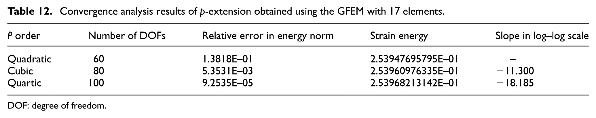
DOF: degree of freedom.
Convergence analysis results of p-extension obtained using the GFEM with 65 elements.

DOF: degree of freedom.

P-extension performed on the model problem using the GFEM with an odd number of elements.
Efficient first-order plastic hinge analysis based on the GFEM
In this section, the first-order plastic hinge analysis based on the proposed GFEM is discussed, and its efficient solution technique based on the static condensation scheme is proposed. The effectiveness of this approach is investigated by analyzing the results of a model problem solved using both of the standard FEM and proposed GFEM.
First-order plastic hinge analysis
The first-order plastic hinge analysis is a series of linear analyses, where a structural collapse is simulated by the successive formation of plastic hinges in frame members. 12 This is one of the simplest types of analyses to simulate the collapse of a building structure, as it does not require the nonlinear iteration procedure, which is generally the most time-consuming part of nonlinear analyses.
In the first-order plastic hinge analysis, if internal bending moment reaches the limit capacity at a certain location, a plastic hinge is formed and its bending resistance is kept constant as the limit value while other plastic hinges develop, as shown in Figure 15. The plastic hinge modeling is based on the lumped plasticity and thus the plastic hinge can be formed by inserting an internal hinge (or pin) at its location. Then, this procedure is repeated until the entire structure becomes unstable. The typical procedure of the first-order plastic hinge analysis is summarized in Figure 16.
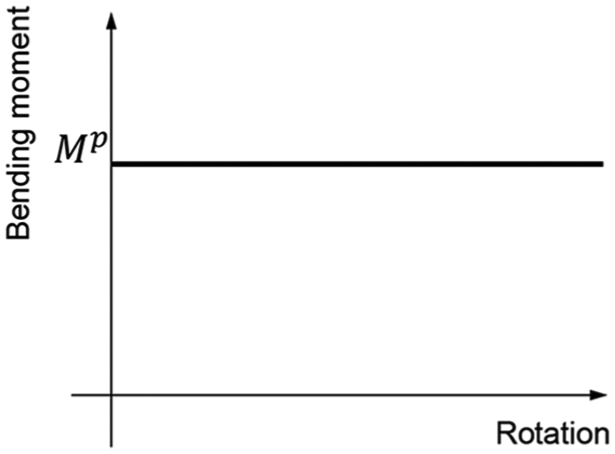
Plastic hinge moment–rotation relation.

Typical procedure of the first-order plastic hinge analysis.
Figure 17 shows an example of the first-order plastic hinge analysis performed on a single-span frame structure using the standard FEM. A linear elastic analysis is performed on this structure in order to find the location of the first plastic hinge, which is formed inside the horizontal frame member (member 3) in this example, as shown in Figure 17(c). In order to describe it, the member 3 needs to be replaced by two frame elements (members 5 and 6), and an internal hinge is inserted at the node between the two new elements (Figure 17(d)). Then, the second linear elastic analysis is performed on the modified structure by applying additional vertical and horizontal loads, and the second plastic hinge is formed at the right end of member 6 (Figure 17(e)). This plastic hinge is located at an elemental node, so it can be modeled by inserting an internal hinge here without adding more elements. With the addition of the second plastic hinge, the structure becomes unstable, and thus the progressive collapse analysis is over.

First-order plastic hinge analysis using the standard FEM: (a) original structure, (b) deformation due to applied forces, (c) formation of the first plastic hinge, (d) insertion of a node at the location of the first plastic hinge, (e) formation of the second plastic hinge, and (f) connectivity change of the node at the location of the second plastic hinge.
From this description of the first-order plastic hinge analysis using the standard FEM, it is clear that the structure has to be modified after the formation of a plastic hinge and reanalyzed from scratch to find the next plastic hinge location, since it requires either the replacement/addition of elements or change in connectivity between elements. In general, a real-world example of frame structural collapses requires the formation of thousands of plastic hinges, and thus its computational cost is enormously high. Consequently, we may need a more efficient methodology that requires less computational cost.
Figure 18 illustrates the first-order plastic hinge analysis performed on the same example as in Figure 17 using the proposed GFEM. The main difference between the two approaches is the description of plastic hinges. In order to describe the first plastic hinge, the proposed GFEM enriches the two nodes of the horizontal element with the special plastic hinge enrichment discussed in section “First-order plastic hinge analysis,” instead of modifying the mesh of the frame structure as in the case of the standard FEM (Figure 18(d)). Similarly, the second plastic hinge can be inserted by enriching only the node at the second plastic hinge location with the plastic hinge enrichment (Figure 18(f)). Apparently, the plastic hinge enrichment of the proposed GFEM requires the addition of more DOFs to the existing GFEM discretization but does not require the modification of the existing FE mesh. This advantage can be greatly amplified with the aid of the solution technique based on the static condensation, which is introduced in detail in the next section.
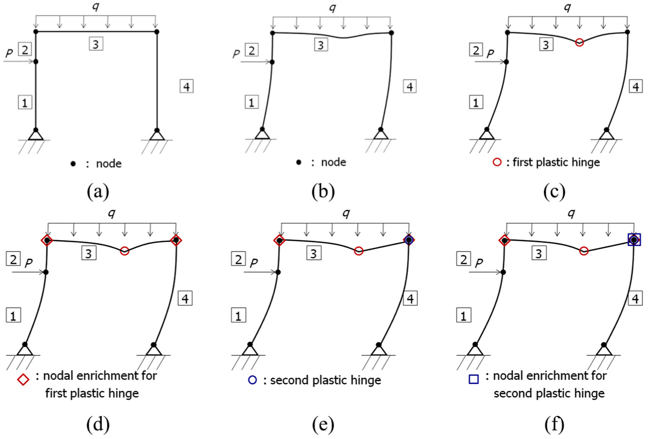
First-order plastic hinge analysis using the proposed GFEM: (a) original structure, (b) deformation due to applied forces, (c) formation of the first plastic hinge, (d) enrichment of the nodes of the element with the first plastic hinge, (e) formation of the first plastic hinge, and (f) enrichment of the node with the second plastic hinge.
Generalized finite element solution technique based on the static condensation
As already discussed in section “Generalized finite element discretization for plastic hinge modeling based on lumped plasticity,” any GFEM shape functions can be hierarchically added to an existing GFEM discretization. This guarantees that in the first-order plastic hinge analysis, the stiffness matrix of the problem at the previous step is always nested in that at the next step because the plastic hinges once added to the structure never disappear. This unique feature enables the application of the static condensation scheme proposed by Gupta et al. 13 in the first-order plastic hinge analysis performed using the GFEM discretization discussed in section “Plastic hinge modeling using the GFEM.”
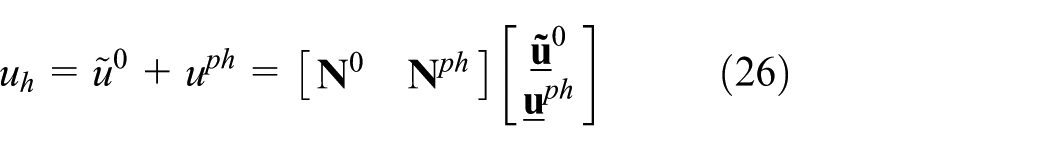
If a plastic hinge is inserted in the frame structure using the proposed GFEM shape functions, the GFEM approximation can be expressed by equation (11). As already discussed in section “Generalized finite element discretization for plastic hinge modeling based on lumped plasticity,” this composition of the GFEM approximation can result in the stiffness matrix form given by

In most of the building structures that are designed and constructed in industry, plastic hinges are generally formed relatively in a small number of frame elements at the final stage of structural failure in comparison with the total number of elements, as can be seen in the example of Figure 2. Consequently, in the first-order plastic hinge analysis based on the proposed GFEM, the number of DOFs associated with plastic hinge enrichments (p) is much smaller than that associated with polynomial enrichments (n). This condition can be stated as

Therefore, if the factorized form of
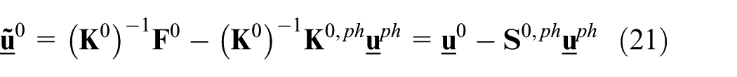
where

If the factorized form of

Then, the terms

This can be rewritten as
The dimensions of matrices
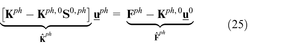
In the procedure described up to this point, most of the computational cost is spent in the computations stated by equations (22) and (25). This is further discussed in the next section.
Numerical experiments
This section investigates the effectiveness of the GFEM solution technique discussed in section “Generalized finite element solution technique based on the static condensation” by solving a model problem illustrated in Figure 19 using both the standard FEM and proposed GFEM and by comparing their computational costs. The model problem shown in the figure is basically a multi-span continuous beam, of which spans have a constant length (L) and bending stiffness (EI). Its spans can be categorized into two types such as those with and without concentrated loads. The spans with a single concentrated load (P) represent the frame members with plastic hinges, while the free spans represent those without plastic hinges. The number of the concentrated loads in the continuous beam is denoted by nA, and the number of the free spans is denoted by nB. The limit bending capacity for plastic hinge formation is set to be the plastic bending moment. All of the blue and orange elements in Figure 19 have the same plastic bending moments, respectively, and the plastic bending moment of the former

Model problem for the cost analysis of the proposed GFEM.
In order to avoid the simultaneous formation of many plastic hinges, the frame members with orange color have ten times greater plastic moment than those with blue color. Under this condition, (2nA – 1) plastic hinges are formed in the structure before it becomes completely unstable. The progressive collapse procedure of this structure with nA = 5 is illustrated in Figure 20, and the plastic hinges are represented by red solid circles. In this case, nine plastic hinges are formed in the structure before its collapse, as indicated in the figure.
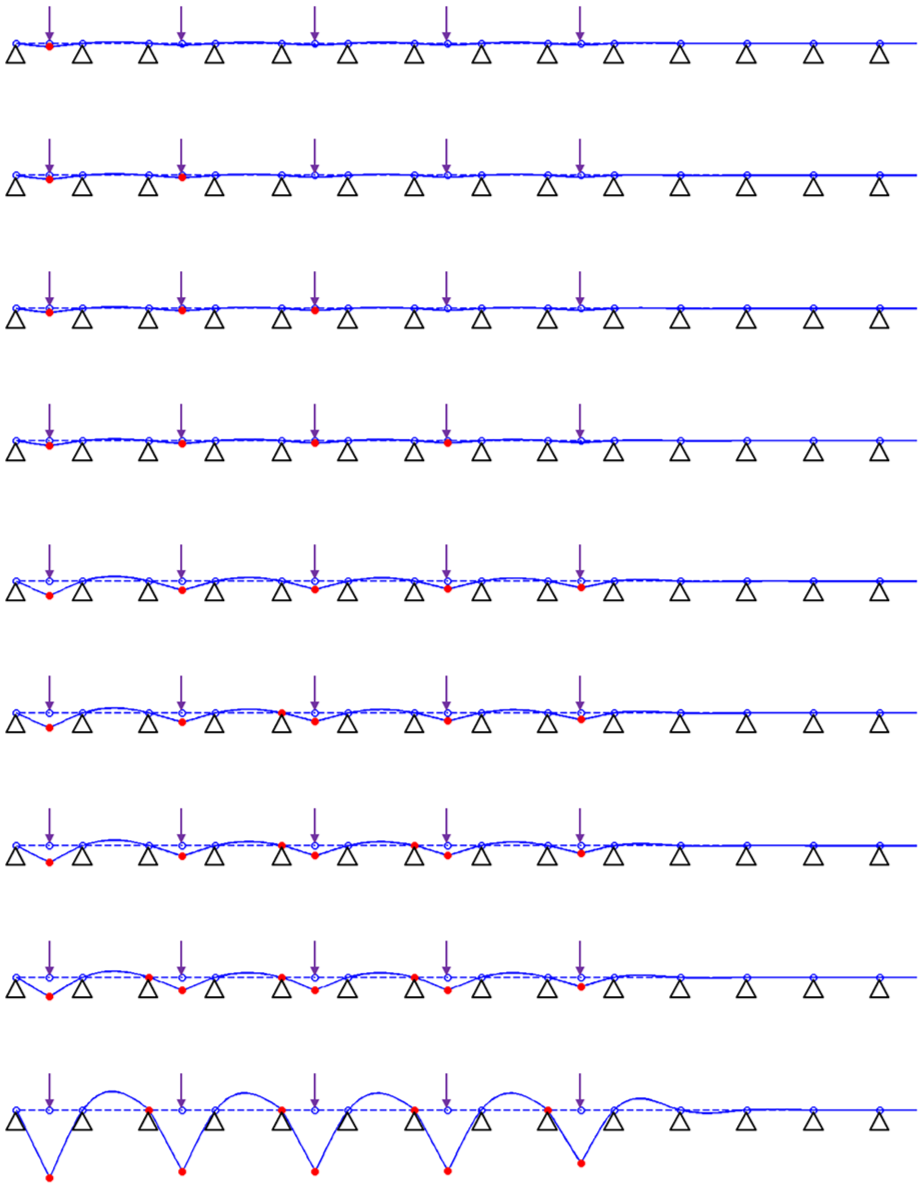
Progressive collapse mechanisms of the model problem.
Computational cost analysis
In this section, the computational costs required to perform the first-order plastic hinge analysis of the model problem using the standard FEM and proposed GFEM are defined in terms of an accumulated CPU time, respectively, and their computational costs are compared. If its first-order plastic hinge analysis is performed using the standard FEM, a direct solver such as Cholesky factorization needs to be used at all steps. As a result, its accumulated CPU time required to perform the analysis up to step (2nA – 1) (TFEM) can be estimated by the following equation

where
In the proposed GFEM plastic hinge analysis, the direct solver is used only at the first step, and the solutions at subsequent steps can be obtained using the static condensation scheme discussed in section “Generalized finite element solution technique based on the static condensation.” In the procedure of the static condensation, most of the computational cost is spent during the computations expressed by equations (22) and (25), as already mentioned in section “Generalized finite element solution technique based on the static condensation.” Therefore, the accumulated CPU time required by the GFEM analysis up to step (2nA – 1) (TGFEM) can be estimated as

where
The first-order plastic hinge analyses of the model problem are performed under three different conditions such as nB = 800, nB = 1600 and nB = 3200 using both the standard FEM and proposed GFEM with cubic polynomial enrichments. Here, in all of the three cases, nA is constantly equal to 5, as in the case shown in Figure 19. The number of DOFs of the standard FEM and proposed GFEM approximations at the first step are summarized in Table 14. This table indicates that the GFEM approximation requires twice more the DOFs than the standard FEM approximation. As can be seen from equation (4), the cubic GFEM shape functions require four DOFs per node, while the cubic Hermite shape functions of the standard FEM requires only two.
Number of DOFs required by the standard FEM and GFEM approximations at the first step.

FEM: finite element method; GFEM: generalized finite element method.
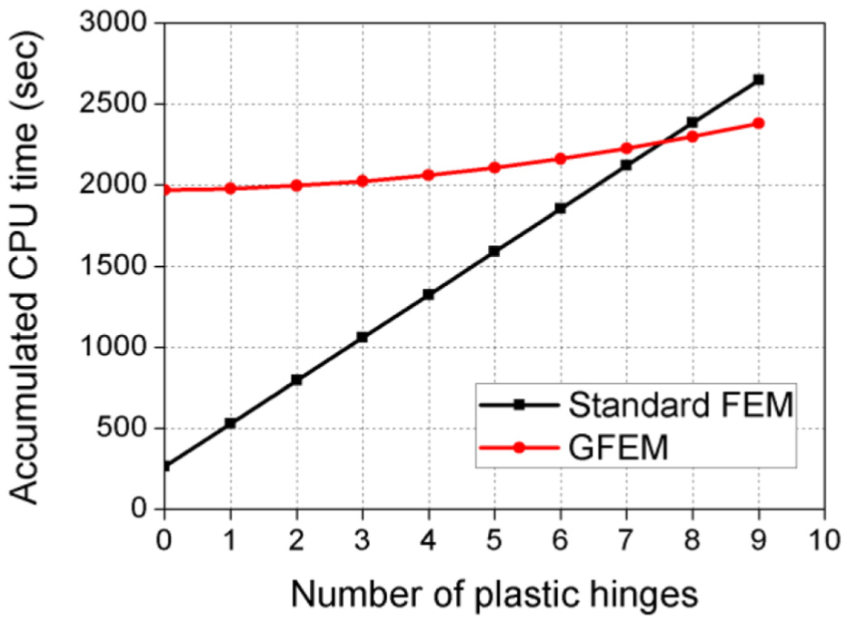
The computational costs of the standard FEM and proposed GFEM analyses for the three cases are plotted in Figures 21–23, respectively. Several interesting observations can be made from these results. First, in the standard FEM analysis, the accumulated CPU time increases in proportion with the number of plastic hinges formed in the structure. In contrast, the GFEM analysis requires a relatively high amount of CPU time to obtain the first step solution, but from the second step, the required CPU time becomes much less and gradually increases as the number of plastic hinges increases. This confirms that the static condensation scheme proposed in section “Generalized finite element solution technique based on the static condensation” can greatly reduce the computational cost to obtain the solutions after the first step. As a consequence, the accumulated CPU time required for the GFEM analysis becomes smaller than that of the standard FEM analysis if a sufficient number of plastic hinges are formed in the structure before its collapse.

Computational costs of the standard FEM and GFEM analyses for nB = 800.

Computational costs of the standard FEM and GFEM analyses for nB = 1600.
Computational costs of the standard FEM and GFEM analyses for nB = 3200.
Second, the cost effectiveness of the proposed GFEM becomes better if the size of the problem increases. For example, it can be seen from Figure 21 that the accumulated CPU time required by the GFEM analysis is larger than that by the standard FEM analysis, but the computational cost of the GFEM analysis becomes smaller than that of the standard FEM when the number of plastic hinges is more than eight in Figures 22 and 23.
Third, in the number of plastic hinges versus the accumulated CPU time graph shown in Figures 21–23, the slope of the GFEM analysis gradually increases as the number of steps increases. This happens mainly because the static condensation scheme proposed in section “Generalized finite element solution technique based on the static condensation” may not be computationally effective if the condition stated by equation (20) is not fully satisfied. In other words, it becomes less effective with increasing number of plastic hinges. In order to address this issue, the alternating scheme of direct solution and static condensation is proposed in the next section.
Alternating scheme of direct solution and static condensation
Figure 24 illustrates the alternating scheme of direct solution and static condensation in order to alleviate the effectiveness degradation of the static condensation scheme with increasing number of plastic hinges formed in the structure. It can be seen from the comparison of equations (27) and (28) that the static condensation scheme may require more CPU time than the direct solver if

Alternating scheme of direct solution and static condensation.
As an example to demonstrate the effectiveness of the proposed alternating scheme, the model problem of a larger size is solved for nA = 50 and nB = 3200 using both the standard FEM and GFEM with the alternating scheme. In this case, a total of 99 plastic hinges are formed before the collapse of the structure. The number of DOFs at the first step required by the standard FEM and GFEM are 6550 and 13,100, respectively. The computational costs of the two methods are plotted in Figure 25. It can be noted from the figure that the accumulated CPU time of the GFEM approach is greatly reduced with the aid of the alternating scheme, and the difference between the costs of two methods becomes more significant as the number of plastic hinges formed in the structure increases. This confirms that the proposed alternating scheme is highly effective to enhance the solution technique based on static condensation.

Cost reduction of the GFEM analyses performed with the proposed alternating scheme for nA = 50 and nB = 3200.
Conclusion
In this study, we proposed a generalized finite element formulation for plastic hinge modeling based on lumped plasticity in the classical Euler–Bernoulli beam. In this approach, the plastic hinges are modeled using a special enrichment function, which can describe the weak discontinuity of the solution at the location of the plastic hinge. Furthermore, it is also possible to insert a plastic hinge at an arbitrary location of the element without modifying its connectivity or adding more elements. Instead, the formations of the plastic hinges are achieved by hierarchically adding more DOFs to existing elements. Due to these features, the proposed methodology can efficiently perform the first-order plastic hinge analysis of large-frame structures. A generalized finite element solution technique based on the static condensation scheme was also proposed in order to reduce the computational cost of a series of linear elastic problems, which is in general the most time-consuming portion of the first-order plastic hinge analysis. The main conclusions of this study can be summarized as follows:
The proposed GFEM is able to achieve the theoretical convergence rates of the static analysis, which are in principle identical to those of the standard FEM, for various polynomial orders of its shape functions such as quadratic, cubic, and quartic orders in both cases, where plastic hinges are located at nodes and within an element.
The GFEM approximations with high-order polynomial enrichments such as p = 4 are effective in achieving the low level of relative error in energy norm for a given number of DOFs.
The GFEM shape functions with high-order polynomial enrichments are able to obtain an almost exact solution if only one or two elements are used in the domain. This seems possible because the partition of unity functions used in this approach are the cubic Hermite shape functions associated with displacement, and the GFEM shape functions with high-order polynomial enrichments may be able to locally approximate the solution, of which polynomial order is even higher than that of the enrichment functions used.
The solution technique based on the static condensation is able to significantly reduce the computational cost of the first-order plastic hinge analysis using the GFEM approximation proposed in this study. Its effectiveness is especially high when the size of the problem is very large than the total number of plastic hinges formed in the structure before its collapse.
The alternating scheme of direct solution and static condensation is able to prevent the effectiveness degradation of the static condensation that may occur if the number of plastic hinges formed in the structure increases.
Footnotes
Handling Editor: Wen-Hsiang Hsieh
Declaration of conflicting interests
The author(s) declared no potential conflicts of interest with respect to the research, authorship, and/or publication of this article.
Funding
The author(s) disclosed receipt of the following financial support for the research, authorship, and/or publication of this article: This work was supported by a National Research Foundation of Korea (NRF) grant funded by the Korean government (Ministry of Science, ICT & Future Planning) (grant no.: 2017R1A2B4004729).