
Abstract
A technique for controlling the noise radiation of folded plate structures is developed in this article. In this technique, the topography optimization method is introduced and an artificial parameter called
Keywords
Introduction
Analytical solutions of the governing differential equations in acoustics can only be obtained on the condition that the physical boundaries are simply described in mathematical terms as in Meirovitch. 1 This is one of the rare cases in engineering. Therefore, it is generally necessary to employ approximate numerical methods. The two most widely used methods are the finite element method (FEM) and the boundary element method (BEM). 2 The application of BEM to acoustics is described, and an overview of the literature is given in the book by Ciskowski and Brebbia. 3 Once the FEM had been given a firmly mathematical foundation, it can be effectively used to analyze other physical problems represented by partial differential equations. The field of acoustics has taken no exception. The BEM was developed to predict the noise radiated from vibrating structures which are immersed in an infinite acoustic medium.4,5 Vibro-acoustic problems can be analyzed by combining the equations of motion of the vibrating structure, obtained using finite element techniques, with the equations of motion of the acoustic medium, obtained using either FEM or BEM. 6
Infinite- or semi-infinite-domain problems usually occur in the modeling of smart structures. Interaction of fields with complex geometries in conjunction with infinite or semi-infinite domains is modeled by introducing a mathematical boundary within which the finite element representation is employed.7,8 On the mathematical boundary, the finite element representation is matched with analytical representations in the infinite or semi-infinite domain. The matching has been done with and without slope constraints on the boundary. Drilling degrees of freedom at each of the nodes of the finite element model are introduced to reduce artificial reflection at the mathematical boundary. 9
In order to control the radiated sound pressure from vibrating structures, the minimization of the velocity on radiating surface is usually taken as the design goal by noise, vibration, and harshness (NVH) engineers. But the velocity on radiating surface cannot be directly selected as objective function.
10
It is noted that the surface velocity is a vector associated with the nodes on the surface and a function of frequency. However, objective function is a single value, making the surface velocity impossible to be used as an objective function directly.11,12 This is a bottleneck when using optimization in NVH computer-aided engineering (CAE). Analysis of sound radiation can use many methods; Fu et al.13,14 present Burton–Miller-type singular boundary method for acoustic radiation analysis, where the singular boundary method is the improvement formulation of BEM. However, it is worth noting that the mathematical theoretical analysis of the present singular boundary method is still incomplete. In this article, a technique for controlling the noise radiation of folded plate structures is developed. An artificial parameter
BEM theory for the exterior acoustic problem
Governing equation and boundary conditions
Consider a vibrating structure
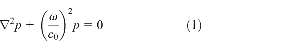
and the Sommerfeld radiation condition as

where

where

Radiation from a vibrating surface.
If

where pressure field
Artificial conditions of boundary
An approximate solution to theory solution is to enclose the vibrating surface

where
If the radius of the sphere
Theory of infinite element
An alternative approach to truncate the unbounded domain
In one dimension, with coordinate
with n = 3 and

where

where

As shown in Figure 2, this transformation maps a polynomial of the form

into one of the forms


One-dimensional infinite element mapping.
In the above equation, the weight functions were taken to be like the pressure functions. This results in the system matrices being symmetric. However, the integrands in these matrices involve complex exponentials, and so special numerical integration techniques have to be used. One of the advantages of these elements is that the more the terms in expression (11) are included, the more deeply the infinite elements can be intruded into the near field without loss of accuracy, and the meshes of the conventional finite element can be reduced.
Another class of elements proposed is referred as conjugated elements. These are the elements which are large but finite in size. The pressure functions were taken as the following form

and the weight function is the complex conjugation of this, that is

This choice takes the harmonic spatial variation from the integrals involved in the calculation of the system matrices. In this case, the weight functions were taken to be

The factor
BEM
The BEM was used as an alternative numerical method to solve the wave equation for quantification of the radiation (or scattering) of an acoustic field by surface. The formulation for the BEM is not derived from the differential wave equation; it is based on a surface integral equation. Initially, the solution for the acoustic pressure is required only on the bounding surface of the acoustic volume. Since the formulation contains only the parameters on the boundary, the elements used in the discretization need only to describe the geometry, pressure, and boundary conditions on radiation surface. With respect to radiation problems, the element mesh is finite, thus avoiding the problem encountered in the conventional FEM. Here is the derivation of the simplest formulation of the BEM, namely, the “direct method,” which was described for the exterior domain cases in section “Direct methods for structure.”
A major problem in the application of the boundary element formulations for exterior problems is the method of overcoming the mathematical difficulty that the solution is not uniquely defined at certain frequencies. The way to overcome the difficulty, which is different from each formulation, is a matter to control the model by the user in addition to the element size considerations.
Direct methods for structure
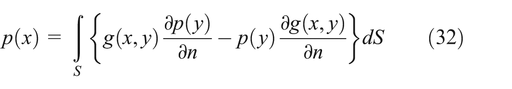
Both the FEM and the BEM are used to solve the acoustic wave equation. In the frequency domain, the wave equation is reduced to the Helmholtz differential equation. The starting point of the BEM is the integral representation of the wave equation. This is known as the Kirchhoff–Helmholtz integral equation (K-HIE). For a volume V enclosed by the surface
where g(x, y) is Green’s function

Definition of the domain for the direct boundary element formulation with the unit normal vector pointing out of the domain.
For two-dimensional problems, Green’s function for the K-HIE is
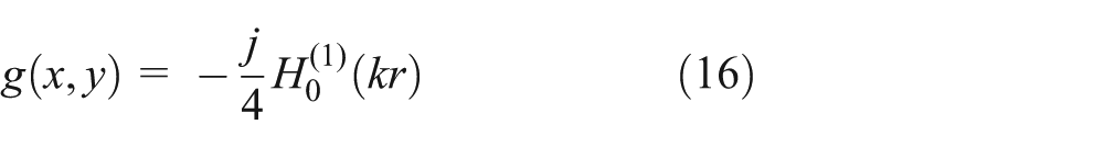
where

In both expressions,
Boundary integral equation
The first main step in deriving the boundary element formulation is to move the point

The
Noting that

where
Boundary element discretization
The surface is now represented by an assemblage of elements similar to those used in the FEM. For the BEM, however, only one-dimensional elements are required for the analysis of a two-dimensional domain, that is, they only have to represent a segment of the boundary represented by a line. For the analysis of a three-dimensional domain, two-dimensional elements are used to represent “patches” of the surface.
Within each element, assume that

and
where, as before,
When these expressions are substituted into the surface integral equation, and it is evaluated for the point

where

and

where the vector

The resulting integral is evaluated using Gauss–Legendre quadrature in

where the two vectors
By allowing the node

where
Each part of the boundary is represented by the nodal values in either

Where the velocity is specified over the whole surface and the solution is required for the pressure, then

and

where
Calculation of internal pressures
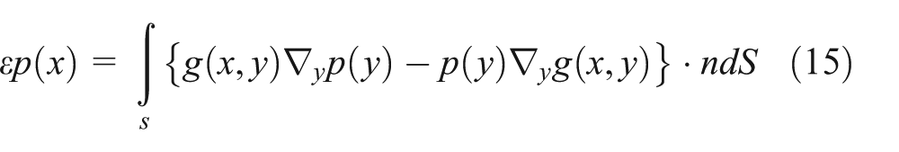
From the solution equation (29), added to the prescribed boundary conditions, the set of normal velocities and pressures at the nodes of the surface can be obtained. Equation (15) was used to evaluate the acoustic pressure at any point in the field points. For a field point
Since
In discretized form

where
and

The Gauss–Legendre quadrature method used for nonsingular elements is used for evaluating expressions (34) and (35). Field point pressures are to be evaluated close to the boundary. The surface mesh should locally contain small elements.
Combining the expressions for several field points gives

where
Radiation and scattering
The boundary element formulation can be used for the solution of radiation problems. If the domain
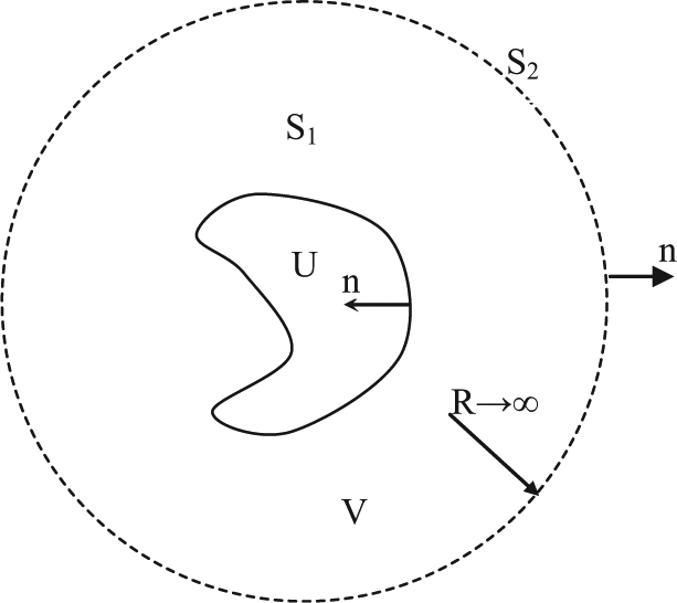
Radiation from a vibrating surface.
Any physical acoustic field arising from a source of finite extent radiates a field which behaves like that of a point source at very large distances (
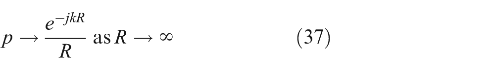
This is a statement of the Sommerfeld radiation condition. It can be shown as

That is, the outer part of the surface that has been taken to infinity contributes nothing to the integral, and therefore, the surface
Topography optimization analysis
Topography optimization
The most economical approach of reducing noise is to structurally minimize the capability of sound radiation in the early design stage. Design optimization is seen as the best analytical tool for this study. The primary factors considered in design optimization are design variables, objective function, and constraints as follows


The difference in design variables forms various kinds of design optimization, for example, size, shape, and topology, topography, and topometry optimization. Topography optimization was used in this study to minimize the sound radiation. Topography optimization divides the design region into smaller areas, each with its own shape variables. The solver of the optimization software performs this process automatically using the parameters defined by the user.
The selection of the nodes to move is automatic. As shown in Figure 5, the new positions of the nodes and elements are determined through the parameters selected by the designer as minimum width (m), draw angle (β), draw height (h), and manufacturing constraints. The process of topography optimization is to move nodes in the direction of the normal vector of an element. The topography optimization had been done iteratively and automatically until the convergence conditions were met.

Scheme of topography optimization using the element normal vectors.
method
The goal of noise reduction is to minimize the sound radiation. In practice, due to the limitation of commercial solvers, dynamic response is only displacement, velocity, or acceleration, instead of sound pressure. Therefore, sound radiation cannot be directly selected as the objective function. Hence, one has to aim to reduce the velocity of radiating surface that plays the role of dynamic load in acoustic analysis. The surface velocity is a vector associated with the nodes on the surface and a function of frequency. However, the response selected as the objective function permits a single value only, which makes the surface velocity impossible to be used directly as an objective function. An artificial parameter, called


where
Numerical example
Steps of the application of the software packages
The steps of the application of the software packages are as follows:
Set up models; generate mesh elements; and set up the calculation conditions (according to the theory of finite element and boundary element) for the folded plate structure, the air hemisphere, and the boundary hemisphere model by software HyperMesh 10. The folded plate structure will also be conducted to optimize topography by software HyperMesh 10.
Run software MSC Nastran to perform the calculations of the displacement parameters and the eigenvalues according to the models set up in step 1.
Based on the models of step 1 and the results calculated in step 2. Use software Sysnoise to perform incorporate calculations among the folded plate structures, the air hemisphere model, and the boundary hemisphere model based on the theory of coupled direct BEM and infinite element method.
The calculation data of step 3 will be linked to software MATLAB to calculate and plot the sound pressure.
Numerical example
A car body structure consists of metal plates. The frame structure and the form channel structure can be modeled as the folded plate. The folded plate is a symmetry structure with crank angle α as shown in Figure 6. The length of the folded plate is 0.3 m, the width is 0.2 m, and the thickness is 0.001 m. The density of this folded plate structure is 7800 kg/m3, and Poisson’s ratio of the folded plate structure is 0.3. The acoustic velocity of the air is 343 m/s, and the air density is 1.21 kg/m3. After optimization, the above structural model is changed from a plate to a shell.

Finite element model of the folded plate structure.
The plate is divided by the four-node quadrilateral shell elements. The finite element model of the folded plate consists of 2400 elements and 2500 nodes. Four external harmonic exciting forces (F1, F2, F3, and F4) are imposed at the four arbitrary nodes in folded plate structure. This article has selected four arbitrary nodes on the folded plate structures, namely, the nodes 21328, 21307, 21256, and 21239. The four arbitrary nodes were used in all calculations before and after optimization. The values of external harmonic exciting forces only affect the calculation results linearly. The analysis frequency range is 15–300 Hz; that is, the acoustic frequency band mainly exists inside the car. All edges of the plate are clamped (200 nodes).
Topography optimization method has been applied to the folded plate model, with different folding angles α are considered. Each folding angle α represents a model shape. In order to obtain a practically optimal shape, some geometrical and topographical constraints are required in optimization. In this optimization, the geometric parameters to control the shape of beads, namely, the drawn height (h), the minimum width (m), and the drawn angle (β) will be specified. The drawn bead height (h) is specified as 5 mm according to the material characteristics of steel plate structures. The minimum drawn bead width (m) is 10 mm according to the size of the plate structure. The drawn angle (β) is defined as 15° according to the actual drawn angle in forging process. In this article, the angle α is chosen with three special values of 30°, 60°, and 90°. The change in α angle leads to variation in the geometry of structure and normal velocity vector of element. The changes will cause the eigenfrequencies, the eigenmodes of plate structure, and the number of iteration to alter in the process of topography optimization. The results after optimization are shown in Figure 7.

Topography model of the folded plate after optimization with folding angles α = 30°, 60°, and 90°.
The optimization software Altair OptiStruct based on the
An acoustic BEM model is also created for the acoustic analysis, as shown in Figure 8. Basing field points were created using Sysnoise. Figure 8 shows the based field point model. All of the acoustic analysis performed was based on the infinite element and direct BEM.

Infinite element model in direct boundary element method.
Subsequently, an acoustic analysis based on the infinite element and direct BEM was carried out; the sound pressure for

Fringe of the sound pressure of the semi-sphere surface (α = 60°).
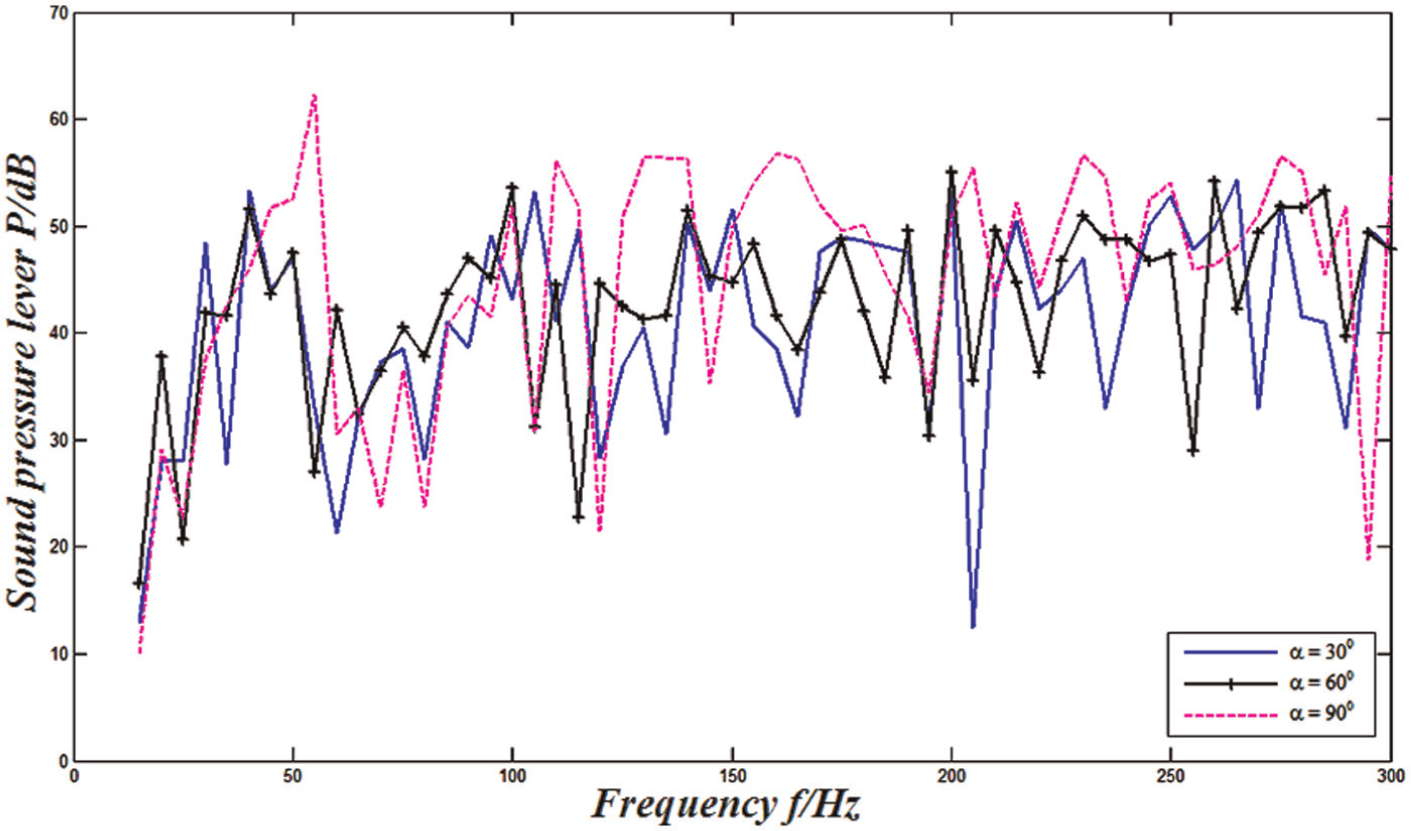
The folded plate structure with folding angles is related to the location of points on the structure surface according to Green’s function (17). When the folding angles α are changed, the initial value of the sound pressure on plate is also changed as shown in Figure 10. However, the average value of the sound pressure on the initial folded plate structure with different folding angles was changed not more than ±1 dB.

Comparison the initial sound pressure of the folded plate with different α angles.
For the direct BEM, the sound pressure, normal velocity, or surface impedance should be identified for each node. The normal velocity on the boundary is often obtained from a structural finite element analysis. The frequency response was input into the BEM software Sysnoise as the normal velocity boundary condition. It is likely that the nodes in the FEM and BEM models are not coincident with one another. However, the BEM software Sysnoise can interpolate the results from the finite element mesh onto the boundary element mesh. The sound pressures at arbitrary node 32128 on the semi-sphere surface in all calculations before and after optimization are shown in Figures 11–13. The sound pressure results computed using the direct BEM with folding angles α = 30°, 60°, and 90° have lower sound pressure after optimization compared with the models before optimization.

Sound pressure before and after optimization for folding angle α = 30°.

Sound pressure before and after optimization for folding angle α = 60°.

Sound pressure before and after optimization for folding angle α = 90°.
It can be seen from Figure 14 that the structural sound pressure of the optimized plates is different when α has different values. This difference helps the designer to select the optimal folding angle α in the early stage of design. The above results of infinite element analysis have shown that the structural sound pressure of folded plate structures can be reduced using topography optimization method. It is shown in this study that the average value of the sound pressure of folded plate before and after optimization has been decreased to approximately 8.9 dB with α = 30°, 6.3 dB with α = 60°, and 3.8 dB with α = 90°.
Sound pressure of optimized folded plates under different folding angles α.
Conclusion
A new technique for reducing structural sound pressure has been developed in this study, in which the topography optimization method is adopted in conjunction with the
Footnotes
Academic Editor: Yunn-Lin Hwang
Declaration of conflicting interests
The authors declare that there is no conflict of interest.
Funding
This work was supported by The Independent Research Project of State Key Laboratory of Advanced Design and Manufacturing for Vehicle Body (grant no. 60870002).