
Abstract
This article proposes a parallel kinematic solar tracker designed for driving high-concentration photovoltaic modules. This kind of module produces energy only if they are oriented with misalignment errors lower than 0.4°. Generally, a parallel kinematic structure provides high stiffness and precision in positioning, so these features make this mechanism fit for the purpose. This article describes the work carried out to design a suitable parallel machine: an already existing architecture was chosen, and the geometrical parameters of the system were defined in order to obtain a workspace consistent with the requirements for sun tracking. Besides, an analysis of the singularities of the system was carried out. The method used for the singularity analysis revealed the existence of singularities which had not been previously identified for this kind of mechanism. From the analysis of the mechanism developed, very low nominal energy consumption and elevated stiffness were found. A small-scale prototype of the system was constructed for the first time. A control algorithm was also developed, implemented, and tested. Finally, experimental tests were carried out in order to verify the capability of the system of ensuring precise pointing. The tests have been considered passed as the system showed an orientation error lower than 0.4° during sun tracking.
Introduction
Grid parity is a major issue in renewable energy systems (RES); it occurs when electricity generated by an alternative energy source is cheaper than purchasing power from the electricity grid. In order to reach grid parity, it is necessary to reduce the cost of energy production and to guarantee a high efficiency of the overall system. In photovoltaics, the degree of use and conversion of solar radiation directly affect the overall system efficiency. The quantity of exposed surface of the system and the comparison of the output energy produced with the input energy absorbed are the main elements to analyze. In Chin et al. 1 for instance, a single-axis smart sun tracker is developed to better direct the photovoltaic panels toward the sun in order to significantly increase the amount of energy produced. Concentrating the sunlight onto a very small high-efficiency solar cell2–4 allows decreasing the influence of the cost of the solar cell on the cost of the total system 5 and a better rational use of the site of installation. Moreover, considering the same amount of output power, a concentrated system occupies less soil than a traditional one. The concentration ratio 6 is a key factor in concentration photovoltaic (CPV) systems, and it has to be maximized in order to reach grid parity and higher efficiency. The precision requirement in the relative alignment between the sun and the system increases with the concentration ratio, as the acceptance angle of the system strongly decreases with this parameter. In high-concentration photovoltaic (HCPV) systems, the maximum allowed pointing error can decrease to 0.4°.
Among the trackers that are originally made to drive flat modules, only the ones that are characterized by a high precision in solar pointing and a high stiffness are suitable for the exploitation of the concentrator modules. In Roth et al., 7 a powerful 2-degree-of-freedom (DOF) controlled architecture for sun tracking is illustrated. In Mousazadeh et al., 8 a survey of the possible mechanism layouts for sun tracking is presented. This work shows that the most efficient device is the azimuth/elevation type: in Itul and Pisla 9 and Kulkarni et al., 10 it is possible to find two examples of this type of device. Alignment errors are generally more effective on the energy production of concentrator modules. A misalignment larger than the acceptance angle causes a stop in energy production, whereas for a flat module it only causes a reduction in the power output. For that reason, the design of an efficient control system also seems to be important for maximum exploitation of an HCPV system. 11
In the field of robotics, high stiffness requirements can often be addressed by adopting a parallel kinematic architecture. 12 This kind of mechanism is characterized by lower deflections of the limbs since the load is split between more links with respect to serial manipulators.
Many studies have dealt with the characterization of stiffness for parallel mechanisms in different applications.13–15 The application of a suitable control technique makes it possible to obtain even higher precision. 16
In particular, in the field of sun tracking, several different parallel mechanism layouts were proposed. A relevant example is provided in Cammarata. 17 In Alexandru and Pozna, 18 a two-axis solar tracker is deeply analyzed from the point of view of the dynamic deformation of the components of the mechanism under the force exerted by the wind. Some data about energy consumption for tracking are also reported. A high stiffness of the mechanism is gained through the usage of self-locking worm drives to actuate the joints. In Altuzarra et al., 19 the sun tracking is pursued with a redundant 4-DOF parallel manipulator to reduce energy consumption. The kinematic design is presented, but no results are shown about the effective amount of absorbed energy. Besides, no results are presented regarding the stiffness of the manipulator. Moreover, it seems that a prototype has never been built.
As can be deduced by the state of the art,20,21 parallel kinematic machines also show several disadvantages: their workspace is generally limited, and in some cases, it can be further limited by singularities. Moreover, the input–output relationship is generally highly nonlinear, making the control of the mechanism a delicate issue. The principal purpose of this article is then to completely develop a relevant example of a controlled parallel kinematic machine for sun tracking, trying to exploit the advantages of this kind of mechanism and limiting at the same time their well-known flaws.
This article describes the design process and the results obtained in the development of a solar tracker designed according to the layout proposed by Dunlop and Jones 22 and known as “the Canterbury tracker,” consisting in a 3 RSR/US robot. This mechanism was originally devised for the purpose of night sky observation. Dunlop and Jones studied the kinematic properties of the mechanism from a theoretical point of view, and they extended their kinematic studies only to input/output singularities of the manipulator.
In this article, an analysis of the constraint singularities is also presented as a function of the different lengths of the links of the mechanism. Furthermore, the realization of a small-scale prototype and the tests performed to validate the suitability of the mechanism for sun tracking are described.
The first part of this work focuses on the problem of finding a geometrical configuration suitable to satisfy the workspace requirements to allow sun tracking in any season or latitude. The reachable configurations with different geometrical proportions are computed and singularities are analyzed. In this section, forward and inverse kinematics are also described.
The second part of this work deals with the construction of a small-scale prototype, its sensitization, and control in order to use the machine as a sun tracker. The developed control method uses an orientation sensor which was presented in Zeroual et al., 23 while the control logic was specifically developed to deal with a parallel kinematic machine. Finally, the results of some tests carried out outdoors are presented and discussed.
Description of the structure
The mechanism driving the photovoltaic modules is presented herein and it is designed according to the schematics of Figure 1. It is a 2-DOF structure composed by two platforms linked by four limbs. Three of them are equal, and each one counts two identical bars (1) connected by a spherical joint (2) and attached to the fixed platform (3) and to the moving platform (4) by revolute joints (5). The hinges are located at the midpoints of the sides of two identical equilateral triangles, representing the platforms. The fourth limb (6) is fixed in the intersection of the bisectors of the angles of the same triangles.

Parallel kinematic solar tracker: definition of the structure.
The fourth limb, here called pointer strut, is attached to the center of both the fixed platform and the moving platform, respectively, by a spherical joint (7) and a universal joint (8). This inner limb is added in order to block the DOF along the vertical axis, keeping the centers of the two platforms always at the same distance one from another.
Photovoltaic modules are fastened to the moving platform. The azimuth and elevation angles are controlled by actuating two limbs (9, 10) while the third one is passive (11); the actuation elements are applied to the lower arms attached to the fixed platform.
Figure 2 shows the actuated angles β1 and β2; the azimuth (α) and elevation (ζ) angles define the orientation of the moving platform. The angles β1 and β2 are actuated through two stepper motors, to which a series of gear trains are linked to increase the output actuation torques. Each gear train is a self-locking worm drive. This means that the stiffness parameters associated with the actuated joints depend only on the warpage of the teeth under stress. The diagonal matrix composed by these stiffness constants is shown in the following equation:


Solar angles related to the solar tracker and Cartesian coordinate systems.
The values of the stiffness constants are evaluated from the information contained in datasheet of the worm drives. Any movement of the mechanism can be regarded, with a very good approximation, as a time sequence of static postures. This holds due to the nature of the stepper motors and the slowness of the motion. Indeed, during a minute the actuated angles have a nominal value variation that is equal to one-thousandth of a radiant as order of magnitude. For that reason, an analysis of the dynamics of the system becomes almost meaningless. On the contrary, a static stiffness analysis is useful to understand the order of magnitude of the external actions needed to provide unwanted displacements of the structure.
Forward kinematics
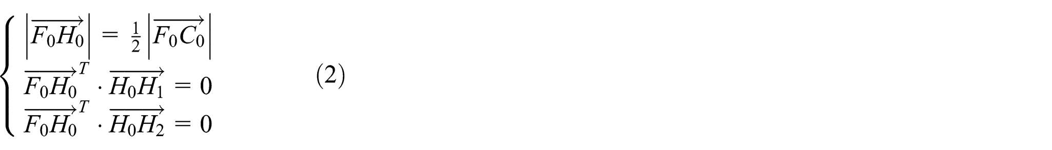
The objective of this analysis is to define, for each configuration of the structure, where the photovoltaic panel is positioned subsequently to a command from the actuation system. Starting from the knowledge of the actuated angle, it is possible to solve a system of three equations (equation (2)) for determining the orientation of the pointer strut, which is directly related to the orientation of the moving platform.
The first of these equations derives from the fact that point H 0 (see Figure 1) is the middle point of the segment F 0 C 0. The second and the third equations state that the pointer strut is always perpendicular to the two vectors connecting the midpoint of the pointer strut (H 0) and the centers of the spherical joints of the actuated limbs (H 1 and H 2), which lie in the π plane
The intersection of these equations leads to a quadratic equation for the third component

The coefficients in the set of equations (3) (

in which
However, for the concern of our device, only the values of the elevation angle included in a range from 0° to 90° are acceptable; other solutions should be discarded as they are not suited for sun tracking purpose. In particular, only one of the four couples satisfies the aforementioned condition.
Inverse kinematics
The elbows of each actuated arm follow a circular trajectory centered in the revolute joint; this trajectory intersects the π plane in two different points that are both possible positions of the elbow of the arm. The trajectory of the end of each actuated arm could be also represented as the intersection between a sphere centered in the ith revolute joint (the equation of the sphere is the first appearing in equation system (5)) and a plane perpendicular to the revolute joint axis and passing through the center of the joint. The components of the revolute joint axis are indicated with kix, kiy , and kiz in equation system (5).
The resultant circular trajectory is then intersected with the π plane, whose perpendicular vector is represented through its components πx, πy , and πz . This last intersection is useful to evaluate the coordinates of the elbow of each actuated arm. After some considerations, the two actuated angles can be calculated. Fix, Fiy , and Fiz and Hix, Hiy , and Hiz in equation system (5), respectively, express the Euclidean coordinates of points Fi and Hi on the ith actuated limbs

From the intersection of the three equations, it is possible to consider two quadratic and independent equations

As for the solution of the forward kinematics, the coefficients of the quadratic equations are easily evaluable from equation system (5). Moreover, the x- and z-components of the position of points
So, two different possible positions for each point
Workspace and dimensions’ definition
The workspace is defined as the set of positions that are reachable by the end-effector, which can be considered in this application as the photovoltaic panel mounted on the moving platform. Starting from the definition of workspace limits that are suitable for sun tracking, different dimensions of the various links were considered to determine the best geometric proportions for the mechanism, defined according to Figure 1. The boundaries of the workspace to be considered depend on the expected relative motion of the sun.
In order to generalize the analysis and to design a tracker that can work everywhere in the world, the following workspace limits have been fixed:
Azimuth angle = [−180°; 180°];
Elevation angle = [0°; 90°].
The geometrical parameters of the machine can be defined through two different geometrical ratios: the first is the ratio between the length
It should be noted that to be more efficient from a computational point of view, a Monte Carlo method could have been applied. However, the method used was not excessively heavy and all the experiments were completed within a short time.
For each experiment, the 1562 possible configurations of the machine correspond to an equal number of pairs of orientation angles (azimuth and elevation) of the moving platform. They define a portion of a rectangular surface whose sides are defined by the aforementioned workspace limits. The ratio between the found portion and the entire rectangular area is a parameter quantifying the optimality of the geometric pattern corresponding to the experiment. Figure 3 shows the portions associated with three different geometric conditions of the manipulator: on the left side, both the arm and the side of the platform have a length that is equal to the double of the pointer strut length (both ratios are equal to 0.5), while on the right side the length of the side of the platform is doubled (the first ratio remains equal to 0.5 while the other becomes 1).

Feasible end-effector positions (marked with red points). Upper-left ratios: 0.5–0.5; upper-right ratios: 0.5–1; bottom ratios: 0.8–0.6.
In both cases, the geometry of the workspace is comparable to two bell-shaped surfaces. Moreover, the ratio between the portion dimension and the total surface of the workspace is less than 0.5. This means that those geometric proportions are not suitable for sun tracking because the tracker cannot cover certain areas included in the fixed workspace boundaries.
The map in the bottom of Figure 3 is found imposing instead the length of the pointer strut and the length of the side, respectively, equal to 0.8 and 0.6 times the length of the arms; in this condition, the workspace is quasi-completely covered. The value of the ratio between the covered portion and the total surface is 0.91. This is the highest value among those found following the generated design of experiment table. For that reason, the aforementioned proportions were considered optimal to build the prototype of the machine. In order to check the actual functionality of the machine, further analyses were carried out to exclude the presence of kinematic singularities within the covered workspace.
Singularity analysis
In general, singular configurations of a mechanical system are particular states where the DOFs of the mechanism change instantaneously; if unpredicted, they could become un-desirable configurations. In particular, when a mechanism is in a singular configuration, the pose of its end-effector instantaneously loses controllability.
For instance, it can occur that the end-effector gets some virtual displacement even considering all the actuators blocked. In this condition, the system becomes uncontrolled, so it is fundamental to predict in which configurations this happens. In that sense, the singularity analysis is essential for design and control purposes and has drawn considerable attentions. In general, a closed-loop kinematic chain can be considered as a set of rigid bodies connected to each other by mechanical joints. Some of these joints can be actuated so that it is possible to define some variables that describe the feasible displacements given by the joints. The set of all possible values of these input variables defines the so-called input space or joint space. At the same time, it is possible to choose a group of variables that describe the motion of a particular point of the structure. Similarly, the set of all feasible values of these output variables defines the so-called output space or workspace.
Considering a spatial parallel mechanism, it is common to choose as output variables six parameters that fully represent the position and the attitude of the end-effector, which is often a moving platform connected to several limbs. An appropriate choice of the parameters leads, in particular, to obtain that the derivatives of the output variables are those shown in the vector

where

where
When this mapping is singular, as it occurs when
These singularities analyzed are cataloged as input–output singularities, and they strictly depend on the choice of the input and output variables. In general, another kind of singularity can be found which does not depend on this choice, but that depends on the mechanical structure of the manipulator: a constraint singularity. 26
Considering all the joints of the mechanism as passive joints, one can observe that it is generally possible to find a number of

When Jc
is not full-rank, the moving platform gains at least one supplementary DOF. The mechanism represented in Figure 1 has four limbs: three of them are RSR chains and the last one is a passive US chain. In particular, only the first two of the RSR chains have one actuated joint while the third one is completely passive. Considering Figure 1, the vectors

In particular, point
So, being

A visualization of this statement is shown in Figure 4.

Reciprocal wrench to all virtual displacements of the RSR chains.
The fourth limb is composed by a universal and a spherical joint, so it has 5 DOFs. Considering all the feasible displacements with these joints, a unique wrench which does not exert virtual work along these displacements must be a pure force that passes through both centers of the joints.

Figure 5 shows this concept.

Reciprocal wrench to all virtual displacements of the pointer strut.
The 4 × 6 matrix

Once matrix

Reciprocal wrenches to twists associated with the passive joints of the actuated RSR chains.
To eliminate the contribution of passive joints to the motion of the platform, any of the aforementioned reciprocal wrenches can be chosen. The chosen wrench can be multiplied then by each member of equation (8).
A possible choice for each actuated limb can be for instance

This choice leads to

Hence, the 2 × 6


Clearly, these matrices depend on the particular choice of the wrenches, but it is fundamental to understand that when the manipulator is under a singular configuration the matrices will be rank-deficient with any choice of the wrenches. Coherently, when the mechanism is not under a singular configuration, any choice of the wrenches will produce full-rank matrices. In detail, an inverse kinematic singularity will occur when every selectable wrench for one of the limbs is reciprocal to the twist associated with the actuated joint. This obviously occurs when the limb is completely stretched out or folded back. There is no other configuration in the considered mechanism that can cause a loss of instantaneous mobility. All the inverse kinematic singularities of the mechanism are associated with the boundary of the workspace.
As regards the forward kinematics singularities, they can occur only in the case of parallelism between the vectors
From these considerations, it emerges that the input–output relationship does not provide interesting information in the context of the singularity analysis, but the analysis of constraint singularities remains fundamental.
In order to make the analysis, simulations have been performed compiling a MATLAB code which performs the singular value decomposition (SVD) of the
During the year, the sun apparently performs a path on a portion of the sky which can be delimited by the following angular ranges:
Elevation angle range: [0°; 90°];
Azimuth angle range: [−120°; 120°].
With the purpose of obtaining the limits of the workspace of the mechanism, the simulations have been performed extending the ranges up to [−180°; 180°]. Figure 7 shows with “+” markers the configurations of the mechanism in which a constraint singularity occurs. The portion of the workspace useful for the tracking purpose is singularity-free. The blue areas represent all the configurations that are impossible for the spatial mover. Then it is possible to state that the chosen geometric characteristics of the manipulator are feasible with the tracking purpose.

Constraint singularities and workspace boundaries.
Nominal stiffness properties and energy consumption
For a parallel manipulator, the joint displacement

where

where

Moreover, it holds that

From equations (19–21) the following relationship could be obtained

From the last equation, the dependencies of the stiffness matrix are easily deduced. Therefore, the stiffness matrix of the designed mechanism can be calculated for some particular configurations of the mechanism designed. For instance, it is possible to consider two sun tracking maneuvers in two extremely different conditions. In particular, the nominal apparent trajectory of the sun during the two solstices can be evaluated. Solving the inverse kinematics of the machine, it is at the same time possible to consider the time evolution of the complete pose of the mechanism, or in other words, it is possible to compute the Jacobian matrix in different instants of time. This allows the direct evaluation of matrix K. In particular, it is possible to find the worst configuration for the stiffness of the mechanism examining the behavior of the minimum non-null eigenvalue of matrix K. In Figure 8, the minimum eigenvalue of K is represented as a function of time and the maneuver. The blue line is relative to sun tracking during the summer solstice and the green one is relative to sun tracking during the winter solstice.

Time behavior of the minimum between the two non-null eigenvalues of the stiffness matrix.
The entire stiffness matrix corresponding to the worst condition for the mechanism is shown in equation (23) at the bottom of the page.

Considering, for instance, the following end-effector deflection (deflections in the platform orientation are represented with fixed-axis 123 Euler angles)

The corresponding external wrench is

which apparently is a quantity that cannot be exerted by any regular natural agent. In fact, considering that the surface of the moved PV module is 0.36 m2, the maximum force exerted by wind at 30 m/s has a magnitude of 360 N.
Another interesting analysis that can be done is relative to the mechanical work needed to perform the two considered extreme maneuvers. This analysis can be pursued exploiting equation (21) through the inversion of the transpose of the conventional Jacobian matrix J. Once the joint forces
In general, the nominal exerted wrench on the end-effector (neglecting the weight of the limbs) of the mechanism is

g being the gravity acceleration and m the carried payload (10 kg).
The required joint torques are represented by two charts in Figure 9. The total required daily work during the winter solstice is 23.3 J, while during the summer solstice it is 22.1 J. It is important to note that the duration of the day during summer is definitively longer in Turin.

Actuated joint positions for sun tracking with corresponding required joint torques: on the left the date is 21 June 2014; on the right it is 21 January 2014.
These values are actually low, even considering that they are referred to a small-scale prototype. In order to compare power consumption with the expected power production, it should be considered that the payload is compatible with a 0.36-m2 high-concentration module, with a peak power of about 108 Wp. The expected daily production can be estimated as 1.5 MJ. So, the nominal spending in terms of work for the movement of the machine is completely negligible with respect to the produced energy. Moreover, these values are much lower than those found by Alexandru and Pozna. 18
Prototype design and construction
In order to design and build a prototype, a payload of 10 kg was considered, including the sensors and a test concentration module (0.36 m2). At the same time, it has been evaluated that commercially available high-concentration modules equipped with secondary lens allow an acceptance angle of 0.4°.
The mechanical solution used to build a mechanism that corresponds to the analyzed kinematic scheme is described as follows. In order to obtain a large range of angular motion, the spherical joints of the external limbs were built according to the roll–bend–roll schematics. The spherical joint of the point strut requires a free relative motion within a cone of amplitude equal to 90°. For this reason, it was built by assembling a universal joint and a revolute joint.
The whole tracker also includes six revolute joints; they connect the fixed and the moving platform to the three RSR chains. To guarantee these mechanical couplings, a connection element has been designed to obtain the coupling by an interference clamping and a pin. This element includes two seats: one for the tubular part of the kinematic chain and the other for a connection shaft. Considering that two revolute joints are actuated, they have a keyway for a flat key in charge to ensure a regular torque transmission.
The pointer strut imposes the spherical trajectory to the moving platform and fixes the height of the structure; therefore, it guarantees the correct sun tracking. The strut is composed of a central tubular element connecting two universal joints which engage in the two platforms by means of supports. The lower one is then assembled on a revolute joint that allows a rotation around the vertical axis. Figure 10 shows the prototype and a detail of the anchoring points of the limbs with the moving platform.

Prototype of the parallel kinematic solar tracker.
Actuation system and sensors
Two stepper motors have been chosen to power the tracker: they are commonly used for position control applications because of their properties of load independence, good holding torque, and excellent response time. Each stepper motor has got a step angle of 1.8°, and it can be driven with a quarter step precision, that means 0.45°. In order to contain the dimensions of the actuation system, increasing the torque and reducing the step angle at the same time, a gear train (600:1) has been coupled to each motor. The position of each actuated kinematic chain is measured by two rotary potentiometers placed on the same axes of the motors. The orientation toward the sun is detected by an orientation sensor. This mainly consists of four photodiodes displaced in a plane and separated by two orthogonal opaque walls with an upper screen whose geometry has been calculated in order to let all the photodiodes to be enlightened as far as the alignment error is lower than 0.35°. This last sensor is used to provide feedback to the closed-loop control in order to reach high pointing precision. It is important to note that the final purpose of the mechanism is to provide continuously the maximum amount of solar energy obtainable from the high-concentration photovoltaic modules carried by the mechanism. This maximum amount is obtained in a given infinitesimal instant of time if and only if the alignment error in the instant is lower than 0.4°. On the contrary, if the error was larger than this threshold, the production would drop to 0. So the main parameter that should be examined to understand whether the requirements are fulfilled is the percentage of the total operation time in which the sensor is completely enlightened. If this percentage is near to 100, it means that the system is absolutely optimal for the purpose of sun tracking.
Voltage signals coming from the photodiodes are converted into digital signals: when the voltage is higher than a fixed threshold, the value of a Boolean variable is set to 1; otherwise, it is set to 0. If all values are set to 1, the end-effector of the mechanism is accurately directed toward the sun location. If this does not occur, an embedded control system manages to reposition the moving platform. To reach this goal, the control logic is based on a decision map (Table 1) that analyses the four Boolean signals coming from the orientation sensors and decides the direction of the motion of tracker.
Association between photodiodes signals and motion direction.

NA: not available.
The sensors are numbered according to the schematics of Figure 11. If they all are on, the system is aligned; otherwise, it must move in order to recover alignment. In that case, the mechanism is driven to perform step motion of constant amplitude Δ along the azimuth (α) and/or elevation (ζ) direction. Table 1 is a map to decide whether the system must move along azimuth or elevation direction, or along them both, and in which sense, depending on which photodiodes are enlightened.

Photodiode codes.
The lines marked with labels PHi indicate the value of the Boolean associated with signal from the ith photodiode. The lines marked Δα and Δζ indicate the required motion along azimuth and elevation, respectively. +Δ means a positive step and −Δ a negative one. As some signal combinations are not suitable, they should not be found during operations. Hence, in those cases, the “NA” label is reported in the table. In order to point the mechanism toward the sun, the control schematic of Figure 12 is applied.

Control schematic.
In any time instant, the actual position of the mechanism is detected by the potentiometers that measure the angular position of the actuated limbs (β1 and β2). At the same time, the photodiodes provide signals useful to evaluate whether the system is pointing the sun or, otherwise, in which direction it must move.
The photodiode signal processing software module applies the rules of Table 1 and computes the motion required along azimuth (Δα) and elevation (Δζ). The direct kinematic software module computes the current azimuth (α) and elevation (ζ) angles. The motion required is then summed to the current position in order to obtain a couple of updated reference values for azimuth and elevation angles (αref and ζref). The reverse kinematic software module computes the updated reference values for the angles of the actuated limbs β1,ref and β2,ref. Finally, the number of steps for the motors is computed considering the difference between the reference values and the actual values of angles β1 and β2. These values are the inputs for the motor drivers. The control loop is applied all day long, so it recovers the misalignment that periodically occurs because of the sun apparent motion.
Tests
Test setup
The first tests were carried out in order to verify the system capability to point toward the sun according to the alignment error detected by the photodiode sensor (0.35°). The test setup includes a computer used for real-time control and a second one for data acquisition purpose.
The control computer is connected to the sensors used in the control algorithm, that is, the photodiodes of the orientation sensor and the potentiometers that detect the angular position of the actuated limbs. It also provides the commands to the machine motors.
The data acquisition computer records data from the machine sensors, the commands sent to the motors, and the signal provided by a pyranometer fixed with the moving platform. In order to continuously check the alignment, the pyranometer was masked in such a way to be enlightened only if it is aligned toward the sun with an alignment error lower than 0.4°. So, this signal is proportional to the solar radiation when the tracker alignment is lower than 0.4°; otherwise, it drops to 0.
Test results
Figure 13 shows the system during tests. The sun tracker (1), the orientation sensor (2), and the masked pyranometer (3) can be seen. Control and data acquisition computers are on the right.

Test setup: 1, sun tracker prototype; 2, orientation sensor; 3, masked pyranometer.
Figure 14 shows the history of the signal provided by each photodiode during an alignment transient. It can be noted that all the sensors reached the “high” state for t = 25 s. This means that after that time the tracker was aligned with the sun direction and the motors were stopped. The differences between the signals coming from the photodiodes are due to the slight physical diversities of the various electronic components of the sensors and to residual errors.

Photodiodes during the active tracking.
The chart in Figure 15 illustrates the time history of the signal from photodiodes PH1–4 during a tracking phase of 2000 s. They can be distinguished between static phases, during which the orientation error is within the acceptance limit and all the photodiodes are enlightened, and alignment phases, starting when the signals from at least a photodiode falls under the activation threshold. In these last phases, the machine moves and the photodiode signals rise again until the activation threshold is overcome. Other less relevant data about testing are reported in Mauro and Scarzella. 27 Figure 15 makes it possible to understand that the controlled mechanism fully performs sun tracking. The complete lighting of all four photodiodes is reached for the 99% of the test time.

Time history of the signal from photodiodes.
Finally, Figure 16 shows the data measured by the screened pyranometer. The instrument provides a signal which is proportional to irradiance when it is oriented toward the sun with an alignment error lower than 0.4°. The chart in the figure points out that the alignment with the sun direction was constantly maintained within the sensor acceptance angle, as the measured irradiance never falls to 0. The variation in the irradiance values is due to light clouds projecting their shadows on the test site during some moments of test and to environmental electrical disturbance that could not be removed.

Irradiance measured using the screened pyranometer.
Conclusion
In this work, a suitable solution was found to obtain a workspace that fits the requirements for sun tracking with a parallel kinematics mechanism. The kinematic analysis was carried in order to exclude the presence of any kind of singularity within the workspace. According to this finding, a small-scale prototype was developed, including mechanical hardware and control system. After the setup, the prototype was tested in an outdoor environment to verify the capability of aligning the plane of the photovoltaic modules normally to the sun keeping the misalignment within the requirement imposed for the use of high-concentration photovoltaic modules. Energetic analysis leads to the conclusion that the energy consumption of the mover can be neglected with respect to the energy produced by a 0.36-m2, or 108-Wp, concentration module driven by the prototype.
The results showed a satisfactory behavior of the proposed system as it proved itself to be able to provide orientation of the photovoltaic module within the strict requirements of high-concentration photovoltaic systems together with a low energy consumption. The alignment error was indeed always maintained under 0.4° as no discontinuity in the irradiance measured by a masked pyranometer was found. This result was obtained due to the efficiency of the embedded control system and to the high stiffness of the mechanism. The external action that should be exerted on the platform to induce significant displacements of the end-effector is much higher than the one that could be applied by wind. A full-scale prototype was built after the results from tests on this system and energy productivity tests are running now. The results of these tests will be described in a future work when they will be disposable.
Footnotes
Acknowledgements
The authors wish to thank Edward Johnston for his help in the final revision of this article.
Academic Editor: Nima Mahmoodi
Declaration of conflicting interests
The author(s) declared no potential conflicts of interest with respect to the research, authorship, and/or publication of this article.
Funding
The author(s) disclosed receipt of the following financial support for the research, authorship, and/or publication of this article: The authors thank Regione Piemonte—Polo di Innovazione Polight—for the support provided to this research within the SOLARBUILD project, POR-FESR program 2007–2014.