
Abstract
Abstract This paper focuses on the kinematic characteristics of the 3-UPU (universal-prismatic-universal) parallel manipulator in one of singular configurations. The motion of the moving platform is analyzed by changing the layout of the universal joints. A layout of universal joints in the singular configuration is discussed in detail by deriving the kinematic and constraint equations. Solving the equations, the kinematic characteristics in such case is obtained. At the same time the kinematic characteristics is simulated by the commercial software and the results of the simulation verify it. Based on the kinematics characteristics of it, the application of the singular configuration is presented. And a compound limb which can translate freely along a circular path is presented. Finally, the some new 2-DOF (degree of freedom) planar parallel translating manipulators whose orientation can remain constant are put forward by the compound limb. The passive joints of the new 2-DOF planar parallel translating manipulators are universal joint and the struts of it do not bear the bending moment. It gives the planar parallel manipulator a good architecture to resist the force which is perpendicular to the kinematics plane.
Introduction
A parallel manipulator typically consists of a moving platform that is connected to a fixed base by several limbs or legs. Because the external load can be shared by the actuators, parallel manipulators tend to have a large load-carrying capacity. Parallel manipulator can be found in many applications, such as airplane simulators, adjustable articulated trusses, mining machine, pointing devices, high speed machining center, and walking machines. One of the disadvantages of parallel manipulators is the difficulty of trajectory planning mainly due to singular configurations, in which the manipulator gains one or more degrees of freedom and therefore loses stiffness of the mobile platform completely. The determination of these configurations is a challenging problem and has motivated many researchers to study various techniques in this area. Hunt [1] has studied the singular configuration of 6/6 Stewart parallel robot and presented that singularity would occur when axes of six limbs had a common intersection point. Gosselin and Angeles [2] have shown that singularities of closed-loop mechanisms can be classified in three different types. Their classification is based on two Jacobian matrices noted A and B. Merlet [3] has studied the singular configurations of a six-degree of freedom parallel manipulator using a geometric method rather than finding the roots of the determinants of the manipulator Jacobian matrix. Zlatanov et al. [4] have presented a general approach to determine the singular configurations of any mechanism with arbitrary chains and an equal number of inputs and outputs. They used a velocity equation including the velocities of active and passive joints in order to determine singular configurations. Basu and Ghosal [5] have proposed two methods (algebraic and geometric) to determine singular configurations of platform-type multi-loop spatial mechanisms containing spherical joints on the platform. More recently, new families of singularities, termed constraint singularities, have also been revealed [6]. Besides, the singularities of several other mechanisms have been obtained [7–11]. At singular configurations, the determinant of the parallel manipulator Jacobian matrix becomes zero. Usually, the determinant is large in size and it is difficult to handle mathematically. Just for this reason, almost all the literatures above about the singularity are focused on the methods or techniques to make the determinant of the manipulator Jacobian matrices zero. And very little literature is paid attention to the kinematic characteristics of the parallel manipulators in singular configuration. The application of the kinematic characteristics in singular configuration is even lack.
In this paper, the kinematic characteristics of the 3-UPU parallel manipulators in one of singular configurations are analyzed. Some new compound limbs can be obtained and be applied to the synthesis of parallel manipulator based on the kinematics characteristics of it. This paper is organized as the following. Firstly one of the singular configurations of the 3-UPU parallel manipulator is described. Then the motion of the moving platform of the 3-UPU parallel manipulator at singular configuration is analyzed. Lastly, the application of the singular configuration is introduced based the kinematic characteristics of it.
Singular configuration of 3-UPU parallel manipulator
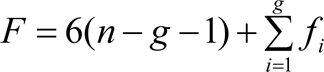
The 3-UPU parallel manipulator, which was presented by Tsai [12], consists of a fixed base and moving platform connected by three serial chains, with each chain having a universal-prismatic-universal joint arranged in sequence. The universal joints are passive and only the three prismatic joints are actuated. The universal joints can be attached in such a way that the moving platform only undergoes pure translational motion. If the passive universal joint can be considered as two revolute joints, the conditions for translational motion is that the outer revolute joint axes of the two passive universal joints are parallel to one another and the two intermediate revolute joint axes are also parallel to one another in each leg. Motivated by these results, some researchers also studied the kinematic of 3-UPU parallel manipulator [13–15]. When Tsai [16] studied the Jacobian matrix of the 3-UPU parallel manipulator, he obtained a significant result. The direct kinematics singularity of the 3-UPU parallel manipulator occurs when any two limbs are parallel to each other. The significant result is that under such conditions the moving platform of the 3-UPU parallel manipulator gains one degree of freedom and can translate freely along a circular path while all the actuators are locked. But he did not study the result further. In fact, the result is not completely correct. The condition that any two limbs are parallel to each other can not be given because no input or geometrical constraint can always satisfy the requirement or condition. The motion of it is determined by the geometrical relationship of the mechanism self. Namely, the kinematic characteristic of it is determined by the layout of the universal joints and other geometrical relationships. In the next section of this paper, we will discuss it in detail. Since the layout of the universal joints for the 3-UPU parallel manipulator has polymorphic possibilities and it is too long to discussed all just in this paper, we only take one of them for example and analyzes its kinematics in singularity. The other cases just give the results.
The three actuated limbs of the 3-UPU parallel manipulator become three fixed-length struts while all the actuators are locked. For the singular condition, here we do not give the condition that any two limbs are parallel to each other as Tsai [16]. Since the centers of the universal joints connected to the moving platform can form an isosceles triangle, and the centers of the universal joints connected to the fixed platform can form another isosceles triangle, we give another singular condition that the two bottom margins of the two isosceles triangles are equal. It is the real geometrical constraint condition. Given the conditions for translational motion and the singular condition, the 3-UPU parallel manipulator can be shown as Fig. 1. For convenient to discuss, we add another condition which is the three fixed-length struts are equal. Since each universal joint consists of two intersecting revolute joints, each limb is kinematic equivalent to an R-R-R-R chain. Starting from the base, let
Kinematic characteristics in singular configuration
Analysis of the degree of freedom
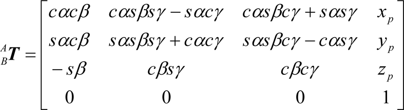
For the degree of freedom of the considered mechanism, it can be calculated by applying the mobility criterion, namely the classical Kutzbach Grübler formula
Where F is the DOF of the mechanism, n is the number of bodies in the mechanism, g is the number of joints and f
t
is the number of degrees of freedom of the ith joint. For the considered mechanism shown in Fig. 1, there are n = 5, g = 6,
One of the singular configuration of the 3-UPU parallel manipulator

The result means the mechanism has no degree of freedom. That is, the moving platform of the mechanism can't move. In order to verify the result calculated by the Kutzbach Griibler formula, we will derive the analytic expressions of motion for the moving platform and analyze the degree of freedom of the mechanism of it in the next section.
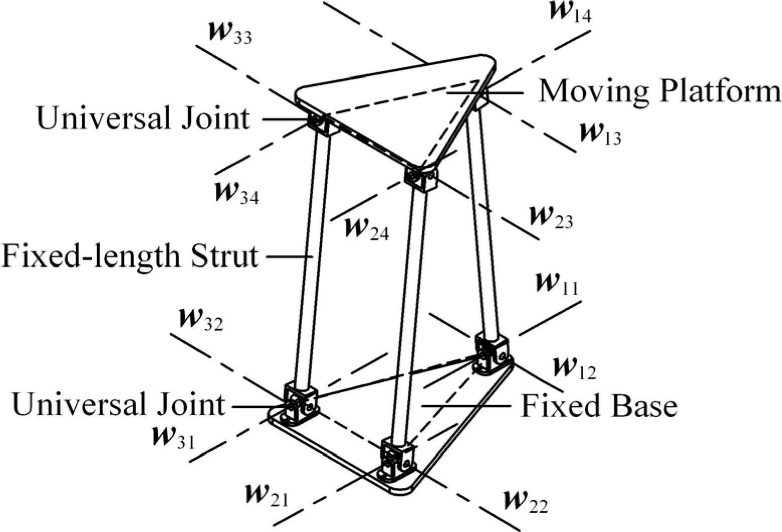
For convenient to describe, the considered mechanism can be schematic represented as Fig. 2. As shown in Fig. 2, the centers of the universal joints connected to the moving platform are denoted by B i (i = 1 ∼ 3). Similarly, these connected to fixed platform are denoted by A i (i = 1 ∼ 3). Points D1 and D2 are the pedal of bottom margins A2A3 and B2B3, respectively. Assuming that a base coordinate O A X A Y A Z A is embedded in the fixed platform and a moving coordinate O B X B Y B Z B is embedded in the moving platform. As shown in Fig. 2, the origin of the base coordinate is located at the midpoints of the line A1D1. The axis Z A lies in the base plane formed by the points A1, A2 and A3, and axis Z A is through the point A1. The axis X A also lies in the base plane and is normal to Z A axis. The axis Y A is normal to the plane spanned by axes X A and Z A . Similarly, the origin of the moving coordinate is located at the midpoints of the line B1D2, the axis Z B lies in the moving plane formed by the points B1, B2 and B3, and axis Z B is through the point B1. The axis Y B is perpendicular to the moving plane. The axis X B is normal to the plane spanned by axes Z B and Y B .
The schematic representation in the singular configuration
Moreover, the link coordinate O ij X ij Y ij Z ij (j denotes serial numbers of the link coordinate in each limb, j = 1 ∼ 4) in the ith limb is established based on the D-H (Denavit-Hartenberg) method. Its origin O ij is coincident with the center of corresponding universal joint. The D-H parameters of the i th chain are shown in the Table 1. And ai(j−1) denotes the distance from the axis Zi(j−1) to the axis Z ij , d ij denotes the distance from the axis Xi(j−1) to the axis X ij . The angle αi(j−1) is measured from the axis Zi(j−1) to the axis Z ij , the angle θ ij is the rotation angle of the j th universal joint around the corresponding axis. For convenience to the analysis, we make some assumptions as follows: the Zi0 and Zi1, Zi4 and Zi5, Xi4 and Xi5 axes are parallel to each other, respectively. In addition, the planes Xi4Zi4 and Xi5Zi5 are completely coincident, the coordinate Oi5Xi5Yi5Zi5 and O B X B Y B Z B , Oi0Xi0Yi0Zi0 and O A X A Y A Z A are completely coincident as well, respectively. For the pose of the mechanism shown in Fig. 2, θi1 = −π/2.
The D-H parameters of the ith limb

Based on the D-H parameters in table 1, the pose transformation matrix of the moving platform with respect to the base coordinate can be obtained for the ith chain and can be expressed as

where j−1
j

where
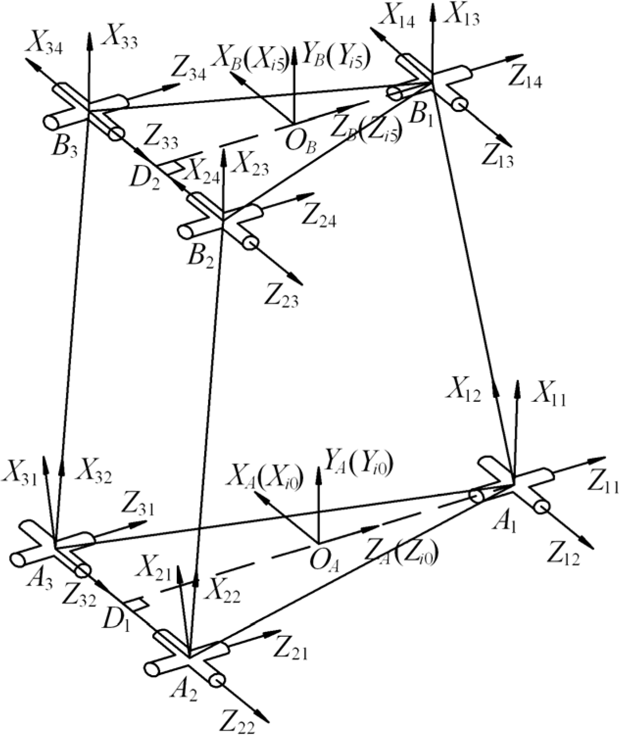
Taking Euler angles as variables, the pose matrix of the moving platform in the base coordinate can also be described and can be written as
where α, β and γ denote the three successive rotations of the moving platform around the axes Z A , Y A and X A , respectively. The x p , y p and z p denote the co-ordinate of the point O A in the base coordinate.
According to the structural features of the 3-UPU parallel manipulator in singular configuration shown in Fig.l, there are three constraint equations can be obtained as follows

Since the three chains have the common end-effector, namely the moving platform, the following constraint equations can also be obtained

For convenience to analyze, let

where


In fact, the analysis of the kinematic characteristics of the 3-UPU parallel manipulator in singular configuration is just solving the kinematic and constraint equations above. For be helpful to describe, let A1D1 = d1, B1D2 = d2, A2A3 = B2B3 = a and A i B i = l. According to the structural features shown in Fig. 2 and the D-H parameters above, there exist the following expressions which are satisfied with: d11 = −d21 = −d31 = d1/2, d2T = d3T = −d1T = d2 / 2, a30 = −a20 = a/2, a24 = −a34 = a / 2, ai2 = l, a10 = a14 = 0 (i = 1∼3). So Eq. (3) can be rewritten as

where

Let

From the Eq. (15), the relationship is obtained

From the simultaneous equations (16) and (17), the following expression can be obtained

According to the above results, the following two cases have to be discussed: (1)
θi1 = −θi4, s(θi2 + θi3) ≠ 0,
Substituting the condition θi1 = −θi4 into constraint expressions n1x = n2x and n1y = n2y in the Eq. (11) yields

Since in this case s(θi2 + θi3) ≠ 0, there is m ≠ 1. It is substituted into Eqs. (19) and (20), then combining them yields θ11 = θ21. Similarly, combining the constraint equations n1x = n3x and n1y = n3y in the Eqs. (11) leads to θ11 = θ31. If let θ11 = φ0, one can obtain θi1 = φ0 and θi4 = −φ0, i = 1∼3, in which φ0 ∊ (−π, 0) and sφ0 ≠ 0.
Combining the two expressions p1y =p2y = p3y and p1z = p2z = p3z in the constraint equations (14) yields

Then Eq. (21) can be further rewritten as

where
The coordinates of points A
i
and B
i
in the base coordinate are obtained by the transformation matrixes


where

Let

where

One can get t22 = t32 or
If
In addition, the relationship p2y = p3y in Eq. (14) can be rewritten as

Since the

Assuming that θ12 is an input variable, θ22 can be determined by Eq. (27). Substituting θ22 into Eq. (23) and (24) can further solve for θi3 (i=1∼3). Because θ22 and θi3 are all the function of θ12, let θ22 = f1(θ12), θ13 = f2(θ12) and θ23 = θ33 = f3(θ12). Then they are substituted into Eq. (15). The pose transformation matrix of the moving platform can be rewritten as
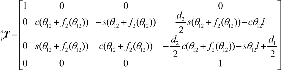
It is very clear that the matrix
A
p
In this case, since the range of
Combining the expressions n1x = n2x, n1y = n2y and n1z = n2z in the Eq. (11) yields

Similarly, from the expressions n1x = n3x, n1y = n3y and n1z = n3z in the Eq. (11), it can be obtained

Then, combining the above Eq. (29) and (30) in terms of

Let

Obviously, it is very easy to eliminate θ11 by combining the first two equations in Eq. (32). The sixth equation in Eq. (32) can derive the result θ32 = θ22. It is substituted into the fourth and fifth equation in Eq. (32), and combining the two equations can eliminate θ31. Then θ12 can be eliminated by the rest of equations in Eq. (32). Finally, Eq. (32) can be furthered represented as
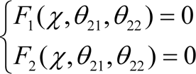
Eq. (33) has three variables θ21, χ and θ22. If θ21 is given, one can calculate χ and θ22 by the Eq. (33). Then substituting the χ and θ22 into Eq. (32) can obtain θ11, θ12, θ31 and θ32. Hence, the value of θ13, θ14, θ23, θ24, θ33 and θ34 can all be solved. The results are shown as follows
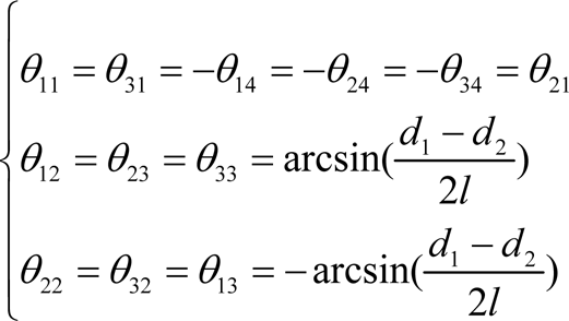
If the Eq. (34) is substituted into Eq. (15), the pose transformation matrix of the moving platform can be expressed as

The Eq. (35) is the function only about the variable θ11, which means that the singular mechanism has one degree of freedom when s(θi2 + θi3) = 0 (i = 1∼3), namely θi2 + θi3 = 0. Besides, from the Eq. (35) it can also be seen that the moving platform can perform a pure translational motion in the plane O A − X A Y A . The kinematic characteristic of the mechanism in such condition is similar to the one of the parallelogram mechanism.
The structural parameters of the mechanism are assigned as: d1 = 250mm, d2 = 150mm, l=500mm, a=100mm. Let θ11 = −π/2 and taken θ12 ∊ (−π/2, π/2) a set of numbers as inputs, the other rotary variables θ ij (i ≠ 1, j ≠ 1,2) can be determined. Similarly, let θi2 + θi3 = 0 and taken θ21 ∊ (−π, 0) a set of numbers as inputs, the others can also be solved. By combining the Eq. (5) and Eq. (15), the pose parameters α, β, γ, x p , y p and z p in both cases above can also be determined. The results are listed in table 2 and table 3, where units of α, β and γ are radian, units of x p , y p and z p are millimeter, and “–” denotes no solution.
Numerical calculation results in the case of θ11 = −π/2

Numerical calculation results in the case of θi2 + θi3 = 0 (i=1∼3)

From the table 2, one can know that the range of the motion for the moving platform is small. It is limited by the structural parameters of the mechanism. The corresponding trajectories of the moving platform are shown in Fig. 3 and denoted by the Tra2 and Tra1 for the first and second cases. When the mechanism is in the Tra1, one of joints related to the

Motion trajectories of the moving platform in different case
However, in the Tra2 the actuator turns into one of joints related to the
Although the dimensions of the motion of the moving platform for both the cases exceed two, the degree of freedom of the 3-UPU parallel manipulator in the singular configuration is one. It is the reason that the motion of the moving platform is just depended upon one of the joint parameters of the mechanism. Besides, one can know that the moving platform of it can move. The moving platform has no degree of freedom from the foregoing calculation by the Kutzbach Grübler formula. It shows that the formula to calculate the degree of freedom for the parallel manipulator is not always valid.
In order to verify the above analysis, the motion of the 3UPU parallel manipulator in the singular configuration is simulated using the COSMOSMotion plug of the software SolidWorks.
If one of three outer revolute pairs connected to the fixed platform is actuated, it can be seen from the simulation that the three fixed-length struts rotate around the axis

The motion of moving platform when one of axes
However, it must be paid attention that the mechanism is unstable when the moving platform of mechanism moves right above the fixed platform. At the moment the three fixed-length struts may also rotate around

The motion of moving platform when one of axes
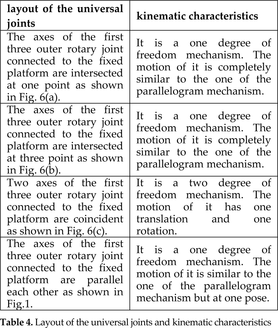
In fact, there are other cases for the layout of the universal joints and the kinematic characteristics of them are different from the one above if the passive universal joint can be considered as two revolute joints. Of course, the cases are too many. It is too long to discuss them one by one analytically. Here we just give some typical cases and their kinematic characteristics. The common conditions are the three fixed-length struts are equal and bottom margins of the two isosceles triangles formed by the centers of the universal joints connected to the moving platform and fixed platform respectively are equal. Table 4 is the partial typical layouts and their kinematic characteristics.
Layout of the universal joints and kinematic characteristics
Layout of the universal joints and kinematic characteristics

Three different layout of the universal joints
Since some of the kinematics characteristic of the 3-UPU parallel manipulator in the singular configuration is similar to the one of the parallelogram mechanism, it can be constructed as the passive mechanisms as shown in Fig. 1, Fig. 6(a) and Fig. 6(b). Thus the passive mechanisms can constrain the moving platform output to translation motion along a circular path in a plane. Based it, some 2-DOF parallel translating manipulators can be constructed as shown in Fig. 7. In Fig. 7, two limbs connect the moving platform to the fixed platform. Each limb consists of an actuated linear slide and the passive mechanism constructed by the kinematics characteristic of the 3UPU parallel manipulator in the singular configuration. The motions of the two actuated linear slides are at the same line or parallel each other. Since all limbs are connected to the moving platform and fixed base by universal joints, no bending moments can be transmitted to the limbs. Thus, force exerted on each limb is necessarily pointing along the longitudinal axis of the limb and the only moment exerted on each limb is a twisting moment. Hence, the limbs can be made up of hollow cylindrical struts to achieve a light-weight and high-stiffness manipulator. Besides, it gives the 2-DOF translational parallel manipulators a good architecture to resist the force which is perpendicular to the kinematics plane. And its rigidity perpendicular to the kinematics plane is higher than the one of the 2-DOF translational parallel manipulators based on the parallelogram mechanism.

The parallel translating manipulator with the linear slide actuated

The parallel translating manipulator with the rotation actuated
Fig. 9 is the other application of the singular mechanism. In Fig. 9, two compound limbs connect the moving platform to the fixed platform. Each compound limb consists of an actuated rotating arm and two passive mechanisms presented above. The actuated rotating arm is parallel to the passive mechanism connected with the fixed platform. The two passive mechanisms are connected serial between the moving platform and the fixed platform. The actuated joints of parallel robot are revolute joints and it is would be most suitable for developing a high speed and low-cost device for pick-and-place operations.
In this paper the kinematic characteristics of the 3-UPU parallel manipulator in one of singular configurations are studied. Based on the kinematics characteristics of it, some applications are analyzed. From the discussion in this paper, some conclusions can be drawn as follows.
The motion of the 3-UPU parallel manipulator in singular configuration is relevant to the layout of the joints. If we go further into the question, the layout of the joints may have great influence on the motion of the moving platform of parallel manipulator. So it must be considered when some new parallel mechanism is constructed firstly with synthesis method of mechanism, especially the enumeration method. Besides, the formula to calculate the degree of freedom for the parallel manipulator is not always valid. Although the dimensions of the motion of the singular mechanism exceed two, the degree of freedom of it may be one. The dimensions of the motion and the degree of freedom for mechanism are two different concepts. The number of the degree of freedom for mechanism is determined by the one of the independent input variables. The number of the degree of freedom for mechanism can exceed six. But the dimensions of the motion do not exceed six in Cartesian coordinate. In the foregone research, singularity is mostly thought as the bad pose of parallel manipulator and must be avoided inside the workspace. So few literatue is paid attention to the kinematic characteristics of the parallel manipulators in singular configuration. The application of the kinematic characteristics in singular configuration is even few. Just as every coin has two sides, the kinematic characteristics of some singular architecture may be utilized for compound limbs of parallel manipulators from the discussion above in this paper. Based the kinematic characteristics of 3-UPU parallel manipulator in singular configuration, some new planer parallel manipulator is presented. Some passive spatial joints such as the universal joint and the spherical joint can be used in the planar parallel manipulator. Compared with the use of the passive planar joints such as the rotary joint and the prismatic joint, planar parallel manipulator used the passive spatial joints can improve the stress and give it higher rigidity, especially the direction of perpendicular to the kinematics plane. The reason is that the strut of the planar parallel manipulator connected to the passive spatial joints at the two ends does not bear the bending moment. It gives the planar parallel manipulator a good architecture to resist the force which is perpendicular to the kinematics plane. So its rigidity perpendicular to the kinematics plane is higher than the one of the general planar parallel manipulators. The 2-DOF planar parallel translating manipulator presented in this paper is a good example.
Footnotes
8.
The research work is jointly sponsored by the NUST Research Funding (No:2010ZYTS007) and the open foundation of the Key Laboratory for Digitized Manufacturing Technology of Jiangsu province (No:HGDML0707).