
Abstract
This article presents a novel spatial parallel mechanism with kinematic redundancy. The design strategy and evolution of the proposed mechanism is introduced, and kinematic model of the mechanism is established. To simplify singularity analysis of this kind of mechanism, the virtual plane method which can separate the whole parallel mechanism into two parts is presented. The relative Jacobian matrices are established and illustrated with singularity configurations of three types. Kinematic performance is obtained to see redundancy effects on the mechanism. The orientational workspace is obtained by the regions of orientational angles with varied platform position. It shows the orientational workspace of the redundant mechanism is significantly larger. Evaluation of condition number demonstrates the proposed mechanism can clearly stay away from singularities with a large range of rotational angles. A trajectory example is conducted to further prove the proposed mechanism can produce a large range of rotational angles without meeting with singularities.
Introduction
It is widely known that spatial parallel mechanisms (PMs) possess many advantages compared to serial mechanisms in the areas include manufacturing, motion simulation, and pick and place manipulation. Such benefits include higher stiffness, higher payload ability, higher acceleration, the solution to inverse kinematics problem is simpler, the position of actuators located in or near to the rack. 1 However, the aforementioned advantages often suffer lower dexterity performance, finite smaller workspace, more complex kinematic models, and dynamic models. The additional complexity of these kinematically constrained architectures is more than that of serial mechanisms. 2
So far, most of the proposed PMs in the literature have focused on architecture with nonredundant. In a bid to overcome the aforementioned drawbacks of PMs, the redundant PMs have been proposed. 3 Totally, only three redundancy types were defined by Lee and Kim 4 and can be separated into two types. One is kinematic redundancy and the other is actuation redundancy, which can include all three redundancy types. 4 Many researchers proposed the actuation redundancy PM to alleviate the disadvantage such as limited rotational capability 5 –11 . Generally, the majority of actuation redundancy studies have focused on replacing some or all existing passive joints by active joints or adding additional limbs to connect the fixed base with moving platform. The studies of adding additional limbs are more probably to avoid singularities. However, actuation redundancy mechanism does not alter mobility. Besides, adding actuation redundancy may alleviate or eliminate its singularities but not change the mechanism’s workspace. Unfortunately, this method can generate internal forces between links and moving platform. Therefore, controlling of such mechanisms requires the advanced controllers and becomes more challenging. 12 –14
In recent decades, other researchers have proposed the PM with kinematic redundancy to eliminate or reduce singularities.
2,3,15,16
This method is introduced by adding extra active joints into the limbs to improve the capacity to modulate the limbs or avoid singularities. The kinematic redundancy research on high applicable nonredundant PMs such as 3-R
To make the mechanism structure overcome the above disadvantages, a novel PM with kinematic redundancy is proposed by introducing five-bar structure into each limb. The evolution of the novel redundant PM is briefly introduced as shown in the “Architecture of the kinematically redundant mechanism” section. In the “Kinematic model” section, the kinematic model of the redundant PM is provided. Based on the proposed virtual plane (VP) method for decreasing difficulty of singularity analysis, the configurations of three singularity types are discussed and some of the configurations are illustrated in the “Singularity analysis” section. Then, the orientational workspace of the proposed 3-
Architecture of the kinematically redundant mechanism
Evolution of 3-RR RRRS mechanism from the 3-RP S mechanism
The architecture of MaPaMan
19
was introduced by the evolution of the 3-R
The evolution is shown in Figure 1 and described as follows: (1) Prismatic actuator (
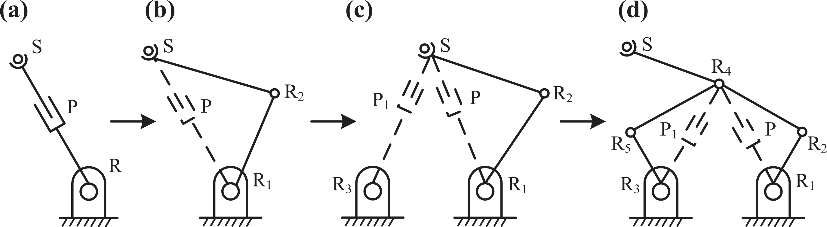
The evolution of the limb architecture. (a) RPS architecture; (b) RRS architecture; (c) RRRPS architecture; (d) RRRRRS architecture.
Architecture of 3-RR RRRS mechanism
Three identical limbs connect fixed platform with moving platform to form the mechanism. The moving platform is designed as a rigid equilateral triangle form, which acts as the output manipulator of the mechanism. Architecture of the mechanism and details of the first limb are shown in Figure 2. The limb consists of a five-bar linkage and a strut link. The five-bar linkage is actuated by two actuators located at Ai and Ei , respectively. The motion is produced by the strut link attached to the output rotational joint (Ci ) of five-bar linkage. Ci is in the strut base and transmits motion to moving platform via the strut link. Then, the coordinate frames O-xyz and p-uvw are set up in the center of fixed platform and moving platform, respectively.
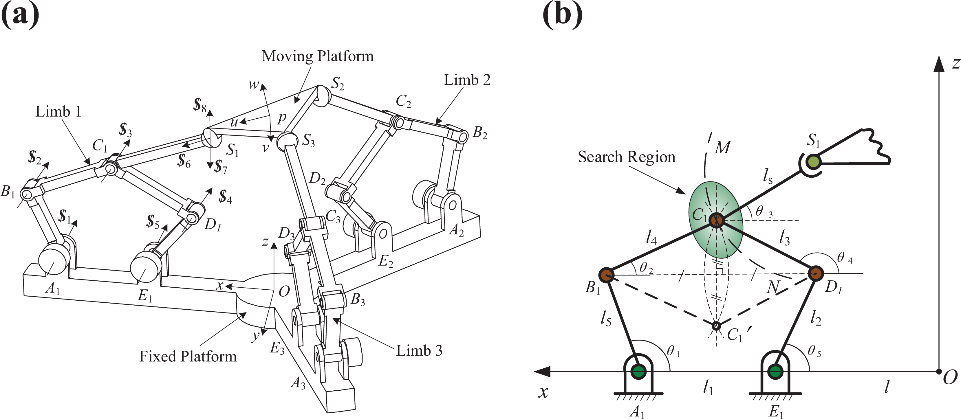
Architecture of 3-RRRRRS mechanism and kinematic diagram of limb 1. (a) The 3-RRRRRS mechanism Architecture and (b) Kinematic diagram of limb 1.
DOF and RDOF of 3-RR RRRS mechanism
The degree of freedom (DOF) of the mechanism is the number of independent actuators that needed to define a unique configuration. The rotational degree of freedom (RDOF) of the mechanism is equal to the number of independent motions of moving platform. In the kinematically redundant mechanism, the DOF of the whole mechanism is not equal to the RDOF between the moving platform and the fixed base.
22
In this section, the RDOF and DOF of the mechanism are calculated to show the proposed mechanism has a structure with kinematic redundancy. As shown in Figure 2, the coordinates of kinematic joints center (Ai
, Bi
, Ci
, Di
, Ei
, Si
) can be noted as

Assuming the direction of three equivalent rotation axes of joint S 1 respectively along the x-, y- and z-axes, screws of joint S 1 can be written as
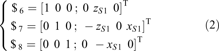
Based on equations (1) and (2), the screw system of limb 1 can be obtained as

Then, the reciprocal screw of screw system of limb 1

where
Due to the symmetrical properties of this PM, there are three restraint force vectors focus on the moving platform. The vectors are parallel to the revolute joints axes in each limb respectively. Assuming that the initial position is when moving platform is parallel to fixed platform, the three restraint force vectors are coplanar consequently. Then one can be obtained is that the three restraint force vectors are linearly independent. This means that the movement of the moving platform along the x- and y-axes and the rotation around the z-axis are restricted. Therefore, the RDOF of the moving platform is the movement along the z-axis and the rotation around the x- and y-axes.
In this section, the modified Grübler–Kutzbach equation (5) is used to find the DOF of this mechanism. Due to the 3-

where M is the DOF of the mechanism, d is the order of mechanism, d = 6 − λ, λ is the number of common constraints on the mechanism, n is the total number of links of the mechanism, g is the total number of the joints of the mechanism, fi is the number of degrees of freedom of the ith joint, and v is the number of redundant constraints of the mechanism.
To get the number of redundant constraints v, the reciprocal screw of
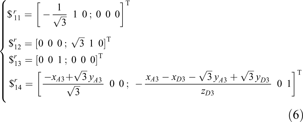
Then, the reciprocal screws of
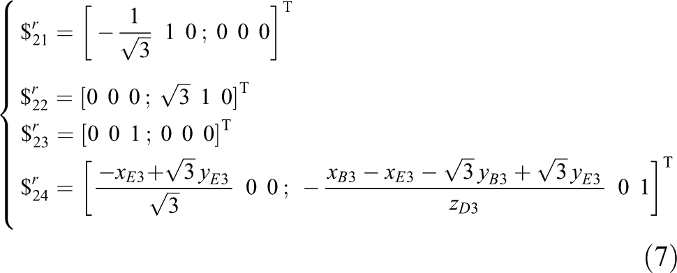
Comparing equation (6) with equation (7), three groups of reciprocal screws are the same (
The DOF of the mechanism can be calculated by equation (5)

Therefore, the calculation results of DOF and RDOF demonstrate the mechanism is a kinematically redundant mechanism. In this article, Ei is selected as the redundant actuation.
Kinematic model
Referring to Figure 2, the limb architecture of the redundant mechanism contains an actuation unit (five-bar linkage) and a strut link (l s). The design purpose of the redundant mechanism is to furthest reducing the passive joints number to simplify the calculation of kinematic problem. It is obvious to observe that the actuation unit of each limb contains mostly all passive joints.
Therefore, to simplify symbolic expressions involved the active and passive variables, the positions of Ci
are selected as output of actuation units and expressed by active variables θ
1i
, θ
5i
. Where θji
is the joint θj
in the ith limb, θ
3i
is the function involved active variables θ
1i
, θ
5i
and the geometric link parameters. The position of Ci
is noted by a vector


where
By solving equations (9) and (10), the position of C 1 can be obtained. Here, the result is two sets of solutions for C 1, which corresponds to the two locations of C 1 as shown in Figure 2. The solution corresponding to the protruding C 1 is chosen.
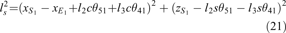
The coordinate of point S 1 can be expressed by the active variables θ 11, θ 51 and passive variable θ 31

where
The symmetric architecture makes it easy to obtain the coordinates of points S 2 and S 3 in the other two limbs. Assuming that limb 2 and limb 3 are in the x–z plane as the same case as limb 1, coordinates of S 2 and S 3 can be obtained through replacement of subscript “1” by “2” in equation (11). Then the actual coordinates of S 2 are easy to be found by rotating this vector through 120° about the z-axis. The actual coordinates of S 3 can be obtained in a similar method


In equations (12) and (13),
Forward kinematic
Due to the moving platform is designed as a rigid equilateral triangle form, the geometric constraint is that the points S 1, S 2, and S 3 can form an equilateral triangle architecture, which can result in the constraint equations. Hence, the constraint equations can be formulated as


where ht is the side of the equilateral triangle formed by the points S 1, S 2, and S 3.
Put the above three equations in a vector

At this stage, it only remains three unknown variables (θ 31, θ 32, and θ 33) to solve in equations (14) to (16). Computations of these variables lead to the derivation of a 16-degree univariate polynomial equation. 23 The method of getting these unknown variables can be seen in Sagi and Bandyopadhyay 18 . After calculation of θ 3i , the coordinates of points S 1, S 2, and S 3 can be obtained to find the position and orientation of moving platform.
Inverse kinematic
Kinematically redundant mechanisms have an infinite number of possible solutions of inverse kinematic. Therefore, if there are any, there may be one or some loci of solutions instead of the finite solutions. Figure 2 describes a case about the locus of solutions. The search region in Figure 2 is an assuming area that point C 1 of five-bar linkage can reach based on the maximum and minimum actuation angles of θ 1, θ 5. In the inverse kinematic solution, if the moving platform location is given, then all possible locations of point C 1 are the points on the circle of radius l s centered at S 1. Therefore, all possible solutions of θ 1 and θ 5 are the intersection of the aforementioned region and location, which are located on the MC 1 N arc.
In the inverse kinematic solution, the moving platform Cartesian coordinates are obtained by the vector of the central point p, noted by

Hence, the center position vector of the ith spherical joint, which connects limb i with the moving platform can be obtained as

where
As shown in Figure 2, the constraint equation in terms of link l s length connecting points Si with Ci can be written as

When the orientation and position of the moving platform are given, the point Ci of every limb has a possible locus of location for the inverse kinematic solution as shown in Figure 2. Since each constraint equation contains two unknown variables (θ 1i and θ 5i ), there is an infinite solution for θ 1i and θ 5i to generate Ci located on the MC 1 N arc. If θ 1i and θ 5i are determined as actuated angles, one of the angles θ 1i and θ 5i should be given first.
Jacobian matrix of the 3-RR RRRS mechanism
The output parameters of the mechanism can be noted by


where θ 4i is the function of the two actuation angles (θ 1i and θ 5i ) and link parameters of the five five-bar linkages. The symbols xSi , ySi , and zSi are the coordinates of sphere joints Si , which include the output parameters of the moving platform.
Assuming
The direct and inverse matrices (


Hence, the overall Jacobian matrix

where the aij , ui , and vi are the functions of α, β, z, θ 1i , θ 5i and link parameters, i, j=1, 2, 3.
Singularity analysis
Currently, three types of singularity of closed-loop kinematic chains are presented based on the inverse Jacobian matrix (
In the “DOF and RDOF of 3-

The illustration of virtual platform formed by C 1 C 2 C 3.

The configuration of virtual parallel mechanism in the initial position.
In Figure 4, the symbol r is defined as circumradius of the equilateral triangle C
1
C
2
C
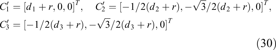
3 in initial position. It is obvious that locations of Ci
will be changeable with the motion of five-bar linkage actuated by θ
1i
and θ
5i
. The new locations of Ci
are noted by

The illustration of initial configuration and the arbitrary configuration in the moving process.

Top view of the virtual plane
As r is the circumradius of the triangle C
1
C
2
C
3 when moving platform is in the initial position, di
can be regarded as the distance produced by the initial point Ci
that moves to point
Consequently, the initial mechanism 3-
Singularity analysis of the actuation units
The actuation units are composed by five-bar linkage AiBiCiDiEi (I = 1, 2, 3) of three limbs. Whatever the mechanism configuration is, the output points Ci of limbs can always construct a plane C 1 C 2 C 3. The plane C 1 C 2 C 3 is named as virtual platform. Generally, singularity occurs in any of the possible conditions: (1) singularity occurs in one or more limbs of five-bar linkage; (2) singularity occurs in PM constructed by virtual platform; and (3) singularity occurs when both conditions (1) and (2) are satisfied.
The singularity configurations of plane five-bar linkage can be obtained by Jacobian matrices. As shown in Figure 2, two constraint equations can be obtained to solve the kinematic problem

The Jacobian matrix

where
The determinant of

When singularity occurs in five-bar linkage, the condition is Det(
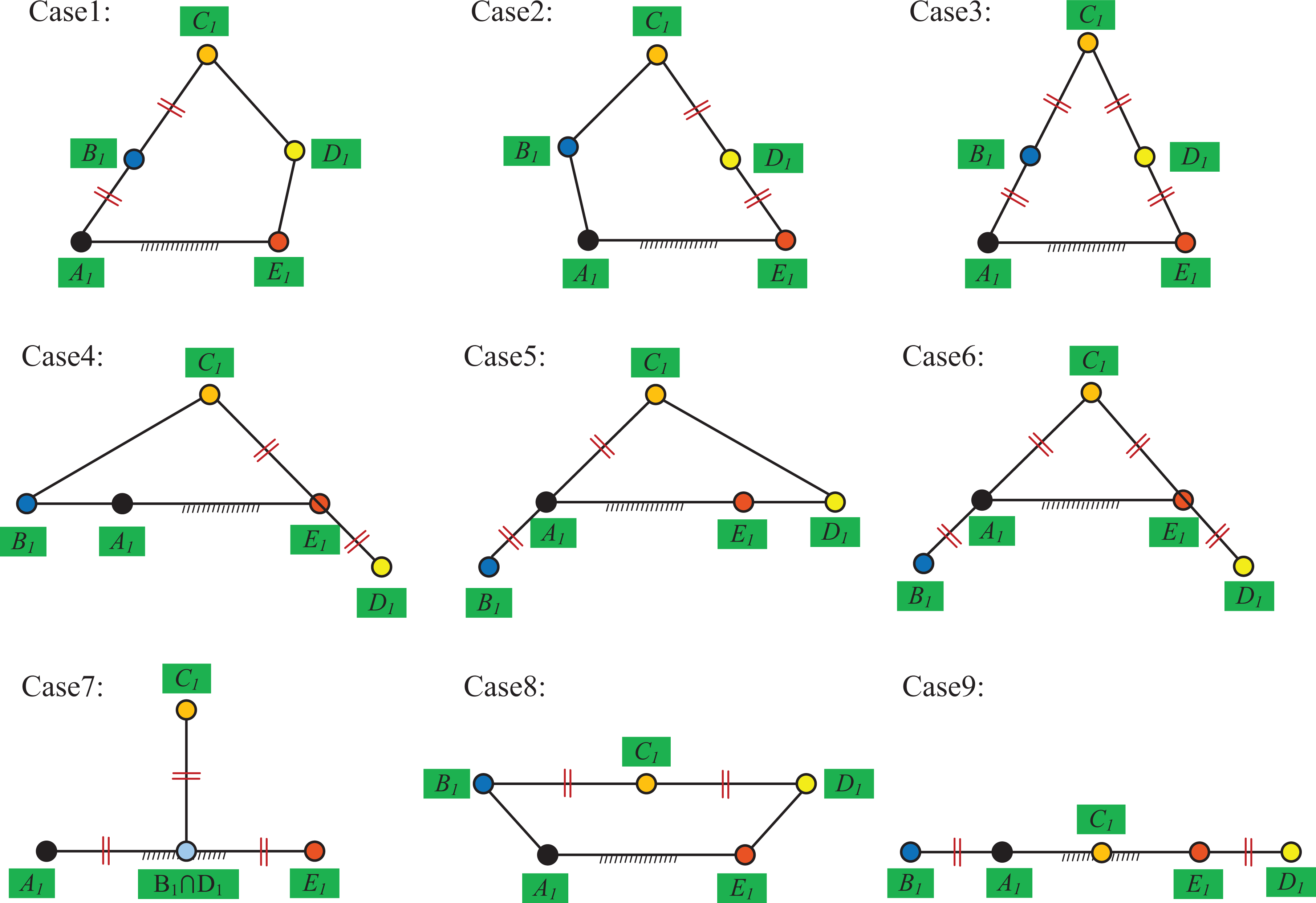
Singularity configurations in different conditions.
It is easy to obtain that there are only nine singularity configurations of five-bar linkage in each limb as shown in Figure 7. Figure 8 is the topological diagram of the proposed mechanism. Si
represents the strut link, and Fi
stands for five-bar linkage in each limb. The red area is the moving platform. In Figure 8, Ci
stands for case i of singularity configuration and 0 stands for non-singularity configuration. These nine singularity configuration cases are noted by Ci
in each limb as shown in Table 1. If the five-bar linkage of each limb meets singularity, it means inverse singularity or boundary singularity occurs in the 3-

Topological diagram of the proposed 3-
Singularity configurations in each limb.

Considering there are nine singularity configuration cases in each limb, the singularity types of three limbs can be concluded in Table 2. As shown in Table 2, singularity type is the number of limbs that is in singularity configurations. The combinations when occurring singularity cases can be calculated through combinations of these nine cases among three limbs. If only one limb and no matter which one occurs singularity, it belongs to singularity type 1 case in combinations. Hence, the combination number in three singularity types can be written in Table 2 by means of permutations and combinations. Singularity types 1, 2, and 3 in case 3 configuration are illustrated in Figure 9.
The types of singularity configurations.


Singularity types 1, 2, and 3 in case 3 configuration.
Singularity of the virtual PM
The other one of the singularities of 3-
In the virtual PM 3-

where
Using the same method as in the “Jacobian matrix of the 3-
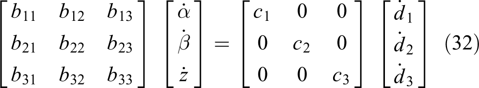
where the bij and ci are the functions of α, β, z, di and link parameters, i, j = 1, 2, 3.
When the determinant of

Configurations of the singularity caused by the virtual PM.
Combined singularity of the 3-RR RRRS5
As previously described, the combined singularity occurs when both the five-bar linkage and the virtual 3-

Combined singularity configurations of the 3-
However, adding redundant actuation joints in the other two limbs can help to avoid singularity configurations by changing the direction of link CiSi
. As a result, this would be prevented that any of links CiSi
are parallel to the platform S
1
S
2
S
3 or all the links CiSi
intersect at a common plane S
1
S
2
S
3. The configurations of the third case are shown in Figure 11. Reminding the initial purpose, one of the purposes is adding these redundant revolute joints to avoid singularities. The avoidance of the typical singularity can be realized by using the five-bar linkage to control the direction of link CiSi
. The controlling strategy is not developed in this article, and future work will focus on the control strategies. Another purpose is workspace will be increased by adding the redundant joints. The workspace analysis of 3-
Performance analysis
Workspace analysis
In the traditional PM, there are many factors to limit the region of workspace. Whereas the main factor is the singularity configurations occurring, especially the configuration that link CiSi is parallel to the moving platform. The purpose of adding redundancy is to adjust the direction of the link CiSi through redundancy actuation to avoid singularity, so that the moving platform of the mechanism can generate large rotational angle motions. As shown in the “Singularity of the virtual PM” section, all Cartesian positions and poses of the moving platform can be met with one non-singularity configuration at least. Such as link CiSi is not coplanar with plane S 1 S 2 S 3 of the proposed mechanism. In this section, the workspace is used to demonstrate that the redundancy can reduce the limitation of motion ability. For the purpose of providing a visualized workspace of the mechanism, the necessary evaluation of the orientational workspace is more effective than the evaluation of the translational workspace. The orientational workspace is mapped by the ranges of orientational angles (α, β) with varied moving platform position (z). The procedure was completed in this section. For a given position z incremented by steps of one unit (mm), the angle (β) will be a traversal of 360° when incremented by a step size of 1°. Then, to every values of angle β, the moving platform is pitched by torsion angle (α) incremented by a step size of 1° When actuator limits or singularity configuration is determined, then incrementations of z and α will stop. In this section, dimension parameters of this mechanism and actuator limits are presented in Table 3. The orientational workspace is mapped as shown in Figure 12 with the regions of α, β, and z. In this section, passive joint limits and limbs interfere with the moving platform are not considered. Thus, the obtained result can be regarded as an upper boundary of the workspace.
Geometric parameters of the mechanism (all lengths in mm).


Orientational workspace of the architecture of Table 3.
The results are shown in Figures 12 to 14. Cylindrical coordinates system is used in this demonstration. In Figure 12, the z-axis measures the platform position (z), and the color varied with the z scale that goes from −60 mm to 60 mm. Figure 12 shows the workspace is projected to the z = 0 mm plane. Here, the hollow dots are invalid region that they don’t satisfy the limits in Table 3, and the red dots are valid region. As shown in Figure 12, the yellow line represents the minimum boundary of the valid region, where α = 40°. In Figure 14, the angle (α) is measured by the radius direction, and the angle (β) is measured by the peripheral direction. It can be observed that the maximum pitched angle (α) can reach 90° in a certain direction, while the pitched angle will yet reach about 50° in the worst direction. Therefore, a large orientational workspace is obtained with the proposed structure, even the combination of rotations exists. Figure 15 shows two special cross-section view of the workspace, the orientation workspace is symmetric with respect to A–A cross section. The results are consistent with the structural symmetry of the mechanism.

Projected orientational workspace.
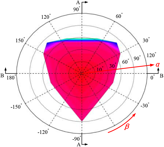
Top view of the orientational workspace.
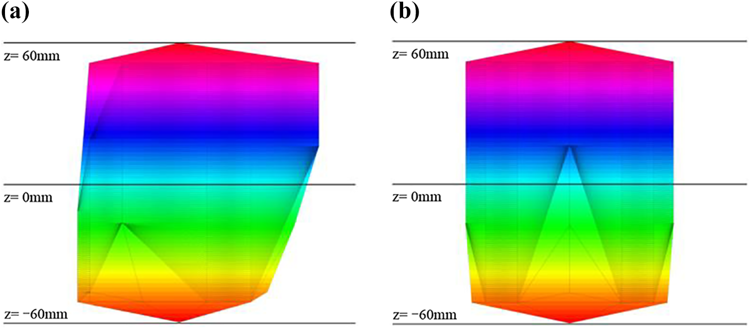
Special cross-section view of the orientational workspace: (a) A–A cross-section view and (b) B–B cross-section view.
Dexterity analysis
In this section, the condition number noted by κ is chosen as the performance index to demonstrate the mechanism can stay away from singularities. Thus, the value of κ can be obtained through the matrix

where
Figure 16 shows the performance index κ varies with orientational angles α and β. Figure 16 shows the evaluation of index κ varies with α under the conditions of β = 0, Pi /6, and Pi /3. Figure 16 shows the evaluation of index κ varies with β under the conditions of α = 0, Pi /6, and Pi /3. The vertical axis represents variation of index κ. The abscissa axis represents variations of α and β.

Evaluation of κ varies with orientational angles α and β: (a) the relationship between κ and α and (b) the relationship between κ and β.
It can be observed that the performance index never exceeds 8 under different conditions of β in Figure 16. Referring to Figure 16, the performance index with α varied in different values of β is slightly lower than that of the former case. All the condition numbers are a constant less than about 8, and the values near the center are close to 1 in the evaluation. It should be noted that the interference of limbs and moving platform is not considered in this case. This cause the large angles range in abscissa axis. Nevertheless, the results show condition numbers are constant, not infinity, namely the mechanism can clearly stay away from singularity.
Trajectory simulation
A circle trajectory is performed by simultaneously giving the moving platform a distance from 0 to x max along the u-axis and another distance from 0 to y max along the v-axis, which can be seen in Figure 17. The composite motion of two direction displacements can make the center point p of the moving platform perform a circle trajectory. 28 To demonstrate, the mechanism can produce the large rotational angles without occurring singularities, the range from 0 to x max and y max should correspond to or contain large angle values of α and β. In addition, the obtained variation curves of actuators should be continuous because the actuators have no values when the mechanism is in singularity configuration.

Trajectory simulation: (a) 3-D model of trajectory simulation, (b) top view of trajectory simulation, and (c) geometry trajectory of the point p.
The relationship between the positions (x, y) and the rotational angles (α and β) can be obtained by the structural characteristics of the mechanism. Referring to Figure 17, three limbs maintain an angular separation of 120° symmetry in the architecture of the mechanism, which are caused by the equilateral triangle structure of the moving platform.
The five-bar linkage restrains the joints Si
will always be located in the plane AiBiCiDiEi
. Hence, the relationship between coordinates (x, y) of Si
maintains the expressions

Here,

Hence, according to equation (35), when we determine the value of x and y, then the value of α and β will be obtained. If α and β are in the range of values in the workspace, then the given values of x and y are feasible. Here, we give the value of x max and y max is 10, so that the value range of x and y can demonstrate the moving platform will produce a larger angle when it performs the circle trajectory. In addition, to get a valid set of solutions from an infinite number of inverse kinematics, the given constraint condition is linked to CiSi which is not coplanar with S 1 S 2 S 3 platform in the simulation.
Figure 18 shows the variation curves of actuators (θ 1i and θ 5i ) in the process of moving platform performs the circle trajectory, where the initial position is defined as the fixed platform is parallel to the moving platform. In Figure 18, “theta i” represents “θ 1i ” and “elta i” represents “θ 5i ”, i = 1, 2, 3. It can be observed that the cosinoidal and sinusoidal displacements of moving platform in the x-axis direction and the y-axis direction are varying from 0 mm to 10.0 mm, which can produce a circle trajectory. The variation is measured by the right vertical axis. According to equation (35), the range of displacement values from 0 to 10 can cause a large range of rotational angles. It can also be obtained that the variation curves of actuator angles (θi and θ 5i ) are continuous, which demonstrate the mechanism can accomplish the circle trajectory motion without occurring singularities.

The actuator curves under the moving platform performs a circle trajectory.
Conclusions
To improve the small workspace of traditional PM, a novel kinematically redundant PM with symmetric limbs is proposed, which can maintain the characteristics of weight distribution before and after adding redundant actuation. The Jacobian matrix of the mechanism is derived using the constraint derivation and further simplified by proposing a VP method. The method can separate the whole mechanism into two sub-mechanisms and is confirmed by the resultant Jacobian matrices used for the singularity analysis. Meanwhile, the orientational workspace and the condition number as performance index are analyzed, the results demonstrate that the designed mechanism can efficiently stay away from singularities in large-range rotation. A trajectory example is carried out to verify the large rotation ability of the proposed mechanism. The proposed method can provide a reference for the design of redundant PM. In the field of machine tool processing and other areas which require large angle output, the mechanism has certain application prospects.
Footnotes
Acknowledgment
The authors would like to thank the National Natural Science Foundation of China and the Fundamental Research Funds for the Central Universities.
Declaration of conflicting interests
The author(s) declared no potential conflicts of interest with respect to the research, authorship, and/or publication of this article.
Funding
The author(s) disclosed receipt of the following financial support for the research, authorship, and/or publication of this article: This work was supported by the National Natural Science Foundation of China (grant no. 51875033) and the Fundamental Research Funds for the Central Universities (grant no. 2018YJS140).