
Abstract
This article aims to study the impact of ribs on flow parameters and laminar heat transfer of water–aluminum oxide nanofluid with different nanoparticle volume fractions in a three-dimensional rectangular microchannel. To this aim, compulsory convection heat transfer of water–aluminum oxide nanofluid in a rib-roughened microchannel has been numerically studied. The results of this simulation for rib-roughened three-dimensional microchannel have been evaluated in contrast to the smooth (unribbed) three-dimensional microchannel with identical geometrical and heat–fluid boundary conditions. Numerical simulation is performed for different nanoparticle volume fractions for Reynolds numbers of 10 and 100. Cold fluid entering the microchannel is heated in order to apply constant flux to external surface of the microchannel walls and then leaves it. Given the results, the fluid has a higher heat transfer with a hot wall in surfaces with ribs rather than in smooth ones. As Reynolds number, number of ribs, and nanoparticle volume fractions increase, more temperature increase happens in fluid in exit intersection of the microchannel. By investigating Nusselt number and friction factor, it is observed that increase in nanoparticle volume fractions causes nanofluid heat transfer properties to have a higher heat transfer and friction factor compared to the base fluid used in cooling due to an increase in viscosity.
Introduction
One of the most fundamental issues in electronics industry is thermal management of electronic devices, particularly with regard to maximum working temperature limitations, and uniform heat distribution in the devices. These factors directly influence performance, cost, and reliability of electronic devices. 1 An investigation of recent articles shows an increasing demand for reducing weight and volume of electronic devices and increasing their power. Nowadays, the main constraint in producing electronic devices is lack of an efficient technique to decrease heat in these devices. In the last two decades, manufacturing micro devices with micron structures and compressing electronic devices have developed. Future microelectronic components have been designed for consumptions higher than 1000 (W/m2). These high heat fluxes cannot be easily transferred using current cooling methods. In recent years, efforts have been made to produce cooling devices such as compressed electronic components. 1 Recently, several possible cooling solutions including two-phase flow, nucleate boiling, microchannel heat sinks, using nanofluids, and collision of gases with high speed have been investigated by different authors. Among the cooling methods, microchannel heat sink has proved to be a high-performance cooling method. 2 Significant development of micro-manufacturing methods in the past decade has made microchannel reactors able to have different practical applications in several fields. Due to business benefits and practical applications of the current discussion, many studies have been carried out by researchers in this field.
Gunnasegaran et al. 3 investigated the effect of geometric parameters and heat transfer of water fluid flow in a microchannel. Their results showed that the best uniform distribution of temperature and heat transfer coefficient can be obtained in channels with the smallest hydraulic diameters.
Chen and Ding 4 investigated the heat transfer performance of microchannels with water–aluminum oxide nanofluid in different nanoparticle volume fractions concluding that thermal resistance and temperature distribution in microchannels significantly vary in response to the effect of inertia force.
Mohammed et al. 5 also investigated numerical heat transfer in a rectangular heat exchanger microchannel. Their results showed that when there is a slight increase in pressure drop, nanofluids increase heat properties and performance of heat exchangers. In addition, these authors 6 numerically evaluated the effects of using nanofluids on heat transfer and nanofluid flow parameters in a rectangular heat sink for Reynolds numbers of 100–1000 using water–aluminum oxide nanofluid with volume percentage of 1%−5%. They found that as volume percentage of nanoparticles increases, heat transfer coefficient and shear stress increase, and that using nanofluids leads to a slight pressure drop along the microchannel.
Manca et al. 7 performed a numerical analysis on air displacement flow in square, rectangular, triangular, and trapezoid channels and concluded that in turbulent fluid flow regime, friction factor increases as Nusselt number increases.
Through their experimental research on friction effects in turbulent flow and heat transfer behaviors of the nanofluid composed of TiO2 and Al2O3 particles in a round tube, Pak and Cho 8 concluded that Nusselt number increases by increasing nanoparticle concentration. Maiga et al. 9 investigated benefits of using nanofluid and showed that using nanoparticles causes intense effects of shear stress on the wall.
Izadi et al. 10 investigated compulsory displacement flow in extended laminar mode in between two concentric circles and concluded that volume fraction of nanoparticles has an important effect on thermal profiles but no effect on dimensionless velocity. Till date, many studies have been conducted to evaluate the fluid flow in macro and microchannels with surface roughness.11–13 Among these investigations, methods to enhance the heat transfer are suggested and studied.
This study was also carried out to study heat transfer and computational fluid dynamics of nanofluid in microchannel, for Reynolds numbers 10 and 100, and volume fraction of φ = 0%−4% solid nanoparticles of Al2O3. The main difference between this study and other studies is as follows:
The use of non-circular surfaces to increase the surface heat transfer;
The use of nanofluids for working fluid;
The use of a tooth for better mixing of fluid flow.
Statement of the problem
The analysis was performed on a three-dimensional rectangular microchannel investigated in two individual modes of (a) and (b). In mode (a), two rectangular ribs have been made in the middle of the length of the microchannel in opposite upper and lower walls. Mode (b) is the same as mode (a) with the difference that there is only one rectangular rib in this mode whose height is half of the ribs’ heights in mode (a). To create the mode of developed hydrodynamic flow, the microchannel in entrance and exit areas has the entrance length with the dimensions shown in the figure. This length is insulated in the entrance and exit of the microchannel from four sides. Considering Figure 1, a uniform heat flux equal to q″ = 25,000 (W/m2) is applied to the central area of the microchannel from four sides.
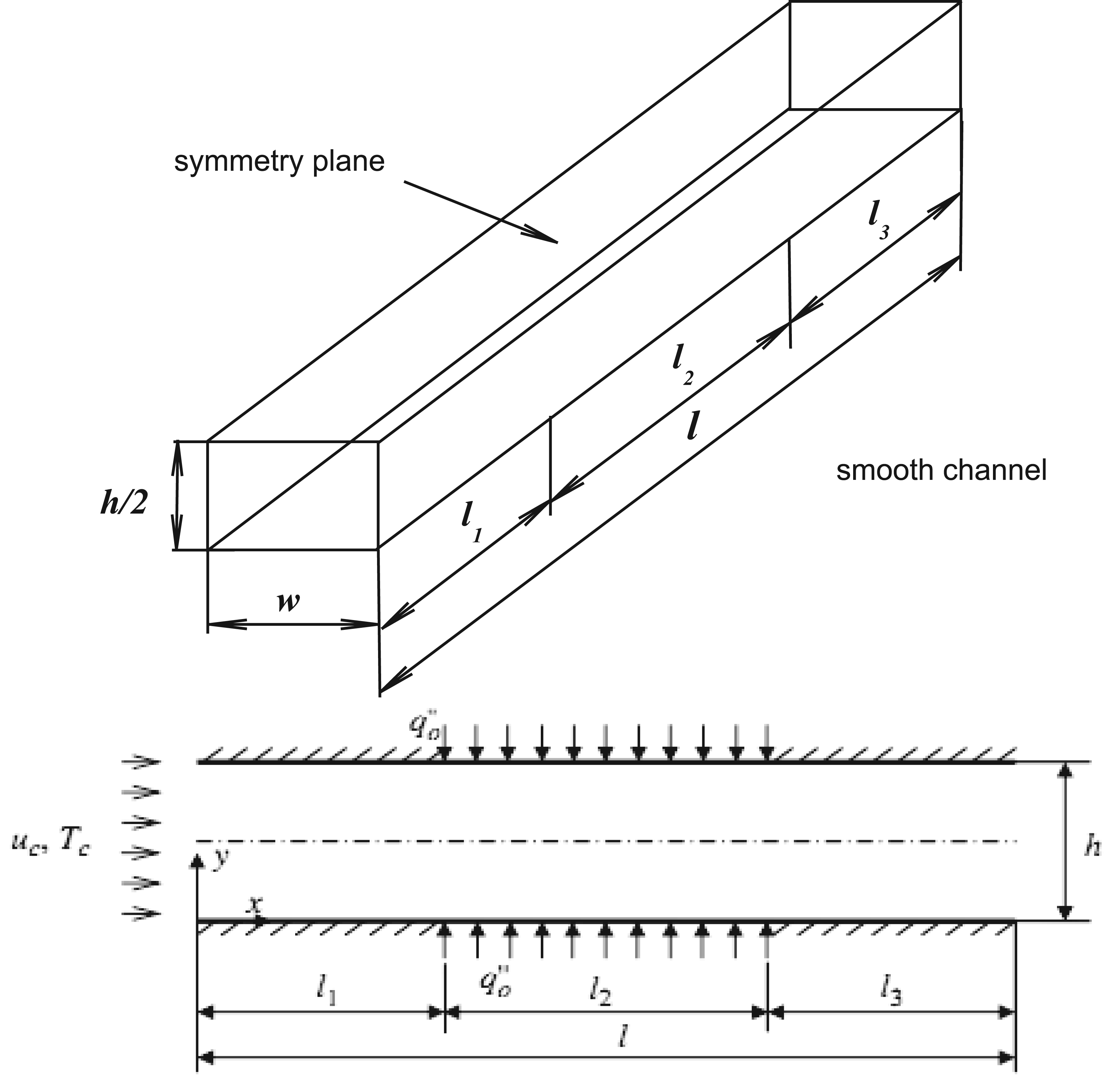
Three-dimensional and two-dimensional schematic of the investigated smooth microchannel.
Figure 1 shows the microchannel investigated in this study in terms of heat boundary conditions and entrance and exit length areas in two and three dimensions. The microchannel length is l = 2.5 mm and its height is h = 25 µm.
In Figure 2, the lengths are l 1 = l 3 = 750 µm and the microchannel width is w = 25 µm. The length is l 2 = 1000 µm. The investigated modes (a) and (b) are like Figure 1 in terms of boundary conditions in walls and general dimensions. The only distinction between modes (a) and (b) and the smooth channel is the position of ribs in l 2 area in upper and lower walls of the microchannel as in Figure 3.

The modes (a) and (b) as investigated in this study.

Investigating the position of ribs in l 2 area for the modes (a) and (b).
The temperature of the inlet fluid to the microchannel is Tc = 293 K. The flow in laminar mode is investigated for Reynolds numbers 10 and 100. Agent fluid is water and aluminum oxide powder (Al2O3) with a volume fraction of (φ = 0−0.04).
In this study, three-dimensional flow is assumed to be incompressible, Newtonian, laminar, and single-phased. In the entrance areas of the microchannel, fluid is entered with uniform velocity, and the shape of nanoparticles is assumed to be uniform and spherical.
Governing equations for laminar nanofluids
Governing dimensionless equations include equations of continuity, momentum, and energy, which are solved for permanent and laminar mode in Cartesian coordinates 14


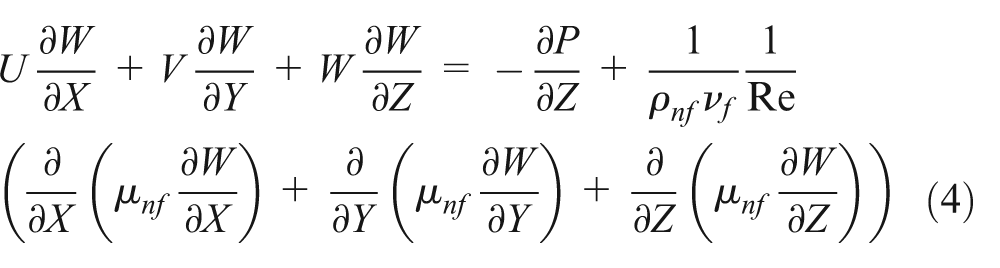
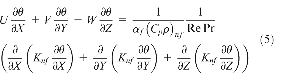
In the above equations, the following dimensionless parameters are used 14

In the above equation, X, Y, Z are the coordinates of the axes along the x, y, z, respectively. Also, parameters of U, V, W are the dimensionless velocities along the axes, x, y, z, respectively. Dh, θ, P, Pr, Re,
Nanofluid properties
Thermophysical properties of the nanofluid and aluminum powder nanoparticles are presented in Table 1. The following relationship is used for calculating nanofluid density15,16,17

Thermophysical properties of the nanofluid and solid nanoparticle. 17

In equation (7), parameters
Effective heat distribution coefficient of the nanofluid is calculated from the following formula 18

In the above equation, parameters
Specific heat capacity of the nanofluid is calculated by the following formula 19

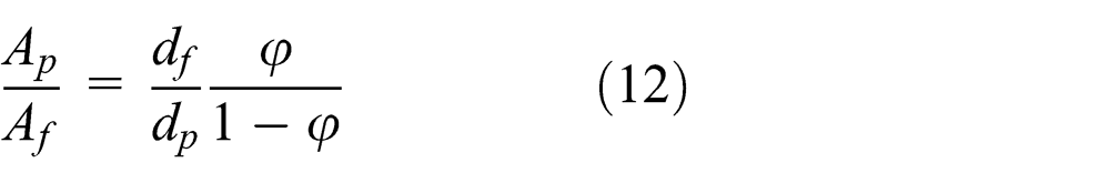
Brinkman relationship20,21 is used to calculate effective dynamic viscosity of nanofluid

In equation (10), expressions

where experimental constant is c = 36,000, and terms
where water molecule diameter equals df = 2 Ǻ, aluminum nanoparticle molecule diameter equals ds = 50 nm, and us value is Brownian motion velocity of nanoparticles and is calculated by the following formula

where κb = 1.3807 × 10⁻²³ J/K value is Boltzmann constant. 23
To calculate the local Nusselt number along the microchannel walls, the following equation is used, where the values of Tw
and Tm
are average temperature of the wall and bulk temperature of the fluid,
24
respectively, and
The following equation is used for calculate fanning friction factor 25

In equation (16),

In equation (17), A is the inlet cross-sectional area of microchannel. For general evaluation of heat–fluid performance of the rib-roughened microchannel, performance evaluation criterion (PEC) parameter is defined as heat efficiency as follows 31

In the definition of factor PEC, expressions

Numerical method
Equations governing laminar flow of the water–aluminum oxide nanofluid in three-dimensional and steady state mode are continuity, momentum, and energy equations. These equations are solved and discretized by finite-volume method. Semi-Implicit Method for Pressure Linked Equations—Consistent (SIMPLEC) algorithm is used to solve velocity–pressure coupled equations. The remainder of 10−6 is selected as the acceptable remainder to obtain exact answers and ignorable error from the current problem solving and using less computer memory in numerical simulation process maximum.
Numerical procedure validation
In the numerical solution of the current problem, the results from the numerical simulation were validated through the results of the reference 34 with identical geometric and boundary conditions to ensure the accuracy of the results. With regard to Figure 4, the average Nusselt number in this study is in good agreement with the study performed in the reference. 34 The average Nusselt number in smooth channel increases by increasing Reynolds number, which is due to better confounding of fluid layers as a result of an increase in velocity in higher Reynolds number, which in turn causes a decrease in heat gradient in-between the layers far from the hot surface of the microchannel. As nanoparticle volume fraction increases, the average Nusselt number increases as well due to the existence of solid nanoparticles in between fluid layers. Existence of nanoparticles improves heat conductivity properties of the fluid and reinforces heat transfer mechanisms in micron scale.

Validation of average Nusselt number in the smooth microchannel in different nanoparticle volume fractions through the reference. 34
Grid independence
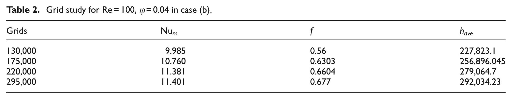
In the research ahead, to achieve optimal grid number, the effect number of grid will be investigated on the heat transfer and fluid flow parameters. The grid independence study of the present numerical simulation is shown in Table 2, which illustrates the results for Reynolds numbers of 100 and volume fractions of 4% in case (b) through average value of Nusselt number, friction factor variation, and convection heat transfer coefficient. The results indicate that for the grid number of 220,000, the average Nusselt number and friction factor variation and convection heat transfer coefficient have a maximum error of less than 5%. Furthermore, for this number of grids, compared to 295,000 grids, the computation time is reduced and the numerical error is negligible.
Grid study for Re = 100, φ = 0.04 in case (b).
Results and discussions
In this numerical study, laminar flow of the water–aluminum oxide nanofluid was investigated in a rectangular three-dimensional microchannel. This research studied the effect of ribs on dynamic behavior of the computational fluids of nanofluid in different modes of (a) and (b). The results embrace the average Nusselt number, average convection heat transfer coefficient, heat–fluid PEC, pumping power, friction factor, and Poiseuille number. These results were considered for two modes (a) and (b) and are presented as a function of nanoparticle volume fraction. Calculated values for each parameter in each mode of (a) and (b) are compared with similar parameters in the smooth microchannel with identical geometric and boundary (heat–fluid) conditions with pure water cooling fluid. The results of this study are calculated for Reynolds numbers of 10 and 100 and volume fractions of φ = 0%−4% aluminum nanoparticle. Figure 5 shows the friction factor diagram in the smooth microchannel. It is observed that friction factor in the smooth channel decreases by increasing Reynolds number. With regard to the figure, friction factor of the flow with Reynolds number of 10 is about 10 times as large as that with Reynolds number of 100 due to more fluid contact with microchannel surfaces in lower velocities. By increasing nanoparticle volume fraction, friction factor increases due to an increase in shear stress in walls as a result of the existence of solid particles in cooling fluid. The main reason should be that the dynamic viscosity increased very quickly as the nanoparticle volume fraction increased, so the flowability of nanofluid turned worse, which led to an increase in the thickness of boundary layer. As a result, the friction factor increased.
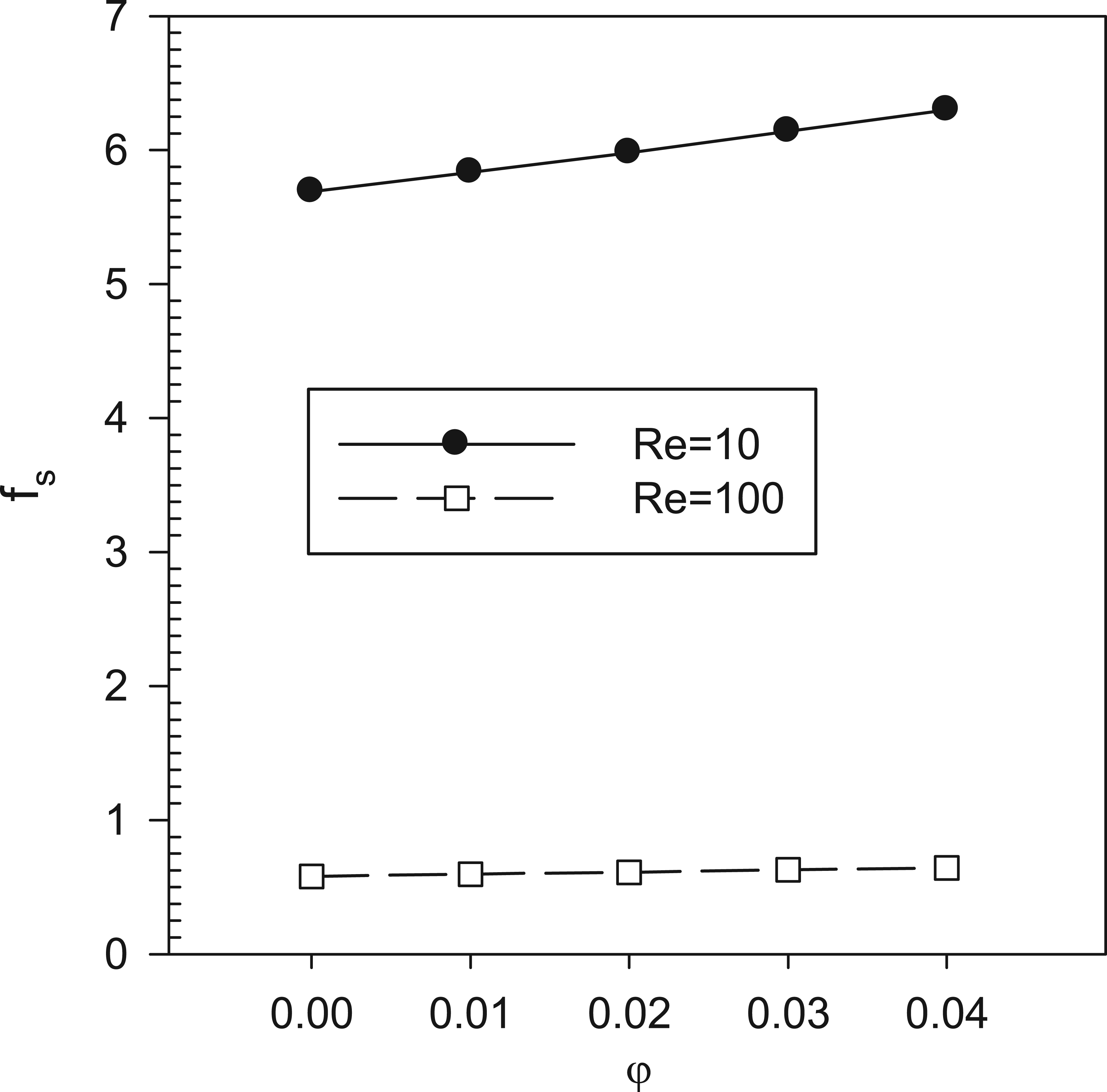
Friction factor diagram in the smooth microchannel in different nanoparticle volume fractions.
Figure 6 compares friction factor in each mode of (a) and (b) to the smooth microchannel. It is observed that due to the existence of the ribs, friction factor has been significantly increased. Friction factor in mode (a) is larger due to the pressure drop resulting from an increase in the number of ribs with higher heights compared to mode (b). In both modes, increasing nanoparticle volume fraction increases friction factor as well. In comparison to Reynolds numbers 10 and 100, in the case of (a), the coefficient of friction is increased, which causes a further drop in velocity in this case, and graphs in case (b) to have a higher level.

Friction factor ratio diagram in different nanoparticle volume fractions.
Figure 7 shows the value of average Nusselt numbers in each mode of (a) and (b) compared to the smooth microchannel. The average Nusselt number increases as Reynolds number and nanoparticle volume fraction increase. The average Nusselt number ratio in microchannel (a) has increased compared to mode (b) in each Reynolds number of 10 and 100, which is due to lower heat gradient in rib-roughened surfaces resulting from the existence of more ribs with higher heights. By putting a rib in the direction of fluid flow, a better mixing of the fluid layers happens, and better heat distribution between layers of the fluid is performed. With regard to Figure 7, the increase in heat transfer in comparison to smooth microchannels in both Reynolds numbers 10 and 100 is considerable.

The average Nusselt number ratio diagram in different nanoparticle volume fractions.
Figure 8 shows the average convection heat transfer coefficient in each mode of (a) and (b) compared to the smooth microchannel with identical conditions. Like the average Nusselt number, the value of this coefficient increases by an increase in Reynolds number and nanoparticle volume fraction in both modes. The increasing trend of this coefficient is larger in higher Reynolds and with higher nanoparticle volume fractions. Increase in heat transfer coefficient at Reynolds number 100, compared to Reynolds number 10, is considerably more. In case (a), when Reynolds number is 100 and the 4% volume fraction of nanoparticles, it is possible to achieve a heat transfer equivalent to 4.5 times as large as that in smooth microchannel.

The average convection heat transfer coefficient ratio diagram in different nanoparticle volume fractions.
Figure 9 shows the Poiseuille number ratio for the modes of (a) and (b) compared to the smooth channel. Due to the existence of ribs, Poiseuille number has increased in the rib-roughened microchannel. Ribs cause more contact surface of fluid and walls and create an obstruction in the microchannel, which has a large effect on pressure drop and causes an increase in Poiseuille number compared to the smooth channel. Increasing volume fraction of solid nanoparticles increases fluid viscosity, which in turn increases friction factor and Poiseuille number.

Poiseuille number ratio diagram in different nanoparticle volume fractions.
In Figure 10, pumping power ratio for each modes of (a) and (b) is compared to the smooth microchannel. It is observed that due to the existence of nanoparticles, the value of density and dynamic viscosity of the cooling fluid increases; and on the other hand, the existence of the ribs in the microchannel causes an obstruction, which increases the pumping power given the above-mentioned points. Increased flow rate in microchannels caused by an increase in the fluid inlet velocity requires a higher pumping power. For both cases (a) and (b), the pumping power diagram at Reynolds number 100, in comparison to the Reynolds number 10, is at a higher level.

Pumping power ratio diagram in different nanoparticle volume fractions.
In Figure 11, PEC of rib-roughened microchannels (a) and (b) evaluates the relation of heat transfer value to friction effects and compares both channels in relation to the smooth channel in identical conditions. By comparing the diagrams, it can be found that an increase in the number of ribs with higher heights causes higher efficiency of microchannel (a). This criterion increases by an increase in volume fraction for both modes of (a) and (b) which is due to higher effects of heat transfer compared to nanoparticle friction effects. In Reynolds number 10 for both cases, (a) and (b), diagram PEC, with an increase in volume fraction, the trend is the decreasing, which expresses a significant increase in the coefficient of friction against an increase in heat transfer. In Reynolds number 100, the behavior of diagram PEC is contrary to Reynolds number 10, and increase in heat transfer is significant. The diagram with increasing volume fraction is uptrend.

Performance evaluation criterion of microchannel diagram in different nanoparticle volume fractions.
Figures 12 and 13 evaluate local Nusselt number contours in the walls of microchannels (a) and (b) in volume fractions of φ = 0%−4% for Reynolds number 100. Figure 12(a) relates to mode (a) in Reynolds number 100 and pure water fluid. Figure 12(b) relates to mode (a) in Reynolds number 100 and volume fractions of 4% of the solid nanoparticle.

Local Nusselt number contours for the mode in Reynolds number 100 with volume fraction of (a) φ a = 0 and (b) φ b = 0.04.
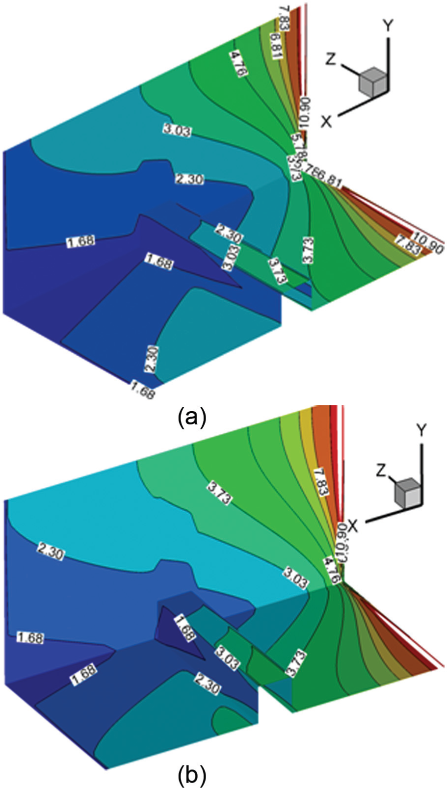
Local Nusselt number contours for the mode in Reynolds number 100 with volume fraction of (a) φ a = 0 and (b) φ b = 0.04.
Figure 13(a) relates to mode (b) in Reynolds number 100 and pure water fluid. Figure 13(b) relates to mode (b) in Reynolds number 100 and volume fraction of 4% of the solid nanoparticle. It is observed that in mode (a), due to the existence of more ribs, in each nanoparticle volume fraction, the areas with higher local Nusselt number and those with lower heat distribution gradient increase compared to the mode (b). In addition to the number of ribs and higher height of ribs, increase in nanoparticle volume fraction in each Figures 12(b) and 13(b) compared to Figures 12(a) and 13(a) causes better distribution of heat transfer in the microchannel.
Conclusion
In this study, heat transfer of laminar flow of water–aluminum oxide nanofluid was investigated in rib-roughened three-dimensional microchannel, and the results were compared with those from the smooth microchannel in identical geometric and boundary conditions. According to the results obtained in this study, it can be found that using ribs in microchannels causes an increase in heat transfer rate and a decrease in heat gradient in between layers of cooling fluid.
Existence of nanoparticles in the cooling fluid also has a significant effect on increasing heat transfer, which is reinforced with an increase in Reynolds number. However, on the other hand, existence of ribs in microchannel causes a pressure drop due to the obstruction compared to the smooth channel, which in turn causes an increase in friction factor and pumping power. Although using nanofluid causes an increase in heat transfer, existence of nanoparticles in the cooling fluid causes an increase in density and viscosity, which in turn increases shear rate in walls and friction factor and pumping power. Finally, efficiency of using ribs and nanofluid in the microchannel should be evaluated by PEC. Given the diagrams of Nusselt number ratio, a heat transfer of up to 4.5 times of the smooth channel can be obtained using nanofluid and ribs in the microchannel.
Footnotes
Appendix 1
Academic Editor: Oronzio Manca
Declaration of conflicting interests
The author(s) declared no potential conflicts of interest with respect to the research, authorship, and/or publication of this article.
Funding
The author(s) received no financial support for the research, authorship, and/or publication of this article.