
Abstract
Regarding the design optimization of the heat exchanger, the traditional method of changing the size of the macroscopic structure can no longer meet the increasing demand for heat exchange performance. The superhydrophobic surface can significantly reduce the flow resistance, which is expected to be a new method for the optimal design of heat exchanger. However, when the superhydrophobic effect is applied to a specific type of heat exchanger, its flow and heat transfer performance is not clear. In this paper, the flow and heat transfer model of the traversing superhydrophobic tube bundle is studied. Combined with the FLUENT 18.0 software, the slip boundary conditions of the superhydrophobic surface are deduced, and the flow and heat transfer characteristics of the superhydrophobic tube bundle surface and the wake are numerically analyzed, the influence mechanisms of slip effect on flow and heat transfer characteristics were obtained. Overall, as Ls increases, the comprehensive Nu, also known as heat transfer performance, on the cylindrical surface gradually increases, while the comprehensive Cf, also known as frictional resistance, on the cylindrical surface gradually decreases, indicating that superhydrophobic performance is expected to achieve heat transfer enhancement. The above conclusions can provide a theoretical basis for the optimal design of high-efficiency compact heat exchanger, and have important engineering application significance.
Introduction
Heat exchangers are commonly used in the aerospace, mechanical, chemical, electronics and other industries to recover and transfer heat. For example, in aerospace, heat exchangers are used to control the temperature inside aircraft to ensure that the aircraft operates properly in high or low temperature environments. In mechanical engineering, for example, heat exchangers are used to cool engines, lubricating oils and other critical components to ensure the efficient operation and long service life of machines. With the advancement of science and technology, power system integration has gotten more and more advanced, which has resulted in the shrinking of heat exchanger 1 and a smaller overall structure volume. Meanwhile the heat exchanger’s surface area is also decreasing, and in order to meet application requirements, the heat exchanger’s efficiency must be further increased in accordance with the convective heat transfer principle. As a result, the primary development trend is toward high-efficiency-compact heat exchanger.
The traditional method of designing efficient and compact heat exchangers is to change their structure and size from a macro perspective, but gradually bottlenecks have emerged. Many studies, from a micro perspective, such as using nanoparticle fluids2,3 and material surface modification methods, have become new methods for achieving efficient and compact heat exchangers. It is worthy note that the superhydrophobic surface 4 can cause the slip to reduce the flow resistance. Developing the superhydrophobic surface is hopeful to realize the high-efficiency-compact heat exchanger.5,6
The characteristics of drag reduction on the superhydrophobic surface are the subject of much investigation by domestic and international academics.7,8 Lv and Zhang 9 conducted experimentally superhydrophobic surface flow in turbulent state and measured the slip length for various tube diameter and Reynolds number. They examined how slip length affected flow and heat transfer characteristics and discovered that the maximum flow loss was 17.8%. Using lattice Boltz method, Rastegari and Akhavan 10 studied the drag reduction in the turbulent pipeline with longitudinal micro-grooves. They analyzed how interface salient angle affected drag reduction and found that the maximum drag reduction efficiency was 61%. Huang et al. 11 studied numerically how the slip length affected differential pressure of flow around a circle cylinder in a laminar state. They found that the super hydrophobicity can be used to manage the flow separation, vortex motion, and flow drag reduction.
For the study of heat exchanger, in addition to the flow characteristics, heat transfer performance is also the focus of many scholars.12–16 When the slip phenomenon occurs on a superhydrophobic surface, the closest thing to the solid surface is a layer of air film. Since the dynamic viscosity of air is lower than that of the liquid in this layer of air film, there are discontinuities in the heat transfer of the solid-liquid interface, which results in temperature jumps, increases the thermal resistance of the surface, and deteriorates heat transfer. 9 However, some scholars have pointed out that the heat transfer of superhydrophobic surfaces is a contradiction between convective heat transfer and heat conduction. The surface film increases thermal resistance, but the slippage of the interface enhances the surface convective heat transport ability. 6 Even the research findings of numerous academics support the latter conclusion.17,18 Additionally, it has been noted that the action of the slip velocity causes the air within the film to experience vortex flow, improving heat transfer. 19 Wei et al. 20 numerically investigated the flow in micro-cavities at low Reynolds number. The effect of the forked row arrangement of the recesses on the flow drag reduction and heat transfer enhancement was investigated, and it was noted that the flow in the free shear surface of the recesses increased the slip length of the superhydrophobic surface and enhanced the total thermal efficiency of the cavity channel.
However, although superhydrophobic properties have a certain flow drag reduction effect when used for in-pipe flow, and can even achieve some capability of heat transfer enhancement by changing the microstructure of the superhydrophobic surface, when superhydrophobic properties are used outside the pipe, the flow drag reduction and heat transfer enhancement properties are not solved due to phenomena such as flow separation and vortex shedding on the pipe surface. 21 In addition, since in some heat exchanger it is more important to design heat transfer enhancement performance outside the pipe, that is, low flow resistance and high heat transfer efficiency, the flow and heat transfer characteristics outside the pipe have more important scientific and engineering significance for heat exchanger development.
The above-mentioned studies focus on the superhydrophobic plane and the inside of the pipe, and less on the outside of the superhydrophobic pipe. The flow outside the pipe contains rich flow phenomena such as flow separation and flow reattachment. In particular, the slip effect will redistribute flow separation and reattachment, which will change the flow and heat transfer characteristics and affect the heat transfer enhancement performance. Therefore, it is important to reveal the heat transfer enhancement mechanism outside the superhydrophobic tube bundle as an important theoretical support for the design optimization of superhydrophobic heat exchanger.
The traditional design optimization of heat exchangers is based on the geometric structure, which is considered from a macro perspective. The use of superhydrophobic performance to achieve heat transfer enhancement of heat exchangers is considered from a material science perspective, and the overall design is from a micro perspective. Compared to this, studying the impact of superhydrophobic performance on heat transfer enhancement of tube bundles is more innovative. This article focuses on typical scenarios of efficient compact heat exchanger flow, namely transitional and laminar flow state, specifically studying the comprehensive heat transfer and flow performance of tube bundles, surface flow and heat transfer characteristics, flow separation characteristics, wake mixing characteristics, etc. These studies are expected to fill the gaps in the theory of high-efficiency compact heat exchanger design and provide new theoretical basis and practical guidance for the development of related fields.
Numerical methods
This article is based on ANSYS 18.0 software and uses the finite volume method, combined with slip boundary conditions, to calculate the continuity equation, momentum equation, and energy equation. For the slip boundary, since the calculation of the ANSYS software adopts the Cartesian coordinate system, it is necessary to convert the coordinates near the cylinder surface into the Cartesian coordinate system. Therefore, the mathematical expression of UDF is obtained through deduction. The above method is simple in modeling and accurate in calculation, and is especially suitable for numerical analysis of flow and heat transfer characteristics of superhydrophobic cylinder surface.
Governing equations
Considering that the size of the heat exchanger tube bundle is gradually miniaturized, the flow will change from turbulent flow to transitional flow or even laminar flow, and its flow and heat transfer behavior is two-dimensional. A two-dimensional numerical model of flow and heat transfer for cross-swept single cylinder with a Re range of 70∼180 was established. The numerical model is based on the following assumptions: the fluid is an incompressible Newtonian fluid; the flow is a two-dimensional flow; the fluid properties are constant. The governing equations include continuity equation, momentum equations, and energy equation, 22 as follows:

Where U, V, P, and T are the variables to be solved for, being the velocity components in the x and y directions, pressure and temperature respectively. h, ρ, μ, λ, and CP represent the enthalpy, density, coefficient of viscosity, thermal conductivity, and specific heat at constant pressure of the fluid, respectively.
Physical model and boundary conditions
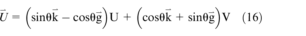
The calculation area of the research object is shown in Figure 1. The coordinate system is composed of X, Y, and O which represent the flow direction and origin respectively. The center of the cylinder is at the origin and the diameter is D (0.008 m). The boundary of the calculation area constitutes a rectangle. The left and right boundaries are the inlet and outlet, respectively, and the positions are at −5D and 20D, respectively. The upper and lower boundaries are solid walls, and the positions are at ±5D respectively.
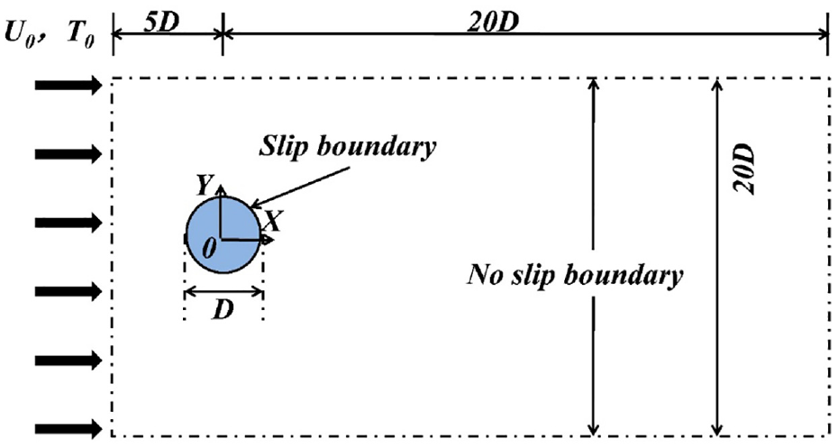
Two-dimensional single cylinder calculation area.
With regard to the setting of boundary conditions, uniform velocity and temperature conditions are used for the inlet (equation (5)). No-slip and inlet temperature conditions are used for the solid wall (equation (6)). Pressure outlet conditions are used for the outlet (equation (7)). Slip boundary and isothermal heating conditions are used for the cylindrical surface (equation (8)). Their mathematical forms are shown in the following formulas respectively


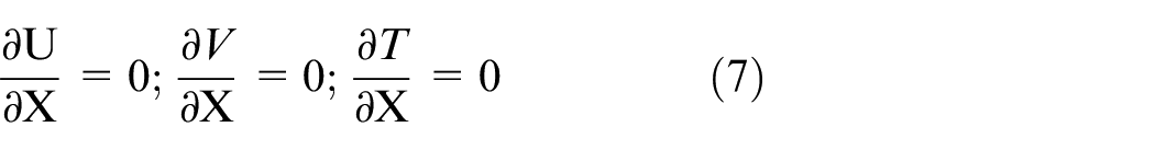
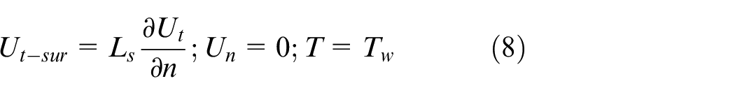
U 0 depends on Re, T0 is set to 300K, and Tw is set to 340K. Ut represents the tangential velocity of the cylindrical surface, and Un represents the normal velocity of the cylindrical surface.
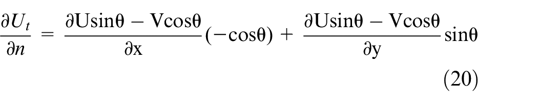
Slip boundary expression
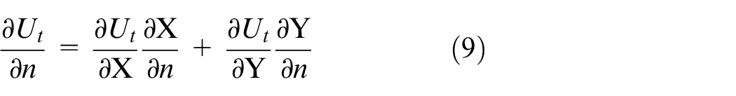
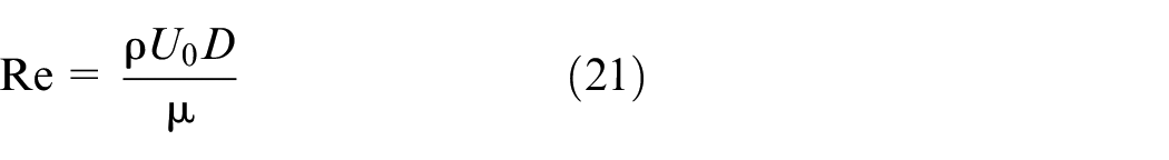
The numerical calculations were performed using ANSYS-Fluent 18.0 software. The time-space parameter expressions during the solution process were based on a Cartesian coordinate system, which could not directly describe the velocity gradient (∂Ut/∂n) on the cylindrical surface. It was necessary to convert the cylindrical coordinates into rectangular coordinates (as illustrated in Figure 2) and derive a suitable solver form of ∂Ut/∂n expression. And then ∂Ut/∂n was implemented by the UDF function. The target parameter ∂Ut/∂n can be expressed in the following form.
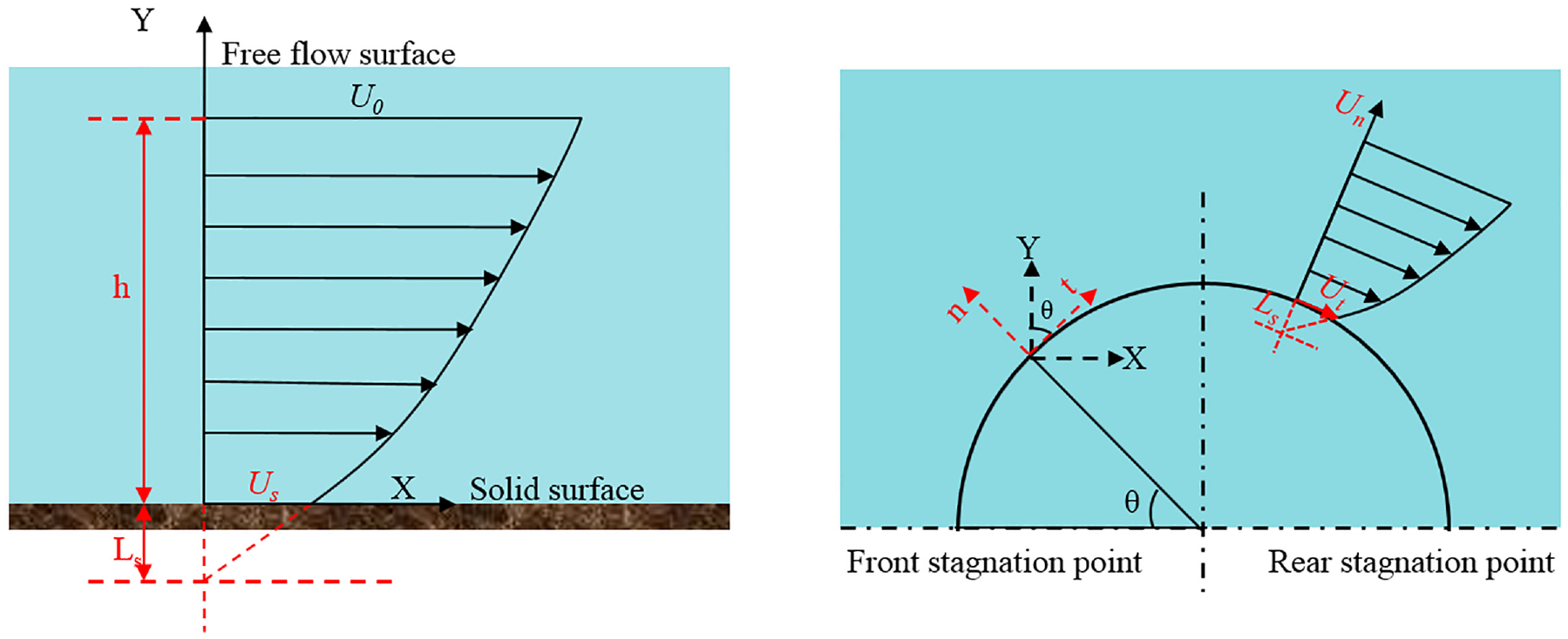
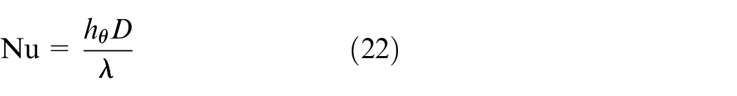
Schematic diagram of slip velocity boundary model for superhydrophobic plane and cylindrical surface.
The target parameters can be expressed through the mathematical derivation of ∂Ut/∂X, ∂Ut/∂Y, ∂X/∂n,Y/∂n.
Firstly, the Cartesian coordinate system can be expressed in terms of a columnar coordinate system as follows.
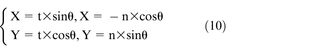
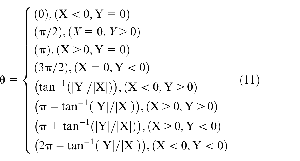
Where t is the tangential unit displacement and n is the normal unit displacement. θ is the angle between the two coordinate systems and can be expressed by the following equation.
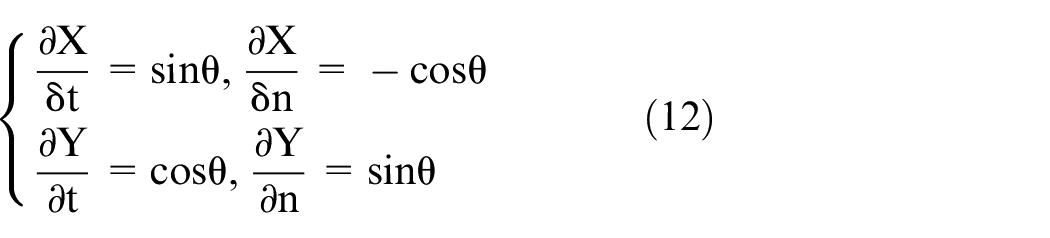
Taking the derivative in the direction of t and n for X and Y, we can get:
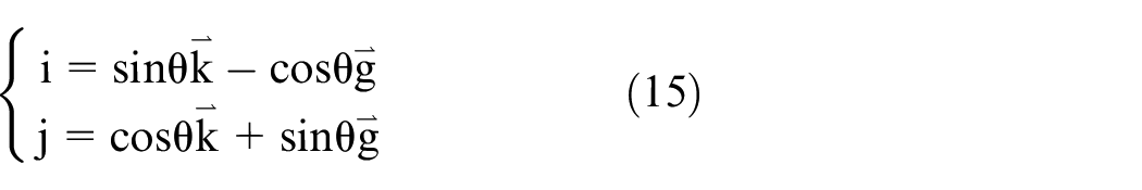
The velocity vector


where (
The expression for
Expressed by (

The expressions of Ut and Un can be obtained:


Finally, we can get:
According to the above equations, the velocity gradient (∂Ut/∂n) can be expressed in combination with the relevant macros in Fluent.
Numerical methodology
The calculations were performed using ANSYS FLUENT 18.0 software, and the pressure, velocity and temperature information of the flow field was calculated by solving the control equations and boundary conditions. The Least Squares Cell-Based Gradient is used. The second-order upwind scheme is used for momentum and energy, and the second order scheme is adopted for pressure. The discretized equations are solved using the ADI algorithm. For the treatment of the slip boundary, the UDF formulation is used. The moving wall boundary condition is used in the cylindrical surface condition, and then the form of the component is chosen to define the slip velocity in the X and Y directions respectively. In order to avoid the calculation divergence, a no-slip boundary condition is firstly applied to the cylinder, the slip boundary condition is later brought in when the calculation is relatively stable. The residuals for each parameter are set to 1e−06 and calculated until convergence.
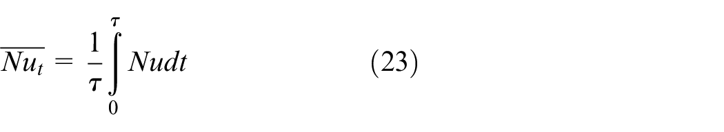
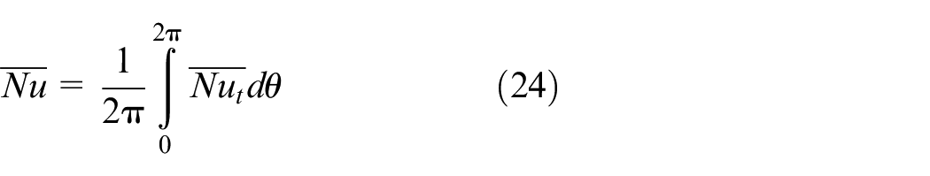
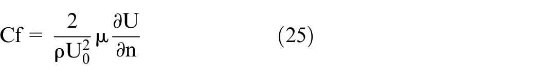
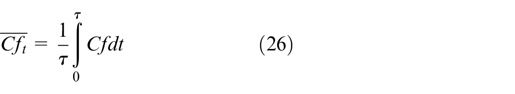
Definition of parameters
The following dimensionless parameters will appear in the Results and Discussion section of the paper, and they are defined as follows.
Validation of results
Grid independence verification
In order to eliminate the impact of the number of grids on the calculation results, grid independence verification will be carried out in the following paper. The number of grids, which is an important part of grid quality, needs to be determined scientifically. Generally speaking, the larger the number of grids, the more accurate the calculation results. However, in view of the efficiency of the calculation, a reasonable number of grids needs to be chosen to ensure the efficiency of the calculation and the accuracy of the results. Therefore, it is necessary to verify the independence of the number of grids.
Based on ANSYS ICEM meshing software, a structured grid was used to discretize the physical field, which was divided into nine regions (G1, G2, G3, G4, G5, G6, G7, G8, and G9). The region around the cylinder (G5) was meshed with an O-grid, that is, a cylindrical coordinate system, which can accurately and effectively express the normal parameters of the cylindrical surface (as shown in Figure 3). When dividing the grid of each region, the length of the boundary grid is set to half of the adjacent grid. Especially the O-grid around the cylinder and the grid of the wake region are encrypted. This is because of the relatively complex changes in the temperature field of the flow field in this region, which can produce flow separation and wake flow instability and so on.
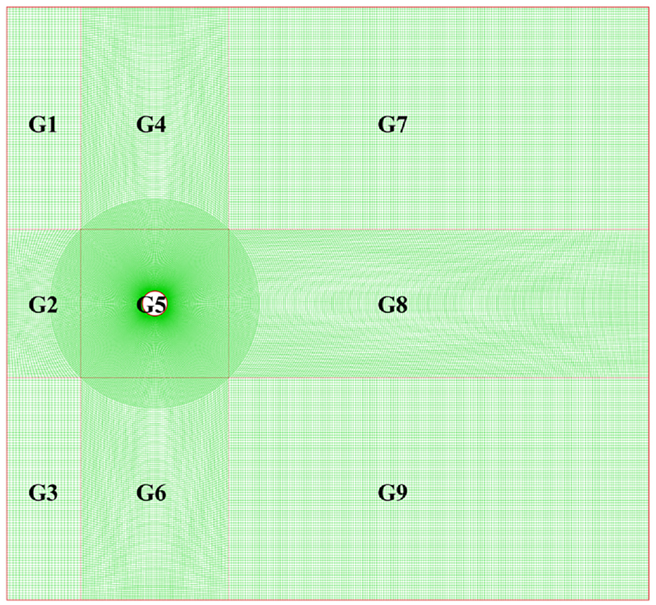
Meshing of single cylinder calculation area.
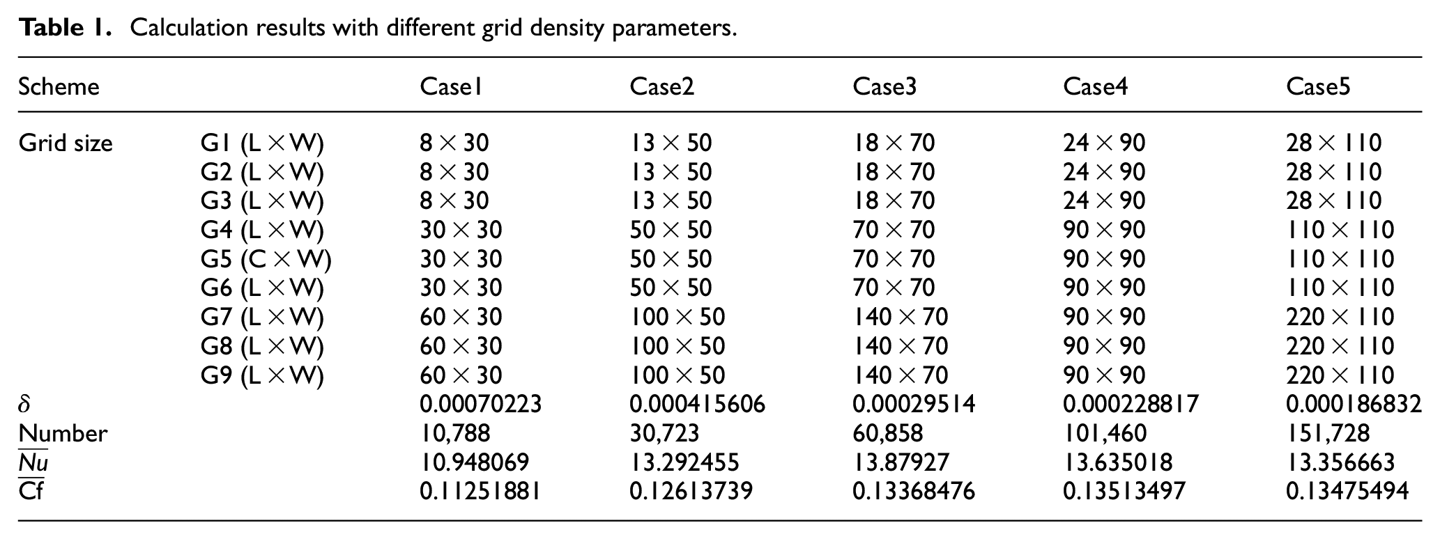
Based on the aforementioned meshing technique for Re = 120, Table 1 displays five instances of various grid numbers. The grid numbers are described by the number of length and width directions in nine regions, and the minimum and maximum grid number are 10,788 and 151,728, respectively. Considering that the main content of this research is the flow and heat transfer characteristics of the cylindrical surface, the time-space average Nusselt number (
Calculation results with different grid density parameters.
Validation of calculation results
Although the grid independence of the above computational model is verified, the results generated by its corresponding computational method remain to be verified. Based on the above mesh number (Case4), the computational analysis of the cylindrical flow heat transfer for Re = 120 with air as the medium was carried out. The time-averaged Nusser number (
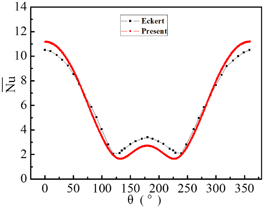
Verification of single cylinder calculation results.
Results and discussion
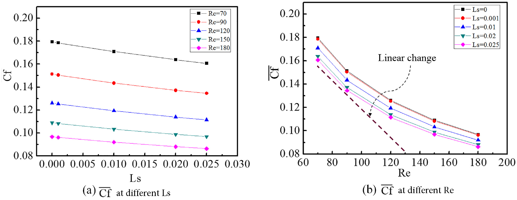
Effect of Re and Ls on the average
and
The velocity slip boundary model is employed in this study, and the slip feature will accelerate the cylindrical surface flow, affect the flow separation and wake stability, and significantly alter the heat transfer characteristics of the cylindrical surface. By computing the flow and heat transfer cases of Ls = 0, 0.001, 0.01, 0.02, 0.025 and Re = 70, 90, 120, 150, 180, and this study carefully analyzes the effect of Ls and Re on the cylindrical surface
The impacts of Ls and Re on the cylindrical surface
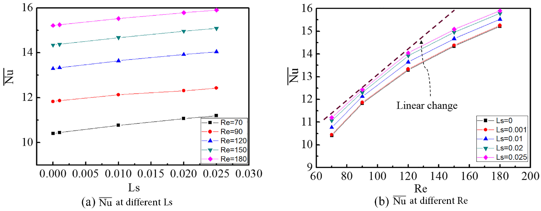
The effect of Re on
As another important parameter to study the heat transfer enhancement performance is the coefficient of friction (
Effect of Ls on
,
, and
at Re = 120
Considering that
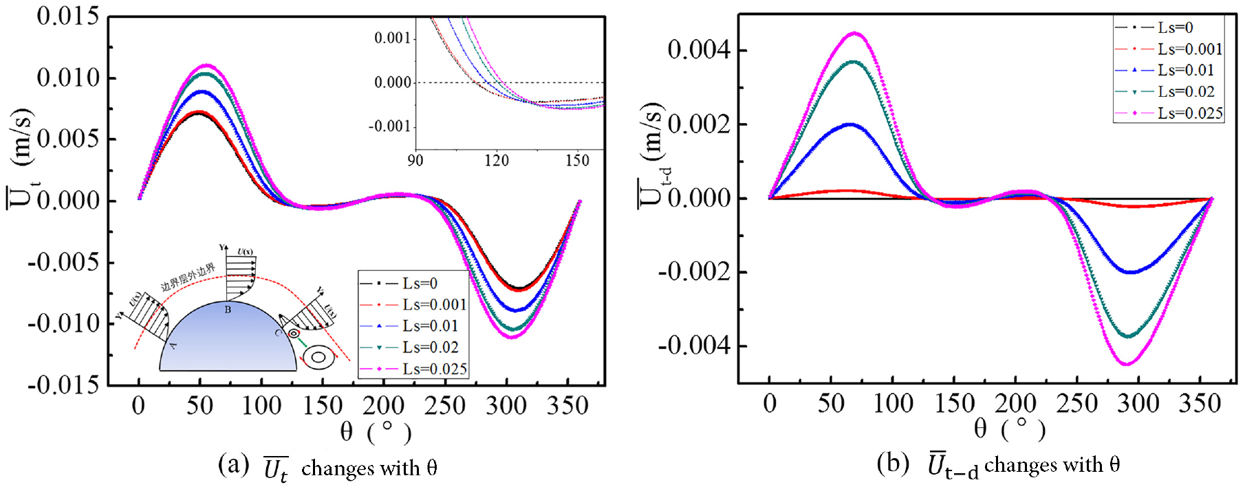
Ls has a significant effect on this process. An obvious rule is that the maximum
An enlarged view is shown in the upper right panel in Figure 7(a), where the black dotted line represents
In order to more clearly illustrate the contribution of Ls to the change of
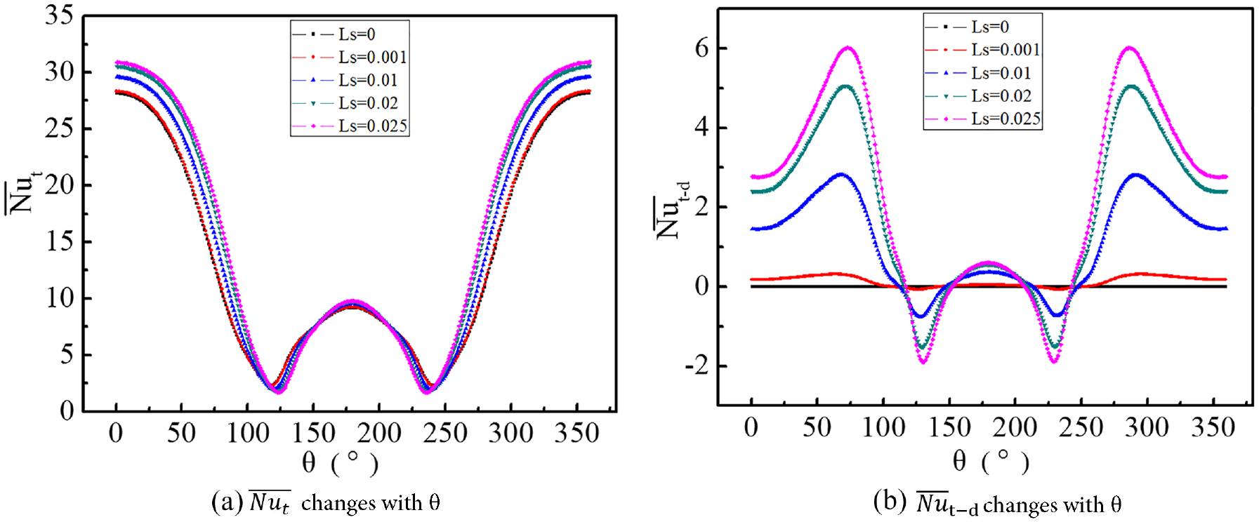
Ls has a significant effect on
The superhydrophobic slip effect also has an important effect on the friction coefficient of the cylindrical surface. Figure 9 shows the effect of Ls on the distribution of the time-averaged friction coefficient
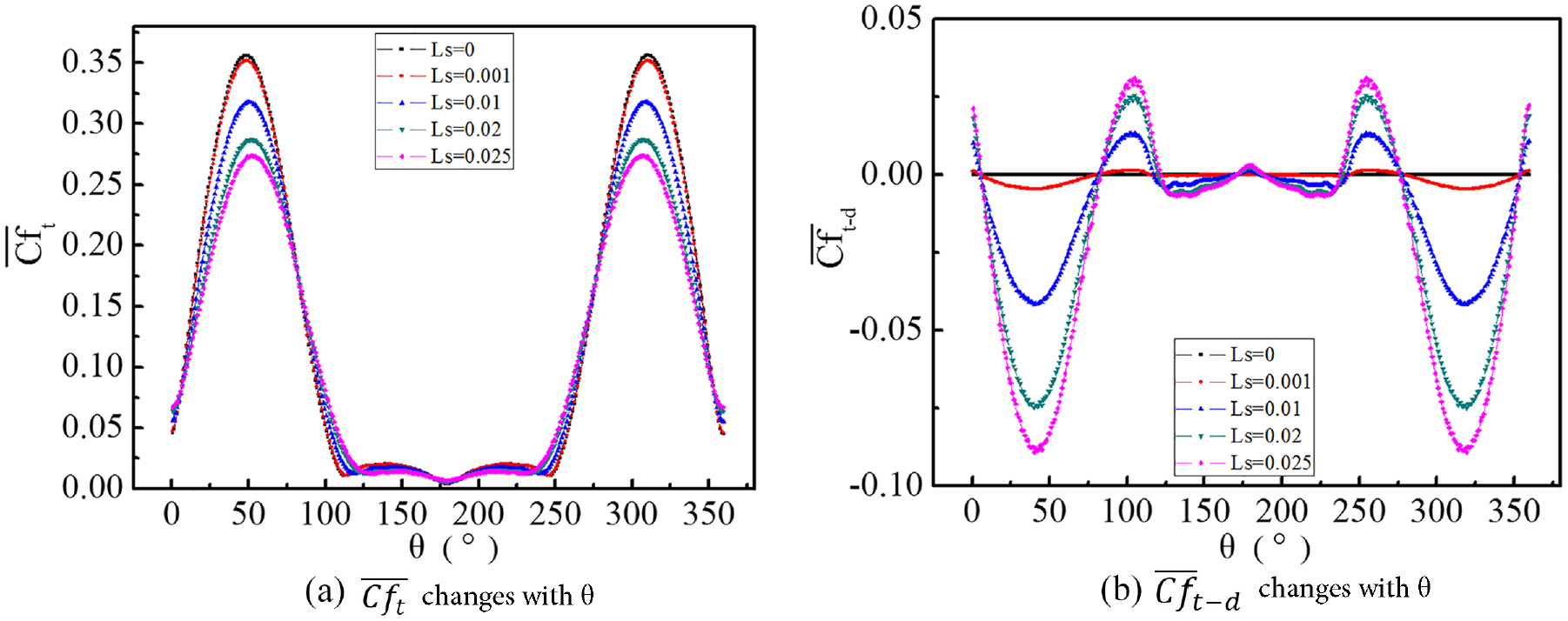
Ls also has a significant effect on
It can be found that in the region of 0 < θ < 80°, the contribution of
Effect of Ls on the cylindrical wake at Re = 120
The superhydrophobic slip effect changes the flow separation and affects the wake flow and heat transfer characteristics. Figure 10 shows the effect of Ls on the vorticity at various cross-sections of the cylindrical wake for Re = 120. The selected cross-sections include X/D = 2, 4, and 6. It can be found that the absolute value of the vorticity at the cross-section decreases as the cross-section moves backward. This is because the cylindrical surface generates strong vorticity, which gradually dissipates and starts to become less strong as the position is moved back. The expression of the wake vortex is in the form of wake bubbles (as shown in Figure 10), which guide the clockwise or counterclockwise low-speed motion. This can gradually introduce the cold fluid in the main stream to the center region of the wake, forming a mixture with the hot fluid after the separation. With the increase of Ls, the change of vorticity in X/D = 2 and 4 cross-section is less obvious, and the maximum vorticity in X/D = 6 cross-section gradually increases. This indicates that the slip effect delays the recession of the vortex. This is similar to Seo and Song’s 25 results, both mentioning that the slip factor will affect the wake vortex and change the size of the wake bubble. In addition, the position of the maximum vortex in the cross-section gradually moves toward the Y = 0 position, indicating that the slip effect affects the morphology of the wake bubble.
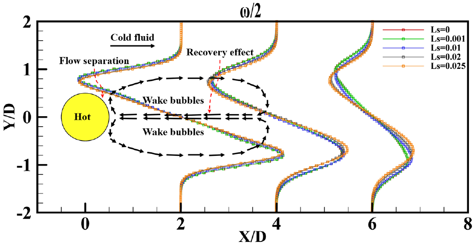
Different cross-sectional vorticity of cylindrical wake motion at different Ls for Re=120.
The wake flow characteristics will also affect the temperature distribution. Figure 11 shows the effects of Ls on the temperature of different cross-sections for the cylindrical wake at Re = 120 (for the cross-section locations, X/D = 2, 4, and 6 are also chosen). From the figure, it can be observed that when X/D = 2, the shape of the temperature distribution cross-section has a right-turned “M” shape, with a concave feature in the region of −0.8 < Y/D < 0.8. This is because the region is still in the wake bubble region, the flow is low velocity viscous flow, which can introduce the mainstream cold fluid into the region, resulting in depression. As the cross-section position moves back, the depression feature gradually disappears and gradually changes to a single-peak form, a process called the temperature recovery effect. The temperature recovery effect gradually decreases as the cross-section position moves backward. With the increase of Ls, the temperature gradually increases at the same cross-section near Y = 0. The main reason is that the surface slip weakens the temperature reversion effect of the wake, that is, it enhances the momentum in the X direction and weakens the momentum in the Y direction, thus weakening the energy of the return flow.
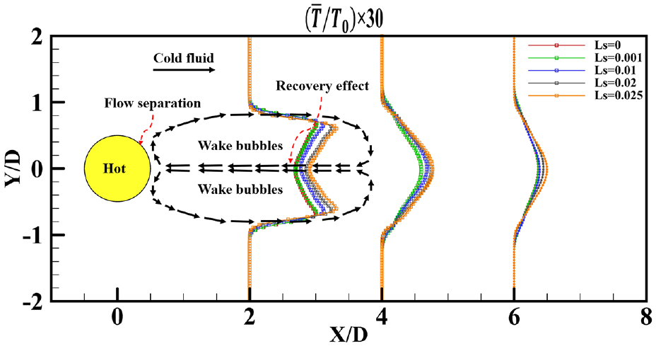
Different cross-sectional temperature of cylindrical wake motion at different Ls for Re=120.
Conclusion
Aiming at the unclear influence of superhydrophobic tube bundle slip effect on surface flow and heat transfer characteristics, this paper used ANSYS-Fluent 18.0 software to solve pressure, velocity and temperature information according to the governing equations and superhydrophobic boundary conditions. For superhydrophobic boundary processing, the cylindrical coordinate system is transformed into a rectangular coordinate system, and the slip boundary condition expression suitable for the solver form is deduced. Combined with the calculation results, the grid independence and the accuracy of the results are verified. The effects of Ls and Re on the cylindrical surface
As Re increases,
As Re increases,
As Ls increases,
As Ls increases, the position of the separation point gradually moves backward.
As Ls increases, the
As Ls increases,
As Ls increases, the vorticity gradually declines, the width of the wake bubble gradually decreases, and the temperature recovery effect in the wake gradually weakens.
Footnotes
Appendix
Declaration of conflicting interests
The author(s) declared no potential conflicts of interest with respect to the research, authorship, and/or publication of this article.
Funding
The author(s) disclosed receipt of the following financial support for the research, authorship, and/or publication of this article: This research work is supported by the “Natural Science Research of Higher Education Institutions of Jiangsu Province” (No.20KJB470010), “Changzhou Basic Research Program” (No. CJ20220033) and “Jiangsu Key Laboratory of Green Process Equipment.”
Data availability statement
The data that support the findings will be available.