
Abstract
This article looks into the mechanism of the driving torque ripple before and after shift, and the analyses are based on profound study of the structure and shift process of two-speed automated mechanical transmissions for pure electric vehicles. With the basic driving control strategy for pure electric vehicles, a torque compensation strategy in the shift process is proposed to suppress the ripple. Besides, theoretical analyses and simulations are conducted. The results show that by means of the proposed torque compensation strategy, the ripple is significantly abated and the shift cycle is eliminated.
Keywords
Introduction
Compared to the automated mechanical transmissions (AMTs) for traditional vehicles, the two-speed AMTs for pure electric vehicles have fewer gears, simpler structure, and higher efficiency.1,2 However, they also present some disadvantages due to the large rate of adjacent gears’ ratio. One such disadvantage is the driving torque ripple before and after shift, which does severe harm to driving comfort and vehicle dynamic performance. In addition, the AMT will shift up and down consecutively and frequently between two adjacent gears (this phenomenon is called shift cycle) especially when the vehicle runs on a slope.
Recently, the transmissions for pure electric vehicles have become a research focus. Ren et al. 3 studied pure electric vehicles equipped with fixed ratio transmission, multi-shift AMT, or continuously variable transmission. Their work shows that when a two-speed AMT is used, the energy consumption can be reduced by 9.2% over New European Driving Cycle (NEDC) cycle, and the size of the drivetrain is also decreased. Qin et al. 4 proposed a drivetrain containing an induction motor and a two-speed AMT. The simulation and test results indicate that the energy consumption is decreased by 6.6% and the driving range is extended by 7.1%. Fu et al. 5 presented a novel motor control strategy for an electric bus equipped with multi-gearbox and motor. The simulation results show that the control schedule leads to a short shift time. Gao et al. 6 investigated the appropriate traction motor for the military vehicle propulsion. They analyzed many aspects the motor driving characteristics could affect, such as the vehicle performance, structure complexity, and reliability. Hofman and Dai 7 looked into the elements that influence the energy efficiency of pure electric vehicles, including the transmission type, shift strategy, transmission efficiency, and final drive ratio. Wang et al. 8 proposed a control strategy that lowers the axially movable speed of the synchronizer to avoid shift impact. However, the shift time is compromised. Chen et al. 9 proposed a control strategy, and the vehicle test verifies that shift quality can be improved by selecting appropriate target motor speed based on target gear position. Huang et al. 10 focused on the shift control strategy for two-speed AMT on pure electric vehicles. Their research reveals that by means of motor active synchronizing, the power interrupt time can be decreased and the shift quality can be improved. Hu et al. 11 proposed a coordination matching control strategy in which the hybrid control unit participates in the shift process, in order to tackle the problem of coordination control of driving motor.
Previous studies3–7 mainly focused on the effect of transmission and motor on the vehicle performance, structure, and cost. But the mechanism of the driving torque ripple before and after shift is not taken into account yet. Other works8–11 primarily studied the shift impact and shift time in the shift process. However, a very few number of gears (compared to AMT for conventional vehicles) worsen driving comfort and vehicle dynamic performance, and the shift cycle is not taken into consideration.
In view of the above shortcomings in the existing works, in this article, the mechanism of the driving torque ripple before and after shift for the two-speed AMT is studied, and a torque compensation strategy for shift process is proposed.
The rest of the article is organized as follows. Section “Structure and shift process of the two-speed AMT for pure electric vehicles” provides detailed information of the structure and shift process of the two-speed AMT for pure electric vehicles. The mechanism of the driving force ripple before and after shift under two types of shift schedule is analyzed in section “Mechanism analysis of the driving force ripple before and after shift”. Then, a torque compensation strategy is proposed in section “Torque compensation strategy”. The simulation studies are presented in section “Simulation studies”. Finally, the conclusion of this work is provided in section “Conclusion”.
Structure and shift process of the two-speed AMT for pure electric vehicles
The powertrain layout of a pure electric vehicle equipped with the two-speed AMT is shown in Figure 1. The parameters of the powertrain are given in Table 1. The driving motor is directly connected to the transmission by a spline instead of a traditional clutch. The whole structure consists of the driving motor, AMT, final drive, and differential. This structure is a compact assembly, which helps to save space and reduce cost.

AMT powertrain system for pure electric vehicles.
Powertrain parameters.

AMT: automated mechanical transmission.
The flowchart of the shift process is shown in Figure 2. The shift process has five steps: torque interruption, disengagement of current gear, speed synchronization, engagement of target gear, and torque recovery. The detailed gearshift process and the relevant shifting control strategy have been studied by Hu et al. 11

Shift process flowchart.
Mechanism analysis of the driving force ripple before and after shift
Analysis of driving characteristics for pure electric vehicles
The driving motor produces a constant torque in low-speed range and a constant power in high-speed range. 12 To keep the continuity of wheel driving force, the driving motor and the transmission should be matched properly. That is to say, there should be at least one intersection point on the driving force envelope curve of the first gear and second gear. Thus, a smooth transition can be realized. Besides, the area under the vehicle speed envelope curve is called the driving characteristics field of pure electric vehicles, as shown in Figure 3. Note that ue1 and ue2 are the vehicle speeds corresponding to the driving motor nominal speed in the first gear and second gear, respectively, and u1 is the shift speed.

Driving characteristic with a shifting vehicle speed less than
In the results shown in Figure 3, when the pure electric vehicle drives at a constant opening of accelerator pedal, if u1 > ue2, the driving force remains the same after shift; if u1 < ue2, the driving force changes from point A to point B in the upshift process as the vehicle speed reaches u1. At the moment, the driving force greatly decreases, which does harm to driving comfort and vehicle dynamic performance. As seen in Figure 3, the driving force changes along the direction BC. Thus, the area ABC cannot be fully utilized unless a proper shift schedule is employed. In the following text, the effect of different shift schedules on the driving force ripple will be studied, with the basic driving control strategy adopted.
Basic driving control strategy for pure electric vehicles
Currently, three types of relationships between the accelerator opening and the motor driving torque are commonly used, as shown in Figure 4. The first one, normally called soft strategy, can lead to poor acceleration performance during vehicle starting and this is often dangerous in heavy traffic as it would give the driver a feeling of being vulnerable, but good driving comfort in smooth traffic. The second one, which is simply a linear relationship, leads to better acceleration performance. The third one, normally named hard strategy, can achieve good acceleration ability. In this article, the second one is adopted in order to satisfy the requirement for handling and acceleration performance.

Relationship between accelerator pedal opening and motor driving torque.
To better meet the driver’s intention, the principle of the torque calibration corresponding to the accelerator pedal opening is as follows: with a constant motor speed, the motor torque becomes larger as the accelerator pedal opening increases. When the accelerator pedal position remains the same, the higher the motor speed is, the smaller the motor torque should be. Based on this torque calibration principle, the basic driving control strategy for pure electric vehicles is proposed, as shown in Figure 5.

Relationship between motor torque and motor speed at different accelerator pedal openings.
Effect of the shift schedule on the driving force ripple
The driving force ripple coefficient is defined in equation (1), in order to analyze the effect of the shift schedule on the driving force ripple before and after shift:

where Faft is the driving force after shift, and Fbef is the driving force before shift.
In essence, λ shows the driving force range before and after shift, and the larger the absolute value of λ is, the more severely the driving force ripple happens, according to the equation (1). Ideally, the value of λ should be kept at zero, in order to guarantee driving comfort and vehicle dynamic performance.
Considering the characteristics of pure electric vehicles, the dynamic performance and economic performance shift schedules are employed in this article. In the following text, how these two shift schedules influence the driving force is discussed.
Effect of the dynamic performance shift schedule on the driving force ripple before and after shift
The dynamic performance shift schedule aims to make the best of the vehicle traction. Therefore, the dynamic performance shift schedule can be obtained using the driving force curves in the two gears.13,14 The obtained shift schedule is shown in Figure 6. Based on this schedule, the relationship between the driving force ripple coefficient λ and accelerator pedal opening is achieved, as shown in Figure 7.

Performance shift schedule.
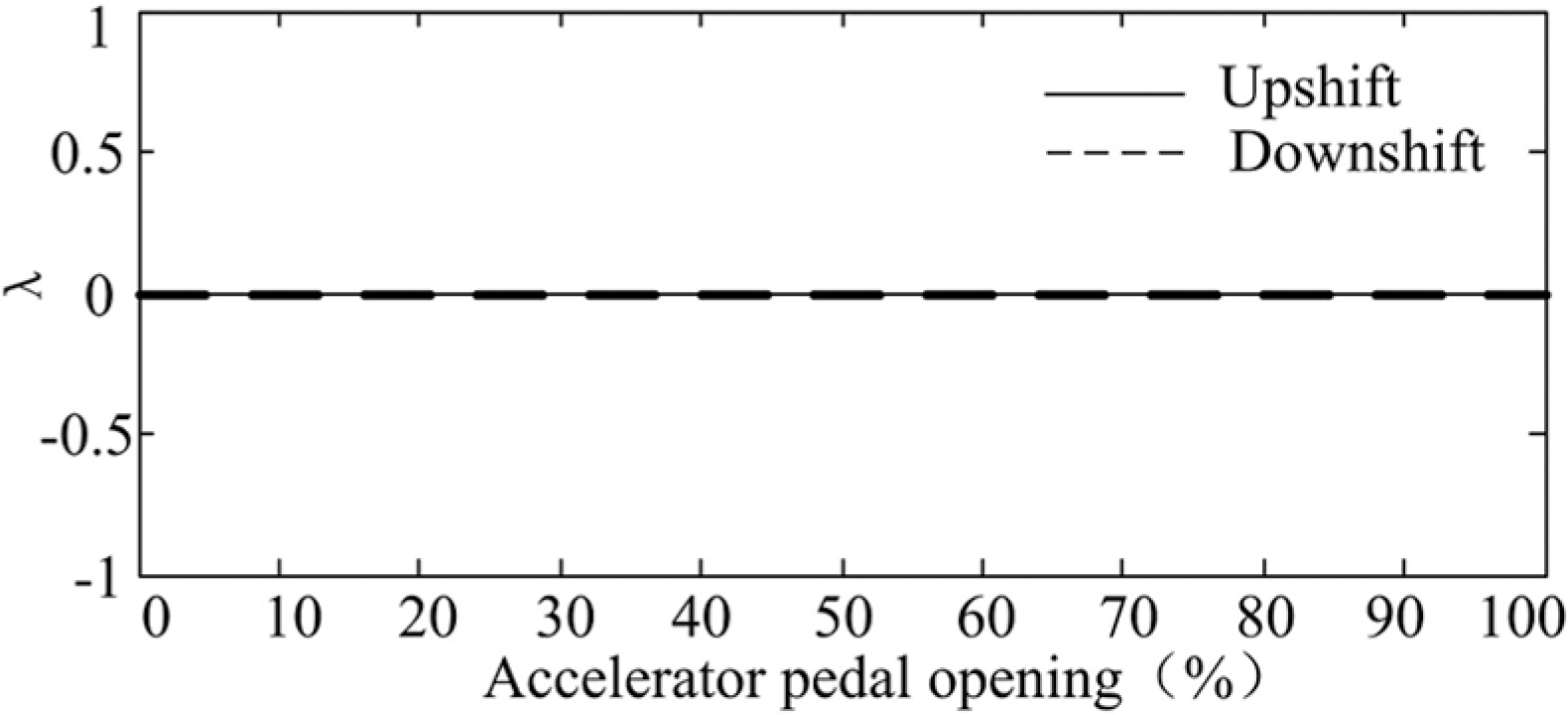
Driving force ripple coefficient for dynamic performance shift schedule.
As shown in Figure 7, since the shift speed exceeds ue2 at all cases, the driving force ripple coefficient curves for the upshift and downshift processes coincide at all accelerator pedal openings, and λ remains zero. Obviously, there is no driving force ripple when applying the dynamic performance shift schedule.
Effect of the economic performance shift schedule on the driving force ripple before and after shift
The economic performance shift schedule is aimed at taking full advantage of the high efficient area of the motor. Therefore, the economic performance shift schedule can be acquired using the efficiency curves in the two gears.13,14 The obtained schedule is shown in Figure 8. Using this schedule, the relationship between the driving force ripple coefficient λ and accelerator pedal opening is plotted in Figure 9.

Economic performance shift schedule.

Driving force ripple coefficient for economic performance shift schedule.
In the results shown in Figure 9, all absolute values of λ are greater than zero, because the shift speed is less than the vehicle speed ue2 at all times. Apparently, there exist driving force ripples when the economic performance shift schedule is applied. Thus, in order to suppress the ripple phenomenon, this article proposes a torque compensation strategy for the economic performance shift schedule.
Torque compensation strategy
According to the preceding analyses, it is not necessary to compensate torque when applying the dynamic performance shift schedule. However, when adopting the economic performance shift schedule, torque compensation is necessary. Hence, in this section, a torque compensation strategy for a two-speed AMT is presented in detail.
Torque compensation strategy
The driving force under a certain accelerator pedal opening is shown in Figure 10, where

Driving force under a certain accelerator pedal opening.
Torque compensation strategy in the upshift process
As seen in Figure 10, when the vehicle speed increases to
According to Figure 10, when the vehicle speed is greater than

where
The motor speed

where i2 is the gear ratio of the second gear, and r is the tire radius. The compensation torque

Torque compensation strategy in the downshift process
As shown in Figure 10, when the vehicle speed reduces to

where
The motor speed

The compensation torque

It is seen from the preceding discussions that the proposed torque compensation strategy is aimed at compensating the motor output torque when the two-speed AMT is at the second gear and vehicle speed is between

where
In case of a large accelerator pedal opening, the total motor output torque calculated by equation (8) could become greater than the maximum motor output torque. In this case,

where
Based on the above analyses, when the accelerator pedal opening is
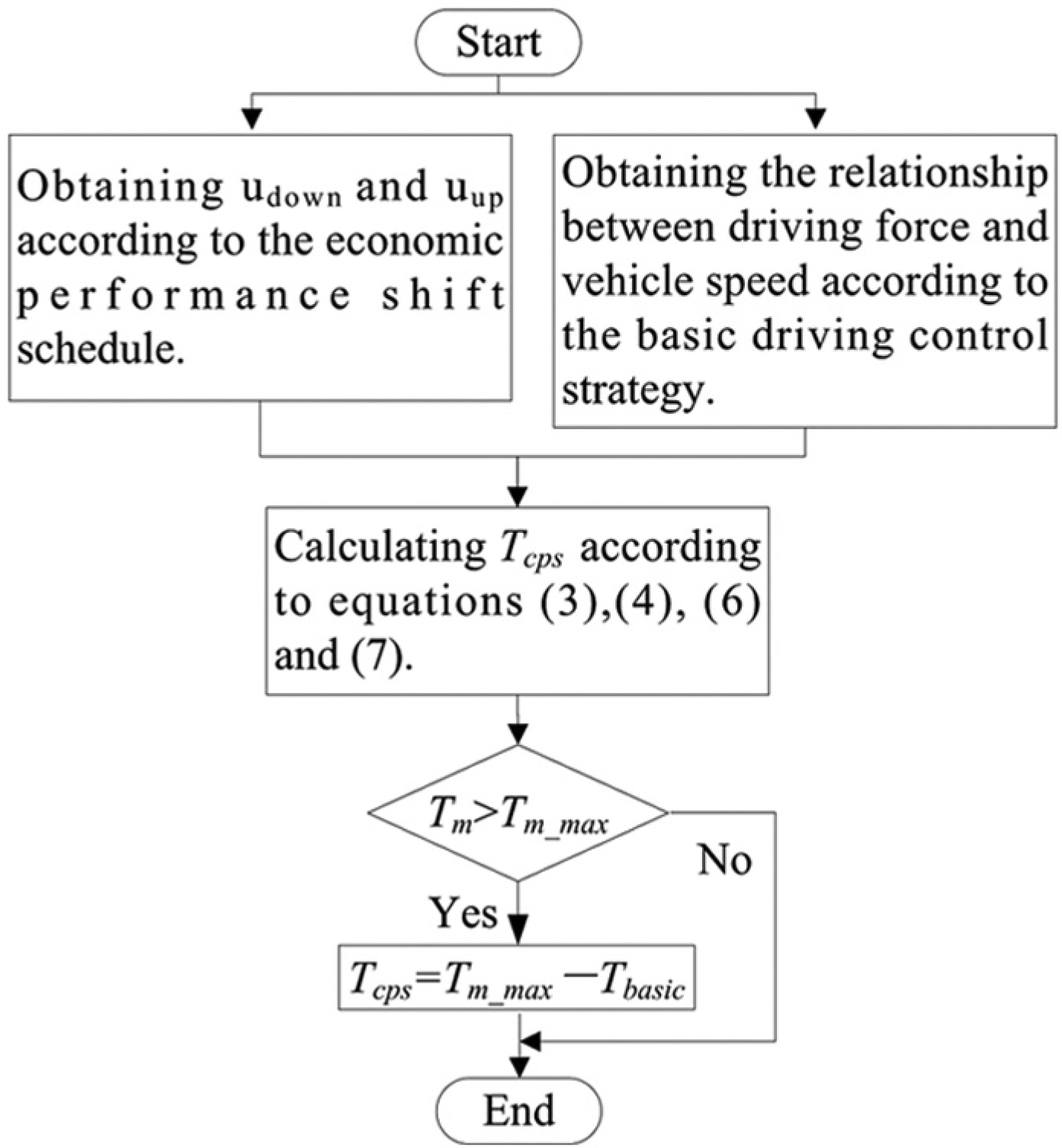
Compensation torque calculation process with a certain accelerator pedal opening.
Following Figure 11, the value of the compensation torque under different accelerator pedal openings is calculated, as shown in Figure 12. Besides, the driving control strategy after torque compensation is also obtained using Figures 5 and 11, and it is plotted in Figure 13. As shown in Figures 12 and 13, when the accelerator pedal has a small- or medium-sized opening, the compensation torque increases with the accelerator pedal opening. However, if the accelerator pedal opening is large, the compensation torque decreases as the accelerator pedal opening increases, because the motor reserve-power decreases continuously with the increase in the accelerator pedal opening.

Relationship between compensation torque and motor speed at different accelerator pedal openings.

Relationship between motor torque and motor speed at different accelerator pedal openings after torque compensation.
Validation and analysis of the torque compensation strategy
Considering Figure 13 and the economic performance shift schedule, the driving force during the shift process before and after torque compensation is plotted in Figure 14. The results in Figure 14 indicate that when the accelerator pedal opening is less than 50%, the driving force ripple before and after shift can be completely eliminated by means of torque compensation. If the accelerator pedal opening is more than 50%, the torque compensation can attenuate the driving force ripple before and after shift.

Driving force before and after torque compensation: (a) driving torque chart before torque compensation in the upshift process, (b) driving torque chart after torque compensation in the upshift process, (c) driving torque chart before torque compensation in the downshift process, and (d) driving torque chart after torque compensation in the downshift process.
The driving force ripple coefficient during the shift process can be calculated under different accelerator pedal openings, using Figure 13 and equation (1). Therefore, the relationship between the driving force ripple coefficient λ and the accelerator pedal opening is plotted in Figure 15 with the economic performance shift schedule.

Relationship between driving force ripple coefficient λ and accelerator pedal opening.
The results in Figure 15 demonstrate that when the accelerator pedal opening is less than 50%, the absolute value of λ is zero and the driving forces before and after shift are equal. When the accelerator pedal opening is more than 50%, the torque compensation strategy can only reduce the absolute value of λ, thus weakening the driving force ripple. In summary, the proposed torque compensation strategy can effectively suppress the driving force ripple before and after shift.
Simulation studies
A simulation model for a pure electric vehicle is established in the MATLAB/Simulink environment, and then the proposed torque compensation control strategy is verified through computer simulation. Since the torque compensation control strategy aims to determine the target value of the motor torque in the shift process, no sub-models simulating the shift process are employed, and it is assumed that the two-speed AMT immediately shifts to the target gear after receiving the shift order. The four driving modes shown in Table 2 are adopted in the simulation. According to section “Validation and analysis of the torque compensation strategy”, in the simulation studies, we focus more on the situations with accelerator pedal openings less than 50%.
Driving modes for simulation.

Simulation studies on upshift and downshift
The simulation results for upshift are shown in Figure 16, with an accelerator pedal opening of 30% and zero gradient. As seen from Figure 16(a) and (b), the torque compensation strategy improves the vehicle dynamic performance after upshift, namely, the vehicle speed increases faster. Because the vehicle acceleration is proportional to the driving force, the variation in vehicle acceleration is used to reflect the vehicle driving force change in this article, as shown in Figure 16(c). It is also evident in Figure 16(c) that the acceleration ripple can be eliminated before and after upshift by means of the proposed torque compensation strategy.

Simulation results for upshift with an accelerator pedal opening of 30% and zero road gradient: (a) vehicle speed chart before and after torque compensation in the upshift process with an accelerator pedal opening of 30% and zero road gradient, (b) motor torque chart before and after torque compensation in the upshift process with an accelerator pedal opening of 30% and zero road gradient, (c) Acceleration chart before and after torque compensation in the upshift process with an accelerator pedal opening of 30% and zero road gradient, and (d) gear state chart before and after torque compensation in the upshift with an accelerator pedal opening of 30% and zero road gradient.
The simulation results for downshift are shown in Figure 17, with an accelerator pedal opening of 30% and a gradient of 10%. The results in Figure 17 demonstrate that the acceleration ripple can be eliminated before and after downshift by means of the proposed torque compensation strategy, and the vehicle acceleration changes continuously in the downshift process.

Simulation results for downshift with an accelerator pedal opening of 30% and a road gradient of 10%: (a) vehicle speed chart before and after torque compensation in the downshift process with an accelerator pedal opening of 30% and 10% road gradient, (b) motor torque chart before and after torque compensation in the downshift process with an accelerator pedal opening of 30% and 10% road gradient, (c) Acceleration chart before and after torque compensation in the downshift process with an accelerator pedal opening of 30% and 10% road gradient, and (d) gear state chart before and after torque compensation in the downshift process with an accelerator pedal opening of 30% and 10% road gradient.
To sum up the above simulation results, with a small or medium acceleration pedal opening, the driving force ripple can be completely eliminated before and after shift by adopting the proposed torque compensation strategy, and the vehicle driving comfort is improved.
The simulation results for upshift with an accelerator pedal opening of 70% and zero road gradient are shown in Figure 18. We see from Figure 18(a) and (b) that when the torque compensation strategy is employed, the vehicle dynamic performance is improved, namely, the vehicle speed increases faster after upshift. The results in Figure 18(c) indicate that the vehicle acceleration experiences a sudden drop after the upshift, no matter the basic driving control strategy or torque compensation strategy is adopted. However, the vehicle acceleration drops less with the driving torque compensation strategy on-board. In other words, the driving torque compensation strategy can attenuate the driving force ripple before and after upshift.

Simulation results for upshift with an accelerator pedal opening of 70% and zero road gradient: (a) vehicle speed chart before and after torque compensation in the upshift process with an accelerator pedal opening of 70% and zero road gradient, (b) motor torque chart before and after torque compensation in the upshift process with an accelerator pedal opening of 70% and zero road gradient, (c) Acceleration chart before and after torque compensation in the upshift process with an accelerator pedal opening of 70% and zero road gradient, and (d) gear state chart before and after torque compensation in the upshift process with an accelerator pedal opening of 70% and zero road gradient.
Thus, by means of the proposed torque compensation strategy, the driving force ripple can be effectively weakened before and after shift, and the vehicle dynamic performance and driving comfort can be improved.
Simulation studies on shift cycle
The simulation results for shift cycle are shown in Figure 19, with an accelerator pedal opening of 50% and a road gradient of 12%. The results in Figure 19 show that when only the basic driving control strategy is used, shift cycle happens which severely degrades driving comfort. While the driving torque compensation strategy is employed, there is no driving force ripple before and after shift, and the phenomenon of shift cycle is also avoided.
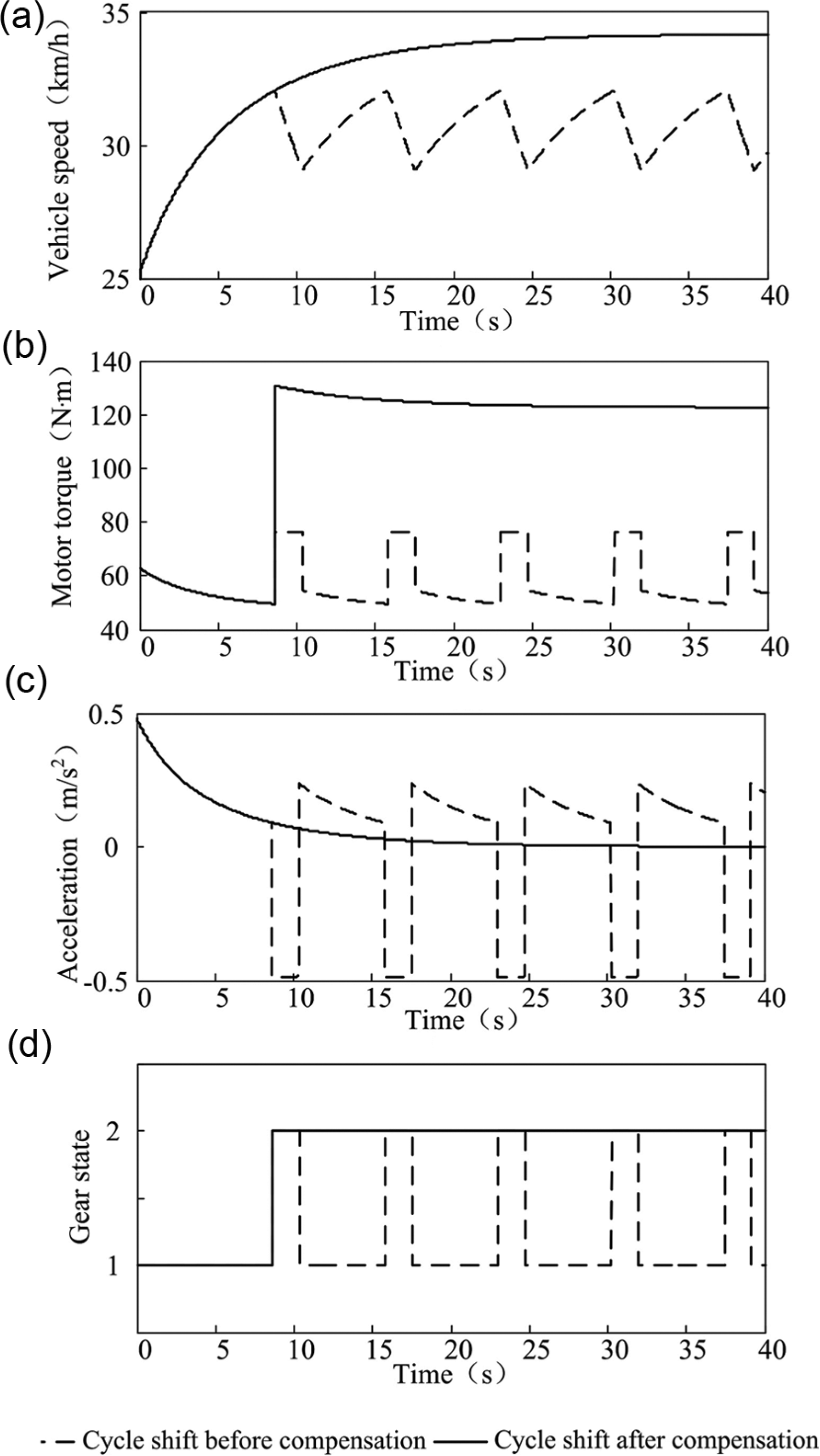
Simulation results for cyclic shift with an accelerator pedal opening of 50% and a road gradient of 12%: (a) vehicle speed chart before and after torque compensation in the cyclic shift simulation with an accelerator pedal opening of 50% and 12% road gradient, (b) motor torque chart before and after torque compensation in the cyclic shift simulation with an accelerator pedal opening of 50% and 12% road gradient, (c) Acceleration chart before and after torque compensation in the cyclic shift simulation with an accelerator pedal opening of 50% and 12% road gradient, and (d) gear state chart before and after torque compensation in the cyclic shift simulation with an accelerator pedal opening of 50% and 12% road gradient.
In short, with a small or medium accelerator pedal opening, shift cycle can be completely avoided and the vehicle driving comfort can be enhanced by means of the proposed torque compensation strategy.
Conclusion
In this article, the phenomenon of driving force ripple before and after shift for pure electric vehicles equipped with two-speed AMT was studied. The following points can be concluded based on the analyses in this work:
Based on the basic driving control strategy for pure electric vehicles, the torque compensation strategy for the two-speed AMT was proposed.
Considering the driving characteristics of the motor, the torque compensation strategy proposed in this article was analyzed theoretically and by simulation.
The results of theoretical analysis and simulation studies indicate that with the economic performance shift schedule, the driving force ripple can be eliminated using the proposed strategy, with an accelerator pedal opening less than 50%. Also, the ripple can be attenuated when the accelerator pedal opening exceeds 50% with the same shift schedule. Moreover, shift cycle caused by the driving force ripple before and after shift can also be avoided.
Footnotes
Academic Editor: Crinela Pislaru
Declaration of conflicting interests
The author(s) declared no potential conflicts of interest with respect to the research, authorship, and/or publication of this article.
Funding
The author(s) disclosed receipt of the following financial support for the research, authorship, and/or publication of this article: This research was supported by the Chongqing Natural Science Foundation (Project No. CSTC2011BA3019). This project offered all the cost of this series researches. The authors appreciated for its support on these researches.