
Abstract
The ball screws are the machine component most frequently used for transforming rotational into linear motion of a feed drive, to position the machine tool components carrying the cutting tool to the desired location. A failure of the ball screw usually leads to a total breakdown of the axis; therefore, the attainable life of this component is an important issue concerning the availability and productivity of modern machine tools. This article presents an approach to evaluate the influence of control parameters on the fatigue life of ball screws based on simulation, by means of a numerical model of a machine tool servo-axis. Ball screw life was evaluated with different conditions, varying the position loop main proportional gain and the kinematic limit conditions for trajectory generation. Furthermore, the mathematical model was used to evaluate optimal control gain and trajectory conditions for a machine tool based on the achievable life span of the ball screw feed drive system, with regard to the desirable performances, such as position accuracy, promptness, and cutoff frequency.
Introduction
The industry demand for increasing productivity has always been crucial for the evolution of computer numerical control (CNC) machines, which are required with high precision and short production times. Ball screw feed drives are the most commonly used mechanisms to provide linear motion in high-speed machine tools to position the cutting tool; hence, their positioning accuracy and speed determine the quality and productivity of machine tools. For a given servo-axis, these features are affected by the criteria used for trajectory generation and by control algorithms. 1 Therefore, a variation in machine performances is made possible by having a tool path generation with higher limited kinematic parameters and by setting the axis position control loop with a higher proportional gain. Of course these parameters must be set within the electromechanical limitations of the actuator and so as to ensure the stability of the machine.
If higher performances are required, it is important to evaluate the operational life reduction of the ball screws for the machine tool, since a failure of the ball screw usually leads to a total breakdown of the axis, causing downtimes for production. 2
The preloading is an important issue concerning the performance of a feed drive, since it has an influence on the rigidity and the dynamical performance of a ball screw; however, increasing the preloading also leads to higher friction which has a negative effect on the thermal behavior, thus on the efficiency and the durability of ball screws. The preloading method and the preload force value strongly affect the actual stress acting on ball screws and fatigue life calculation. The static preload value may vary during ball screw service due to operational conditions. Other works studied the variation in preload during ball screws’ operating life. In Verl and Frey, 3 the correlation between feed velocity and preloading was analyzed, while in Wei et al. 4 a model that predicts the decrease in the preload based on the axial wear depth of the contact areas was developed. New designs for the ball screws were proposed in Verl et al. 5 allowing for a considerable reduction in the preloading with improved overall operational characteristics of ball screws.
In this work, fatigue life was calculated according to ISO 3408-5:2006, 6 considering 60% of the initial preload as a mean value during operational life, analyzing the case of a preloaded ball screw with two points of contact between each ball and the tracks on the shaft and the nut.
The calculation of the nominal life expectancy is based on wear due to material fatigue, and therefore predominantly considers the effective load on the ball screw and its rotational speed. Operating conditions such as shock loads, lubrication, vibrations, temperature, and misalignment also have an influence on the durability of a ball screw and may cause spontaneous breakdowns such as failure, breakage, or contamination; however, they are usually not taken into account when calculating the nominal life.
Other authors studied some of these effects not considered in ISO that affect operating behavior of a ball screw, such as variable loads caused by misalignments due to manufacturing tolerances, 7 failure caused by impacts between the steel balls and the returning tube, 8 and optimal lubrication. 9
This work presents a theoretical analysis of the influence of the control parameters on the machine tool that affect the dynamics of the axis and the life of the ball screw as well, through a simulation approach with nominal fatigue life calculation. The analysis in this article is based on the axis numerical model developed by Mauro et al. 10 and it expands the previous studies.
The forces on the ball screw actually originating from motion or machining processes depend on the response of the machine to an input command. They can be identified by means of simulation methods, as well as the rotational speed of the screw. The identification of load acting on the ball screw and its speed does not only require a model of the axis but also a reference motion profile matching the desired movement of the machine while positioning or machining. Several reference trajectories for the axis were generated with a time-optimal algorithm upon combining different limit conditions on maximum jerk, acceleration, velocity, and stroke.11,12 By combining reference motion profiles with a virtual NC, the motions carried out while running an NC program can be simulated, and the corresponding forces acting on the ball screw can be computed. This information allows for an analysis of the expected service life for different values of the main proportional gain of the position loop Kv and the kinematic limit conditions on trajectory generation. Furthermore, a methodological criterion to optimize the main proportional gain of the position loop and trajectory conditions considering precision, promptness, cutoff frequency, and ball screw fatigue life is presented for the axis.
Description of the machine
The axis studied is part of a commercial horizontal machining center with a Cartesian structure. The main objective of the axis is to position the cutting tool used to contour the raw material of the workpiece, by means of a feed drive.
A general architecture of a ball screw feed drive system is shown in Figure 1. The feed drive is powered by a brushless motor (1) coupled with a screw shaft (2) through an elastic joint (3) to avoid issues of misalignments. The screw shaft is mounted on a roller pack (4) fixed to a metal support (5). The ball screw assembly, composed of a screw (6) and a nut (7), transforms rotational into linear motion. The nut is fixed to the slide (8), so that the turning of the screw generates a linear movement of the slide, which is mounted on recirculating rolling guides (9) to constrain all degrees of freedom but the desired travel direction. The slide is equipped with the cutting tool for machining operations and it is positioned by the feed drive, following a reference trajectory by means of a control system.

Schematic configuration of a ball screw feed drive.
The axis considered in the following analyses has a maximum stroke equal to 500 mm, a translating mass estimated approximately equal to 675 kg, whereas the ball screw has a nominal diameter of 50 mm and a lead of 30 mm.
Mathematical modeling
The mathematical model of the machine tool longitudinal axis is similar to the one developed by Mauro et al., which is here summarized. For a detailed description of the axis model, refer to Mauro et al. 10 A lumped parameter model was assembled starting from a representation of the axis, identifying all the rigid bodies with inertia and connecting them by means of elastic and damping elements, which represent the stiffness and damping coefficient of the bodies mechanically connected in series.
Two subsystems are identified, as shown in Figure 2, connected together by the ball screw coupling. The rotary subsystem (A) comprises the motor shaft (1), the ball screw end (2), and the screw rotational inertia (3), which are connected by the torsion spring and damper k 12, comprising the stiffness and damping of the motor shaft and the elastic joint, and k 23, comprising the ball screw end and the screw. The axial subsystem (B) is composed of the screw axial inertia (4), the ball screw coupling (5), the ball nut (6), and the slide (7). Linear springs and dampers axially connect these elements in series: k 04 comprises the axial support, the bearing pack, and the screw; k 56 represents the system formed by the ball tracks on the screw and nut and the balls, whereas k 67 represents the flange that connects the ball nut to the slide.

Schematic view of the axis for mathematical modeling. (A) Rotary subsystem. (B) Axial subsystem.
The ball screw coupling converts the rotation motion of the screw into the ideal translation motion of the nut. The actual motion of the ball nut is also determined by the stiffness and damping k 56 of the coupling.
Once the scheme of the model was created, two sets of differential equations, the axial and rotational equilibrium equations of each rigid body with inertia, were formulated to describe the dynamics of the axis. In order to reduce the complexity of the model, all friction effects were assumed to be concentrated on the ball screw–nut coupling because of the preload of the ball nut.
Moreover, the actuator of the system was modeled as a direct current (DC) motor driven by a position, velocity, and current control loop hardware. As shown in Figure 3, the deviation between position command and feedback is amplified by means of the proportional gain of the position loop, named Kv , to produce the reference signal for the speed control loop. The velocity loop has a proportional–integrative–derivative (PID) controller. The error between the velocity reference and its actual value is divided into three branches: one of them is multiplied by the gain kp , the other multiplied by ki and then integrated, while the other one is multiplied by the gain kd and then derived. The branches are added producing the current reference signal, which has to be limited to the maximum current of the electric motor. Finally, the current control closed loop produces the armature voltage reference for the motor. The PID parameters of inner loops are fixed, as it usually happens in industrial feed drives.

Axis control loop scheme.
Other control techniques for ball screw drives
Though PID controllers are the industry standard for ball screw feed drives, other control techniques can be implemented. PID controllers are found to be most widely used for ball screw feed drives because of their high adaptability, simplicity, and ease of understanding, designing, and tuning. Despite the popularity of these classical controllers, their performance is limited due to the uncertainties and nonlinearities in systems.
In order to minimize the tracking errors at all times during machining processes, feedback servo controllers must be designed carefully for any conceivable condition. To achieve small tracking errors in various conditions, the servo controllers should compensate for the dynamic variations in the systems. Such variations occur because of nonlinearities and uncertainties inherent to real plants. 13
The most common sources of nonlinearities in ball screw drive systems are friction, structural flexibility, and runout of the ball screw shaft. Furthermore, the high accelerations occurring in the high-speed ball screws are likely to excite the axial–torsional vibration modes of the machine structure. These resonance frequencies of the structure are not constant but depend on the position of the tool in its workspace. The axial–torsional modes limit the bandwidth of the drives; thus, they adversely affect the positioning and tracking accuracy. High-performance motion controllers should take into account these varying resonances. 14 To effectively address these issues in the controller design, various approaches have been proposed.
In Sepasi et al., 13 H∞ controllers for a ball screw drive system are designed such that their parameters are adjusted in real time by the measurable workpiece position to improve the tracking performance and so that their performance is maintained robustly over uncertain mass variation. The improved performance for this control design with respect to classic PID controllers is demonstrated through a ball screw drive experimental setup.
Symens et al. 14 discuss the gain-scheduling control approach for an experimental setup containing a flexible beam of which the stiffness depends on its length. H∞ controllers are designed for several constant beam lengths and are linearly scheduled. Next to this ad hoc linear scheduling, analytically scheduled controllers are synthesized. It is shown that the latter solution allows for improved performance in terms of accuracy and vibration reduction.
In Mohammad et al., 15 a sliding-mode controller with nonlinear sliding surface (NLSS) is proposed to improve the machining accuracy and to reduce energy consumption for ball screw drive systems. Unlike the conventional sliding-mode control design, the proposed NLSS varies according to the output (controlled variable) so that the damping ratio of the system changes from its initial low value to its final high value as the output changes from its initial value to the reference point. The effectiveness of the proposed NLSS, with respect to conventional sliding-mode controllers, is verified experimentally.
In Dong and Tang, 16 the problem of modeling and tracking control for a high-speed ball screw drive is proposed. An adaptive backstepping sliding-mode controller with minimum tracking error prefilter is proposed to actively suppress for the vibrations and achieve high positioning performance. Compared with P/PI controller with the velocity and acceleration feed-forward, the proposed controller has been validated to achieve higher tracking accuracy, bandwidth, and stability.
In Yan et al., 17 a fuzzy logic controller combined with neural network-based feed-forward control is proposed to improve the contouring accuracy of this milling machine through friction compensation. The experimental results show that this control scheme improved not only the contouring accuracy significantly but also the disturbance rejection and robustness, comparing to the conventional control scheme.
However, despite all the advantages shown by advanced control techniques, they do not find, generally, a wide use in industrial applications. This is due to their higher complexity with reference to PID controllers, which involves a larger need of competence for the final user to be efficiently tuned. All the analyses carried out in the following consider servo-axis with PID controllers.
Ball screw life calculation method
Fatigue life calculation according to ISO 3408
According to ISO 3408-5:2006,
6
the nominal life expectancy of a preloaded ball screw based on material fatigue can be estimated through the basic dynamic load rating of the component
The preloading method influences the calculation of the actual axial load exchanged between the screw balls and ball tracks. In this analysis, a commercial double-start ball screw with single preloaded nut with shifted pitch was considered, which achieves two-point contact between the balls and the ball tracks on shaft and nut.
Due to the application of an external axial load, one start of the screw will be additionally loaded and the other one relieved. If the external axial load is higher than the limit force

The external axial force acting on the ball screw during the jth time interval is indicated as


Due to the fact that the preload decreases over the operational life of ball screws, the average operational preload is set to 60% of the original preload, so a value of the operational preload factor
In case of two-point ball contact, the external axial load on the ball screw produces two load spectra for the starts of the screw, so a value of equivalent actual axial load for each one has to be computed,

With the equivalent rotational speed
Therefore, for a two-point-ball-contact preloaded ball screw, two values of fatigue life are obtained,
The resulting life

Ball screw service life may also be expressed in hours or in cycles performed, respectively


Formulations (8) and (9) are valid if
Computation process of fatigue life
The computation process for ball screw life is shown in Figure 4. To evaluate the fatigue life of a ball screw, it is necessary to know its external axial load and rotational speed spectra. The force and the rotational speed actually originating depend on the response of the machine tool axis and can be identified by means of simulation with the servo-axis numerical model described in section “Mathematical modeling.” To compute the system response, it is necessary to define an input command for the mathematical model. The trajectory generated with the desired kinematic limit conditions is used as reference for the virtual NC of the model. It computes the simulated response of the system and in particular the axial external force acting on the ball screw Fbs
and the screw rotational speed n during cycle time. From the spectra of these two quantities, it is possible to calculate nominal fatigue life as shown in section “Fatigue life calculation according to ISO 3408.” With the convention assumed, if Fbs
is positive in the jth time interval, then it coincides with

Computation process.
Machining reference cycles
Ball screw life is strongly dependent on its operating cycle. In order to analyze a relevant number of cases, several typical cycles were generated taking into account only the positioning of the cutting tool, without machining. This assumption was made considering that during machining, the tool moves slowly against the workpiece, so the rotational speed of the screw shaft is very low; hence, even if the force exchanged has a high value, the fatigue stresses that cause life reduction on the ball screw life are negligible according to ISO. Therefore, forces are not exchanged between the tool and the workpiece during the simulated process.
Instead, during the rapid displacement of the slide, which carries the cutting tool for positioning or tool change, the ball screw is subject to fatigue stresses caused by variable external axial loads, mainly due to the inertial force of the slide when it is accelerated or decelerated, and by the preload force. Also, elastic and damping forces were considered in the model, although they play a small role in the overall stress on the ball screw.
Machining typical reference cycle
Controllers for machining tools are commonly driven by means of trajectory generators whose output signals must typically satisfy several requirements. The motion profiles of the axis slide depend on the processes the machine tool must perform, although typical reference cycles may be considered as displacements of the slide along the axis stroke with different amplitudes.
To get continuous acceleration profiles, trajectories are generated from a rectangular-shaped jerk profile, so that the acceleration profile is continuous and the vibrations are reduced. The motion evolves at limit conditions, so maximum jerk jmax , acceleration amax , and velocity vmax are reached, and the time evolution of position is described by a third-order polynomial. Under extreme conditions, that is, tiny displacements, the third-order planner might fail due to numerical problems, 11 consisting in the fact that there is not enough time to reach the maximum value of the velocity imposed. In this case, in order to overcome numerical problems for minimum time trajectory generation, the cruising speed phase has to be omitted and the value of maximum velocity may be lower than the limit imposed.
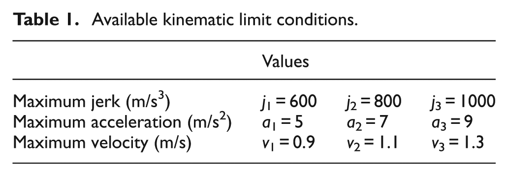
The reference trajectories were generated considering different values for maximum jerk, acceleration, velocity, and axis stroke. Table 1 summarizes the kinematic limit conditions, while strokes were considered varying from 20% to 100% of the maximum axis stroke. Figure 5 shows a set of sample trajectories with different stroke, whereas Figure 6 shows the variation in the reference trajectories due to a change in kinematic limit conditions.
Available kinematic limit conditions.

Standard reference cycles with variable axis stroke (kinematic limits: j 2, a 2, v 2).

Trajectory generation with different kinematic limit conditions (kinematic limit: 100% stroke).
Ball screw life analysis in relation to parameters
To evaluate the effect of the different reference trajectories generated on ball screw life, nominal conditions were considered at first when computing fatigue life of the component. This means that in this case, the position feedback of the system was assumed coincident with the position reference. All friction and damping effects were neglected and the bodies were considered perfectly stiff. Thus, the external load acting on the ball screw in nominal conditions is only due to the inertial properties of the slide and ball nut, while the rotational speed of the screw is proportional to the linear speed of the slide.
Ball screw fatigue life was calculated for different percentages of the maximum axis stroke performed in a displacement cycle. Figure 7 shows the distribution of service life results obtained for each stroke value considered and different combinations of kinematic limits in trajectory generation; the points correspond to one of the 27 combinations of the parameters of Table 1 assumed for maximum jerk, acceleration, and velocity. For greater axis strokes performed, the life of ball screw diminishes, since preload acts on the screw for a greater number of revolutions. At the same time, the distribution of ball screw life values is less spread, which means that kinematic limit conditions have less influence. The figure puts in evidence that the selection of parameters of Table 1 strongly affects the fatigue life of the ball screw; in fact, it can almost double with a correct parameter selection.
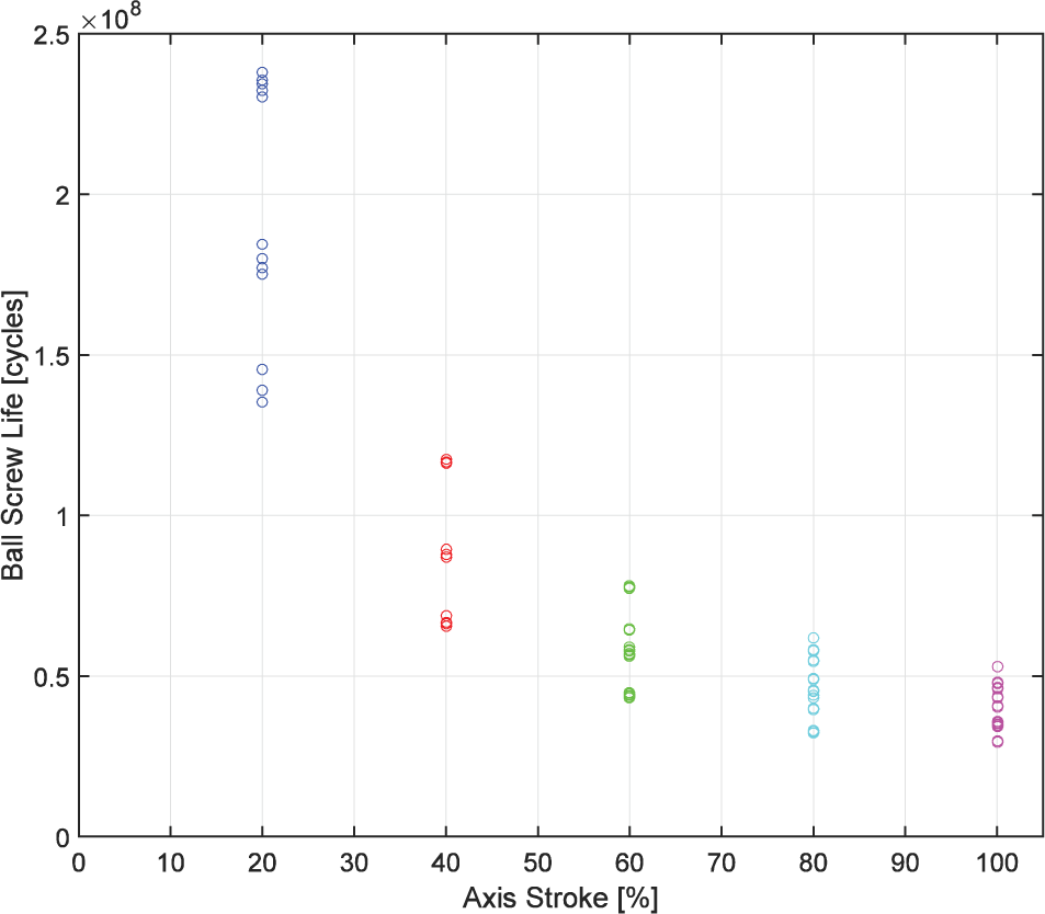
Ball screw life distribution varying kinematic limit conditions for different values of the axis stroke.
However, the kinematic parameters also influence the axis performance and especially the time requested to perform a cycle. In order to consider this aspect, the reference cycles generated with different limit conditions were computed. For each of them, the effect of limited values of maximum jerk, acceleration, and velocity on ball screw life and response time was analyzed. The response time τ was computed as the time the axis needs to travel from the middle stroke to 99% of the maximum stroke commanded, to evaluate the dynamic response of the axis.
Focusing on a certain value of the stroke performed by the slide (100% of full stroke), a ranking of different kinematic limit conditions for trajectory generation was created, which is graphically represented in Figure 8. The first rank in terms of durability is meant for the conditions generating a displacement cycle with great durability of ball screws. In terms of response time, the first rank refers to the cycle that requires the shortest amount of time to perform the displacement. As expected, the ranking shows that by increasing the limit conditions for trajectories, the fatigue life decreases, as well as the response time of the axis.
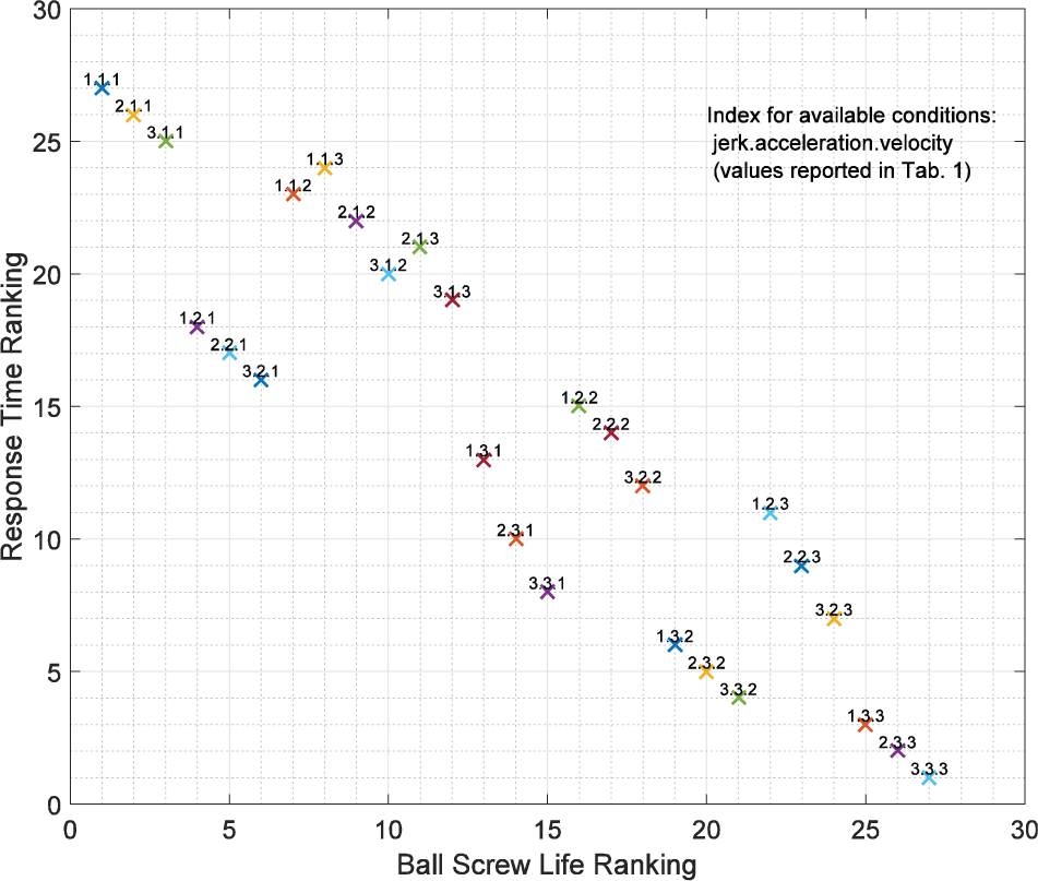
Ranking of available kinematic limit conditions for trajectory generation in nominal case (kinematic limit: 100% stroke).
Subsequently, evaluations were made with the realistic response of the system computed by means of simulation based on the numerical model developed, varying the position loop main proportional gain Kv and considering each preset of trajectory conditions.
Figure 9 shows the trajectories obtained with different values of Kv coefficient, for a given condition of the position reference: j 2, a 2, v 2, and 100% of maximum stroke. Figure 10 shows actual axial force on ball screw and screw rotational speed spectra for different values of Kv , considering the same position reference.

Simulated position feedback with variable Kv (kinematic limits: j 2, a 2, v 2, and 100% stroke).

Actual axial force and rotational speed of ball screw depending on variable Kv (kinematic limits: j 2, a 2, v 2, and 100% stroke).
Table 2 shows the equivalent actual axial load and the expected ball screw life, computed combining the previous data. As said in section “Fatigue life calculation according to ISO 3408,” there are two computed values of the equivalent actual axial load, one for each start of the screw, but only one was reported since the motion profile selected produces the same equivalent forces on both the starts. In Table 2, it can be seen that, because of the effect of the dynamic response of the mechanical system, the computed fatigue life is different from the nominal value and it can be shorter or longer depending on the value of Kv .
Comparison of estimated ball screw life between nominal and realistic case (kinematic limit conditions considered: j 2, a 2, v 2, and 100% stroke).

It is relevant to point out that a variation in Kv can lead to a variation in the expected life within a span of 29% of its nominal value, whereas a variation in the parameters for trajectory generation can cause a variation in the expected life even larger than 100%, as previously highlighted for Figure 7.
Selection of optimal kinematic limit conditions and Kv
Kinematic limit conditions and control gain Kv
strongly influence the performance of the axis, not only in terms of fatigue life but also in terms of position accuracy, frequency response, and promptness. In order to select an optimal set of values, a cost function that considers axis response time
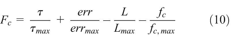
If displacement time and position error are seen as a cost, high service life of ball screw will decrease it, as well as a high value of cutoff frequency of the system. The maximum values of these quantities were evaluated among all the results obtained and they were used to express these quantities in a dimensionless form. The cost function mentioned may be written as follows
with 2 as upper limit and −2 as the lower one. The combination of Kv
, jmax
, amax
, and vmax
that produces the lowest value of
Table 3 shows the values of the terms appearing in the cost function and its value for three different combinations of kinematic limit conditions (1, 2, 3 referring to Table 3) with maximum axis stroke and for different values of Kv . The frequency response was computed considering an amplitude value that does not involve the overcoming of maximum jerk, acceleration, and velocity.
Values for calculation of cost function with variable Kv and kinematic limit conditions.

Kinematic limit conditions considered are as follows: Case 1 (j 1, a 1, v 1), Case 2 (j 2, a 2, v 2), Case 3 (j 3, a 3, v 3), and 100% stroke.
Figure 11 shows a graphical representation of the results in Table 3. For different trajectory generation limit conditions, the cost function diminishes with the increase in Kv . Furthermore, with the same value of proportional gain, the cost function decreases when considering lower limit conditions for trajectory generation. The condition with Kv = 5 × 10³/min−1 and Case 1, shown in Figure 11, is the most effective one.
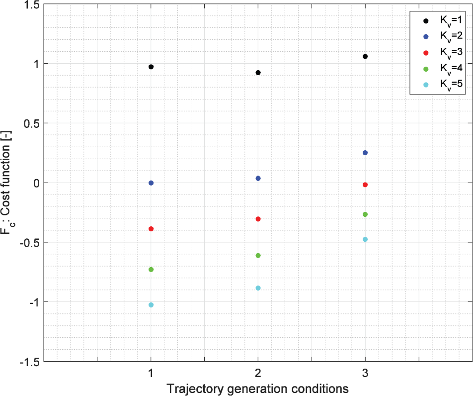
Cost function with variable Kv and kinematic limit conditions.
Conclusion
The results obtained in this work show at first how kinematic parameters used for the generation of the reference trajectories can have a strong influence on the expected life of the ball screw of a feed drive. Furthermore, for a defined criterion to generate trajectories, the proportional gain of the position control of the driver influences the expected life of the ball screw too. However, this last effect is less relevant than that of the trajectory generation parameters, as it was found that the latter can cause a large variation in ball screw life, whereas the controller gain can cause a less effective variation. These results were obtained simulating the machine operation by means of a dynamic model of the servo-axis and processing its output data according to ISO 3408.
All these parameters affect not only ball screw life but also the performance of the servo-axis, particularly in terms of response time, precision, and frequency response. A cost function was created to select the optimal kinematic parameters for trajectory generation as well as the optimal controller gain.
The proposed method was applied to reference trajectories which are not associated with the production of a particular part. In an actual application, the reference cycle should be the cycle performed by the axis during production, so that simulation could compute forces and torques applied during the expected production cycle. In this way, it would be possible to compute the optimal controller set for a particular process. This could provide the user of the machine with a general instrument to set the controller in order to optimize the balance between productivity, which is strictly connected to axis performance, and ball screw life.
Footnotes
Acknowledgements
The authors would like to thank Tharek Mohtar for sharing his previous work and his knowledge on the modeling of machine tool servo-axis.
Academic Editor: Anand Thite
Declaration of conflicting interests
The author(s) declared no potential conflicts of interest with respect to the research, authorship, and/or publication of this article.
Funding
The author(s) received no financial support for the research, authorship, and/or publication of this article.