
Abstract
As for the machine tool with high-speed ball screw feed system, the quite large friction force may change the real contact state of kinematic joints, which would further affect the dynamic characteristics of the whole system. In this article, an equivalent dynamic model of high-speed ball screw feed system was established using hybrid element method. The equivalent axial stiffness of individual kinematic joint and system transmission stiffness were all derived considering the influence of feed rate. The variation in the system natural frequency with feed rates was analyzed using the model proposed and also verified by experiments. The results show that the system natural frequency in motion state is larger than that in static state and behaves differently in different feed rates. The equivalent axial stiffness of the rear-end support bearing unit can reduce to 0 as the feed rate increases, which further leads to a critical value for system natural frequency. In the high-speed motion of the feed system, resonance may occur when the system natural frequency is almost same to the torque ripple harmonic frequency of the servo motor.
Keywords
Introduction
Feed system is one of the most important subsystems of a typical machine tool 1 and its dynamic characteristics play a significant role in control performance,2–4 machining accuracy1,5–7 and the stability of cutting process. 8 Ball screws, popular transmission components, are widely used in feed systems. A volume of research, therefore, has been conducted on dynamic characteristics of the ball screw feed system.
As a result of the flexibility of ball screws, Timoshenko beam was always used because it considers the effects of shear and also of rotational inertia in the beam equation, for example, Pislaru et al., 9 Whalley et al. 10 and Okwudire and Altintas. 11 On the other hand, solid model was also adopted for ball screws and other components in machine tool. Mi et al. 12 established a finite element model of a horizontal machining center including kinematic joints in the feed system and analyzed the influence of preloads on ball screws and linear guides. Their results indicate that the preloads have significant effects on the dynamic stiffness in the transmission direction. In 1999, Tlusty et al. 13 studied the serial and parallel kinematics for machine tools and concluded that the stiffness behaves great difference owing to the position variation in feed systems. In 2001, Van Brussel et al. 14 studied the dynamics of a three-axis machine tool at 27 positions (three positions of each axis) by using finite element method and found that its dynamics are also different. Based on the conclusions by Tlusty et al., Henninger and Eberhard 15 further performed the computation of stability diagrams owing to the position-varying dynamics of the machine tool, which limits the achievable productivity and performance in the whole working range of the machine. Law et al.16,17 modeled the dynamics of a machine tool by synthesizing its substructures’ reduced order finite element models and the results indicate that the machine tool possessed position-dependent dynamics and stability. In 2010, Verl and Frey 18 experimentally found that the preloads of the screw nut joint varied with the system feed rates. All these researches above made great contributions to the understanding of the dynamic characteristics of a ball screw feed system.
Nowadays, machine tools with high feed rate are popularly used and the associated friction force also increases to a considerable value.19–21 The force can change the real contact state of kinematic joints, resulting in the changes in the contact stiffness and the transmission stiffness, which would further affect the system dynamic characteristics. In this article, therefore, an equivalent dynamic model was established using hybrid element method for a high-speed ball screw feed system. A variable-coefficient motion equation was derived considering the influence of the feed rate. The variation in the system natural frequency with feed rates was also discussed.
Dynamic model of a ball screw feed system considering the influence of feed rate
Equivalent dynamic model
A typical ball screw feed system of computer numerical control (CNC) machine tool is mainly composed of worktable, screw shaft, screw nut, bearing units, linear guide and slider, as shown in Figure 1. The worktable in transmission direction is constrained by the screw shaft, screw nut and bearing units. Compared with that in other directions, the stiffness in the transmission direction is smaller because of those kinematic joints and flexible components, and the associated dynamic characteristics of the system in the transmission direction affecting the machining quality will be discussed here.
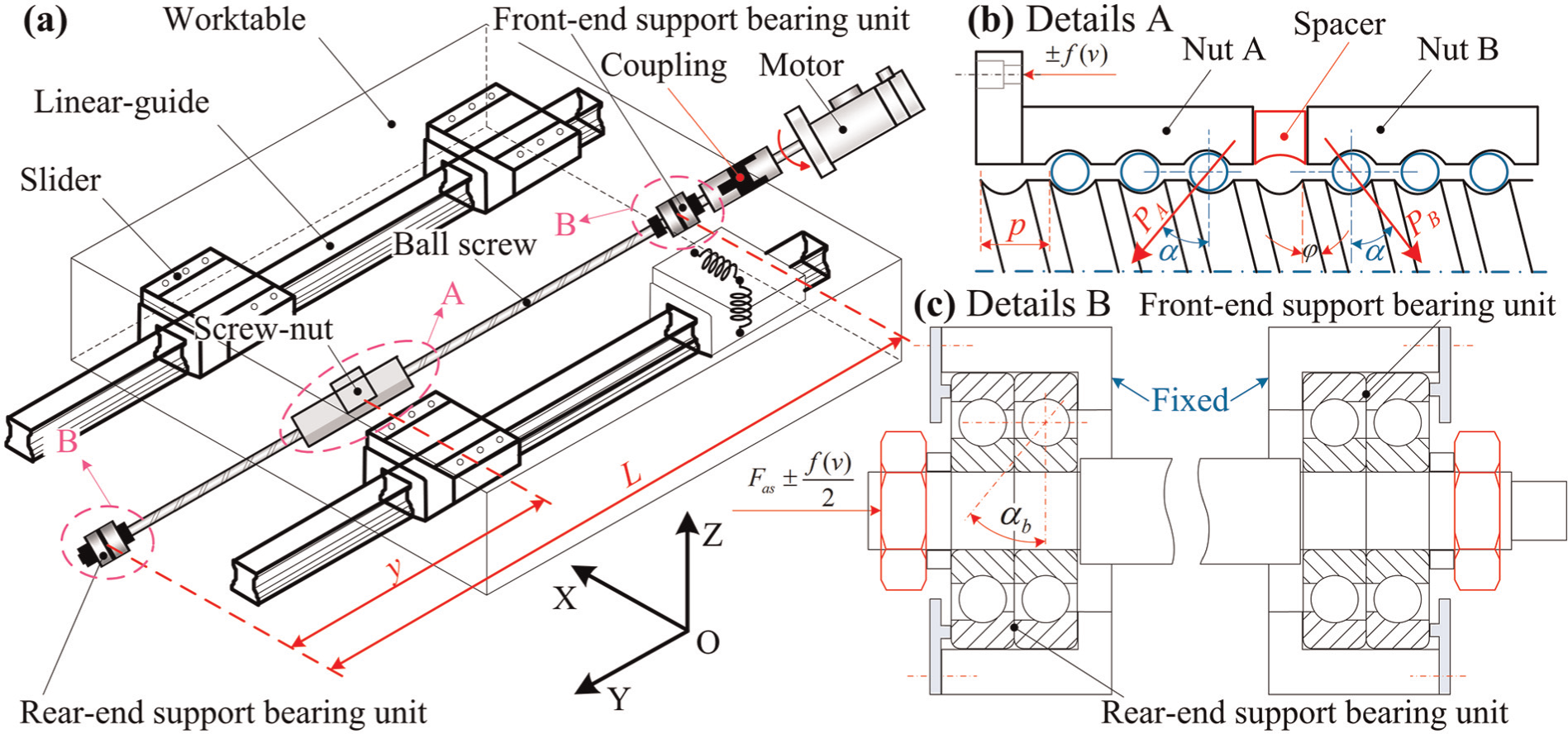
The structure schematic diagram of a ball screw feed system.
In the equivalent model, therefore, the screw shafts on both sides of the nut are equivalent to Timoshenko beam elements with two nodes and 4 degrees of freedom (DOFs) (displacement and rotations at both the ends). The bearing joints and the screw nut joints are both equivalent to lumped spring elements and their stiffness can be determined by multiplying a coefficient of 0.9 considering the flexibility of the bearing housing and nut bracket and the tangential stiffness of the fixed joints. The worktable is treated as a lumped mass element. Neglecting the influence of the servo stiffness, we can establish the equivalent dynamic model in transmission direction considering the influence of the feed rate, as shown in Figure 2.
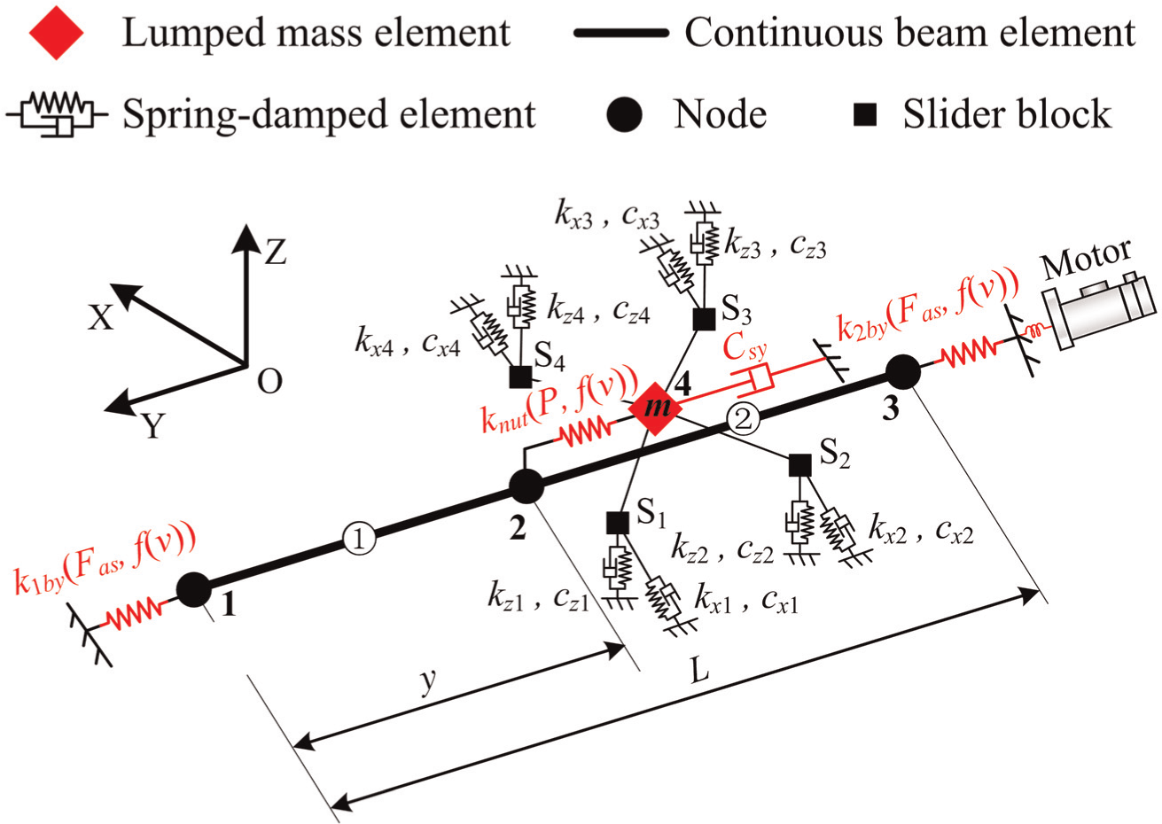
The equivalent dynamic model of the ball screw feed system.
Model’s equation of motion
According to the equivalent dynamic model and D’Alembert principle, a variable-coefficient motion equation of the ball screw feed system can be established as equation (1) considering the influence of feed rate
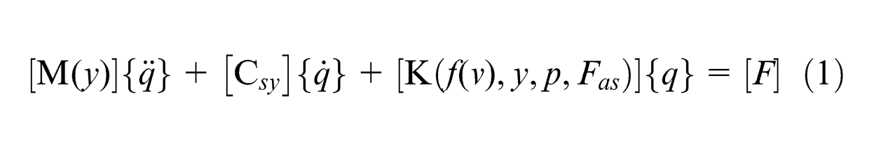
where M(y), C sy and K(f(v), y, p, Fas) are the system mass, damping and stiffness matrix, respectively. The total stiffness is calculated by individual part stiffness including the axial stiffness of the screw nut joints and bearing joints, and the tension/compression and torque stiffness of the screw shaft. It depends on the friction force, worktable position, screw pitch and screw tension force. Friction force f(v) can be determined by the model 19 as follows
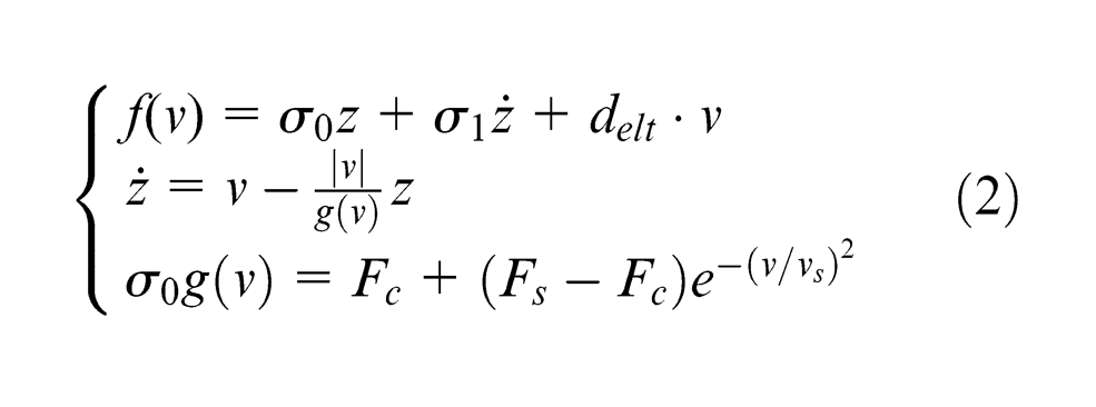
where z is the average deformation of the mane; v and vs are the feed rate and the Stribeck velocity; σ0 and σ1 are the stiffness and the damping coefficient; Fc and Fs are the Coulomb friction and the maximum static friction force and delt is the viscous friction coefficient.
When the feed system moves in a uniform speed, and then
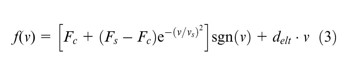
Equation (3) describes the relationship between friction force and feed rate, where the coefficients can be acquired by using the nonlinear identification method.
Calculation of the system stiffness and mass matrix
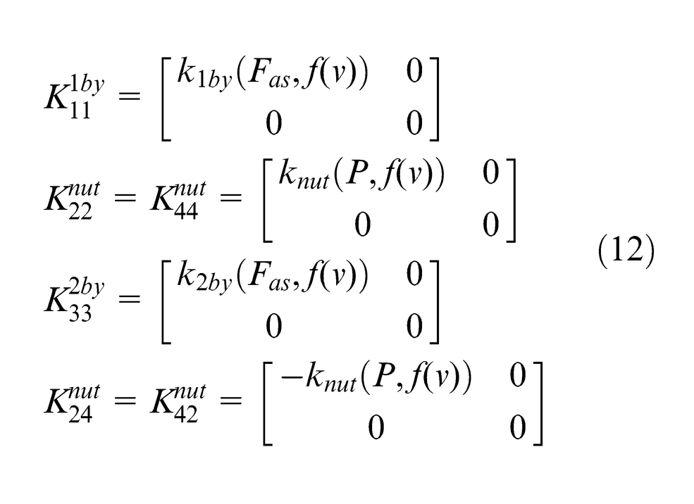
1. Equivalent axial stiffness of the screw nut joints
Figure 1(b) shows the cross section of the screw nut joints for a typical gasket-type double-nut ball screw. Considering the influence of the system feed rate and assuming an elastic deformation only for the balls between screw shaft and nut, we can derive the equivalent axial stiffness of the screw nut joints by equation (4) using the Hertz contact model 22
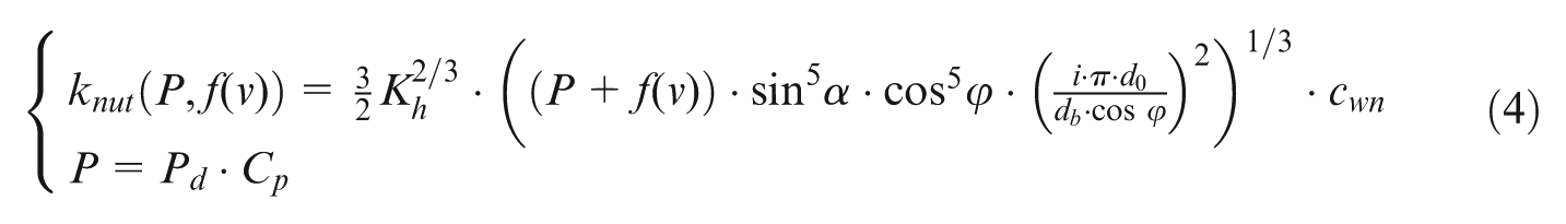
where Pd and Cd are the rated dynamic load of the screw nut joints and the coefficient of the rated dynamic load, respectively; α and ϕ are the contact angle of the screw nut joints and the lead angle of the screw, respectively; i is the total number of load-bearing ring of the single nut; d0 and db are the nominal diameter of the screw and the diameter of the ball in screw nut joints, respectively; cwn is a weight coefficient of equivalent axial stiffness of the screw nut joints, and cwn = 0.9; f(v), friction force, is the function of the feed rate and Kh is the Hertz contact coefficient and is determined by the contact shape of the screw nuts and the material properties.23,24
2. Equivalent axial stiffness of bearing joints
Figure 1(c) depicts the assembly structure of the supporting bearing units in the feed system as well as the applied force in motion state. Supposing the friction force equivalently applied on both bearings with same value but opposite direction, we can obtain the equivalent axial stiffness of the rear-end and front-end support bearing (type: angular contact bearing) by equations (5) and (6)
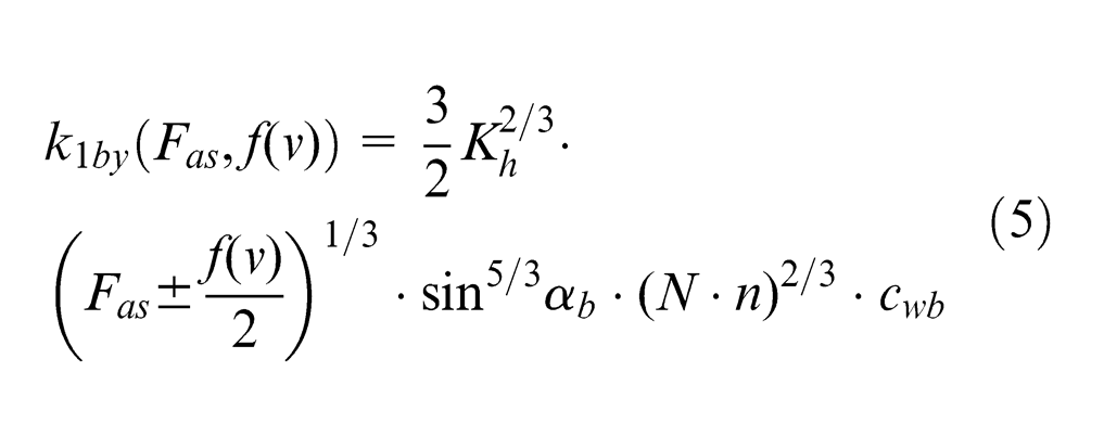
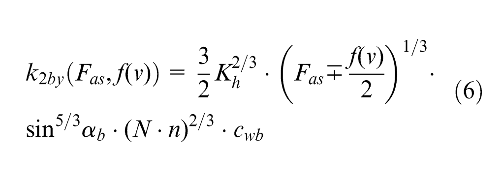
where Fas and αb are the screw tension force and the contact angle of bearing, respectively; N and n are the number of single-ended load-bearing and the ball number of a bearing, respectively, and cwb is the coefficient of equivalent stiffness of bearing joints, and cwb = 0.9.
3. Stiffness and mass matrix of the equivalent Timoshenko beam element
The stiffness matrix of the equivalent Timoshenko beam element ① can be expressed as equation (7) 25
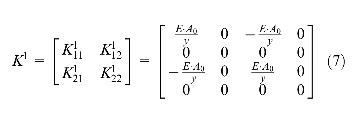
where E is the Young’s elastic modulus and A0 is the cross-sectional area of the bottom diameter of the screw shaft. For element ②, the stiffness matrix can be derived as equation (8) considering the influence of the screw pitch
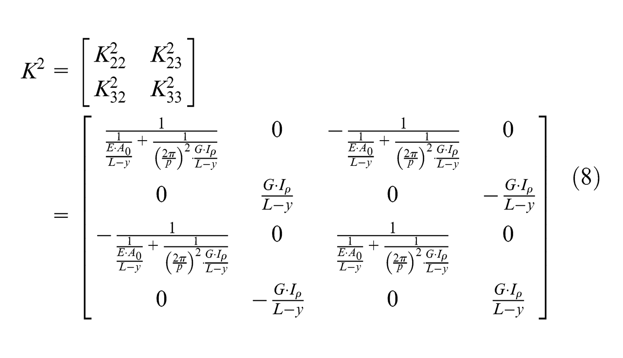
where G is the shear modulus, p is the screw pitch and Iρ is the polar moment of inertia for beam element.
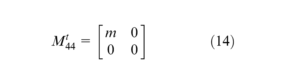
The mass matrices of the equivalent Timoshenko beam element ① and ② vary with the worktable position and are given by equations (9) and (10) 25
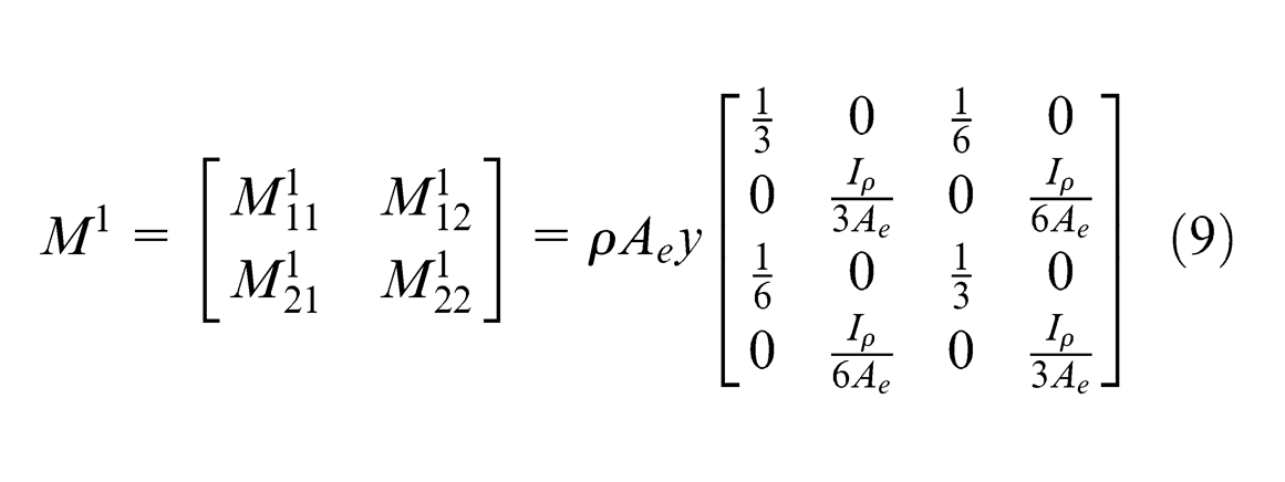
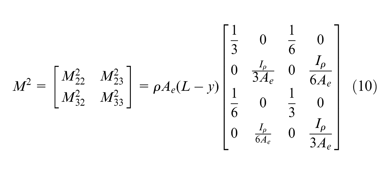
where ρ is the material density and Ae is the cross-sectional area of the equivalent Timoshenko beam element.
4. Total stiffness and mass matrix of the feed system
According to the stiffness matrix of each element, the expression of total stiffness matrix can be derived using the finite element method 25
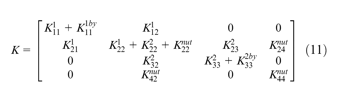
where
In the same way, the total mass matrix of the feed system is
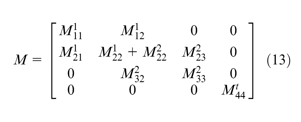
where
Experimental testing of the feed system in static and motion state
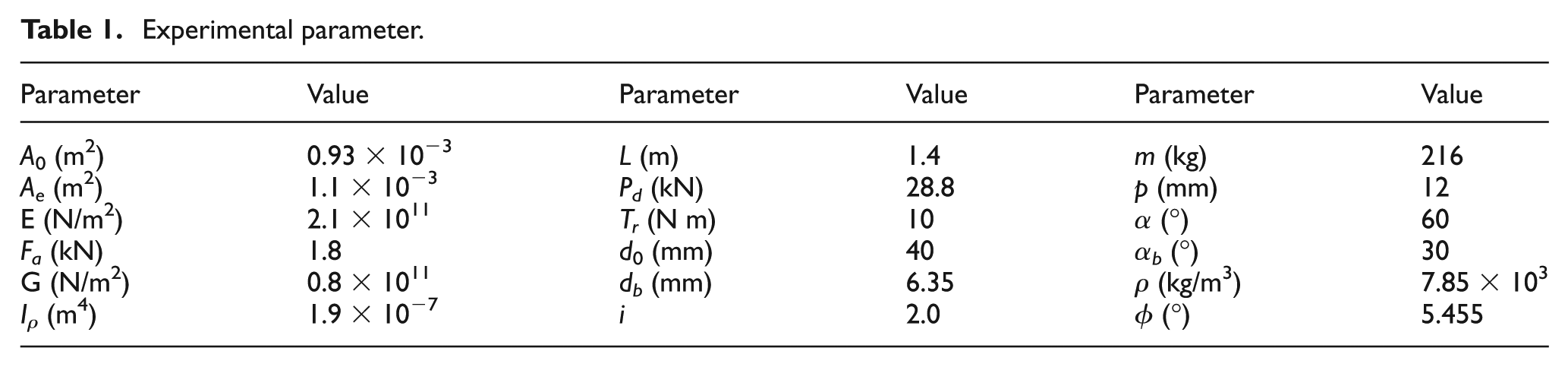
A gantry-type machine tool with a ball screw feed system was used to do the experimental testing, as shown in Figure 3. The worktable was mounted on the bed with a pair of linear guides and driven by a ball screw with a nominal diameter of 40 mm, a pitch of 12 mm and a rated dynamic load Pd of 28.8 kN. The initial preload of the screw nut joints was set as 0.05Pd according to the production manual. The ball screw support bearing units (model: NSK 30TAC 62B) were used at both ends of the screw shaft in the form of DT structure. The linear guides have four ball grooves with a circular arc profile. The parameters of the experimental setup are listed in Table 1.
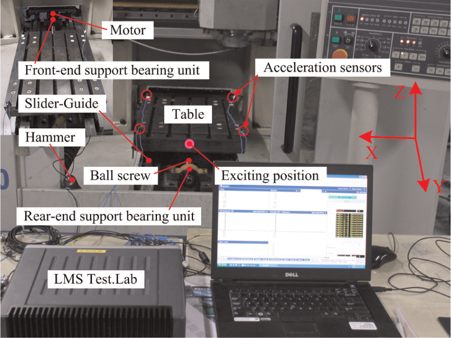
Frequency response testing setup of the ball screw feed system.
Experimental parameter.
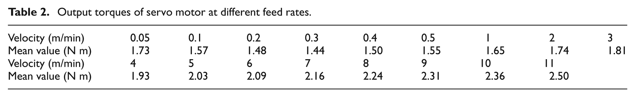
The dynamic characteristics of the feed system at different feed rates were tested using LMS Test.Lab. The acceleration sensors with three directions (model: PCB 356A16) were set on the four corners of the worktable and their sensitivities were calibrated around 100 mV/g, very small difference between each of them. The hammer with a weight of 0.32 kg (model: PCB 086D05) was exerted on one side of the worktable along positive Y-direction and its sensitivity is 0.21 mV/N. The frequency bandwidth is 512 Hz and the number of spectral line is 1024. The acceleration vibration response was acquired and stored by the data acquisition system (model: SCM05). For the test in the static state, the nut was located in the middle of screw shaft and five tests were performed. In motion state, however, the worktable was limited to move in the range of y = [0.5 0.9] in order to reduce the influence of the variation in the tension/compression and torque stiffness. The output torques of servo motor at different feed rates were measured using the module SigmaWinPlus embedded in NC, and the data are listed in Table 2. Meanwhile, the dynamic characteristics of the system were also tested using the spectral testing module of LMS Test.Lab at the feed rates ranging from 1 to 11 m/min with an interval of 1 m/min.
Output torques of servo motor at different feed rates.
Results and discussion
The system natural frequency in static state
Figure 4 plots the average acceleration vibration response for the five tests. The mode shape corresponding to the marked natural frequency (103 Hz) in Figure 4 is shown as the translation along the transmission direction and the natural frequency is determined by both the mass and the transmission stiffness of the system. Therefore, the variation in the system transmission stiffness directly affects its natural frequency.
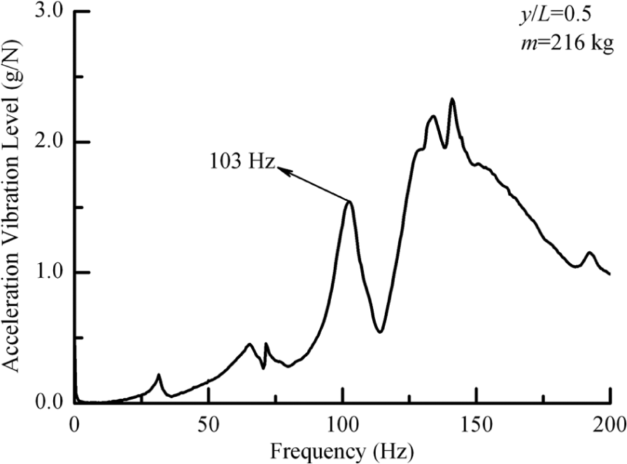
The tested system frequency response in static state.
The system natural frequency in uniform speed state
1. Friction force identification of the feed system
The friction force of the feed system is equal to the output driven force of the servo motor when the worktable moves with a uniform speed. Therefore, it can be expressed as 26
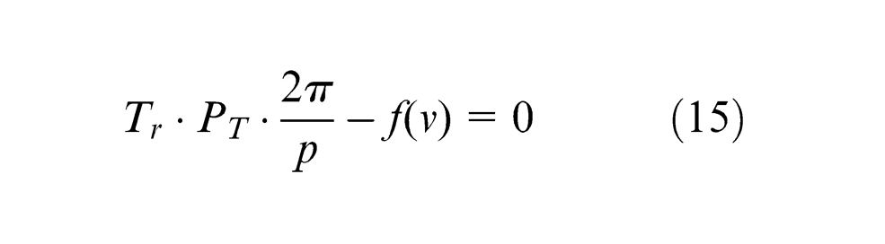
where Tr and PT are the rated torque of servo motor and the output percentage of servo motor rated torque; p is the screw pitch and f(v) is the feed system friction force.
The friction forces calculated by equation (15) at different feed rates are plotted in Figure 5, and then fitted by the model expressed as equation (3). Table 3 lists the associated coefficients of the model.
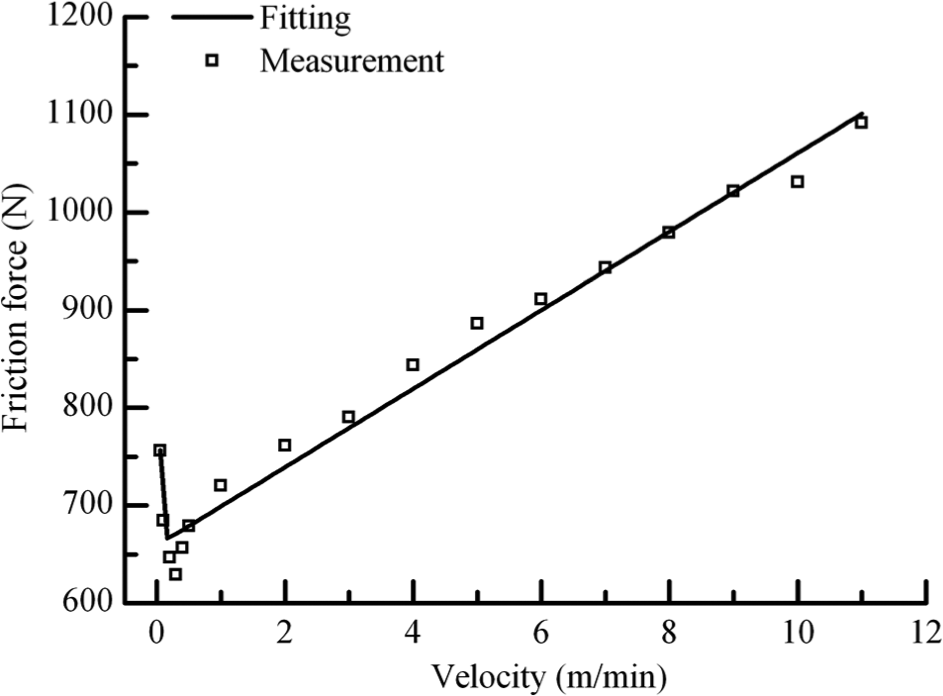
The friction force testing data and fitting curve of the feed system.
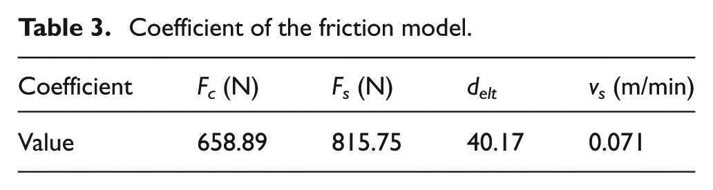
Coefficient of the friction model.
2. The variation in the equivalent axial stiffness of the kinematic joints with feed rate
Based on equations (4)–(6), we can calculate the equivalent stiffness of the screw nut joints and bearing joints at different feed rates, as shown in Figure 6. It can be seen that knut(P, f(v)) and k2by(Fas, f(v)) both increase with the increase in the feed rate, while k1by(Fas, f(v)) decreases with the increase in the feed rate, and it will reduce to 0 when the feed rate of the system reaches 64.65 m/min. This is because the friction force at this feed rate is equal to the pretension force applied on the rear-end support bearing unit joints.
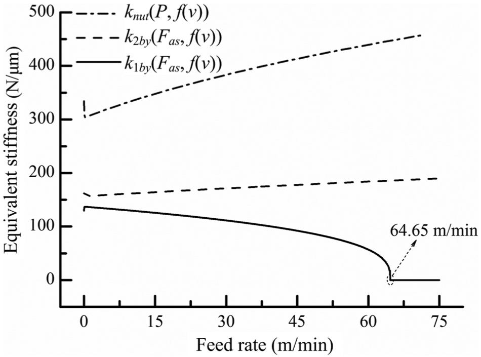
The variation in the equivalent stiffness of kinematic joints with feed rates.
3. The variation in the system natural frequency with feed rate
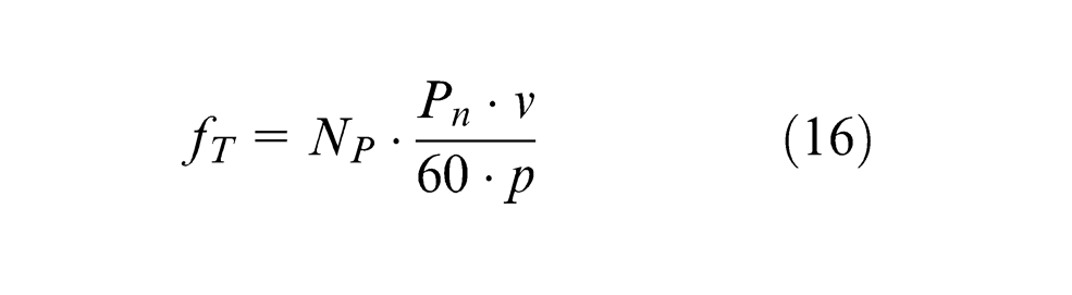
According to the variation in the equivalent axial stiffness of the kinematic joints with feed rate above, the system natural frequency can be calculated by equation (1), as shown in Figure 7. The torque ripple harmonic frequency of the servo motor can be obtained by equation (16) 27 at different feed rates, and the results are also plotted in Figure 7
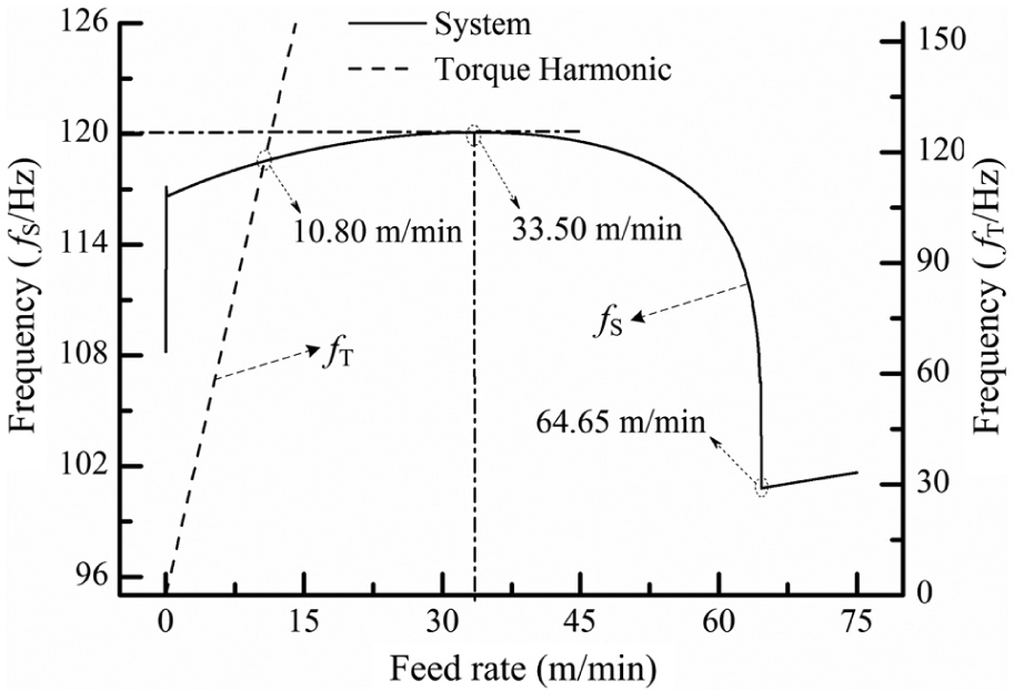
The variation in the frequency with feed rates.
where NP and Pn are the coefficient and pole pair, respectively.
From Figure 7, it can be seen that the system natural frequency increases suddenly from 108 to 117.5 Hz at the beginning of movement due to the sudden change in the friction force. Then the frequency increases slightly with the increase in feed rate and reaches the maximum at the feed rate of 33.50 m/min. After that, the natural frequency rapidly decreases to the minimum at the feed rate of 64.65 m/min owing to the decrease in k1by(Fas, f(v)).
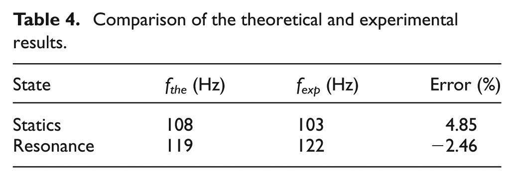
Figure 8 depicts the tested system frequency response at different feed rates. It can be seen that the vibration amplitude of the system is relatively small when the feed rate is less than 10 m/min. A sudden increase of vibration occurs at the feed rate of 11 m/min, which is also called resonance. This is because the harmonic frequency of the torque ripple reaches the same value with the system natural frequency at the feed rate of 10.80 m/min as shown in Figure 7. Table 4 lists the theoretical results (fthe) and the experimental results (fexp) of the system natural frequency in static and resonance state, which indicates an acceptable accuracy of the model proposed.
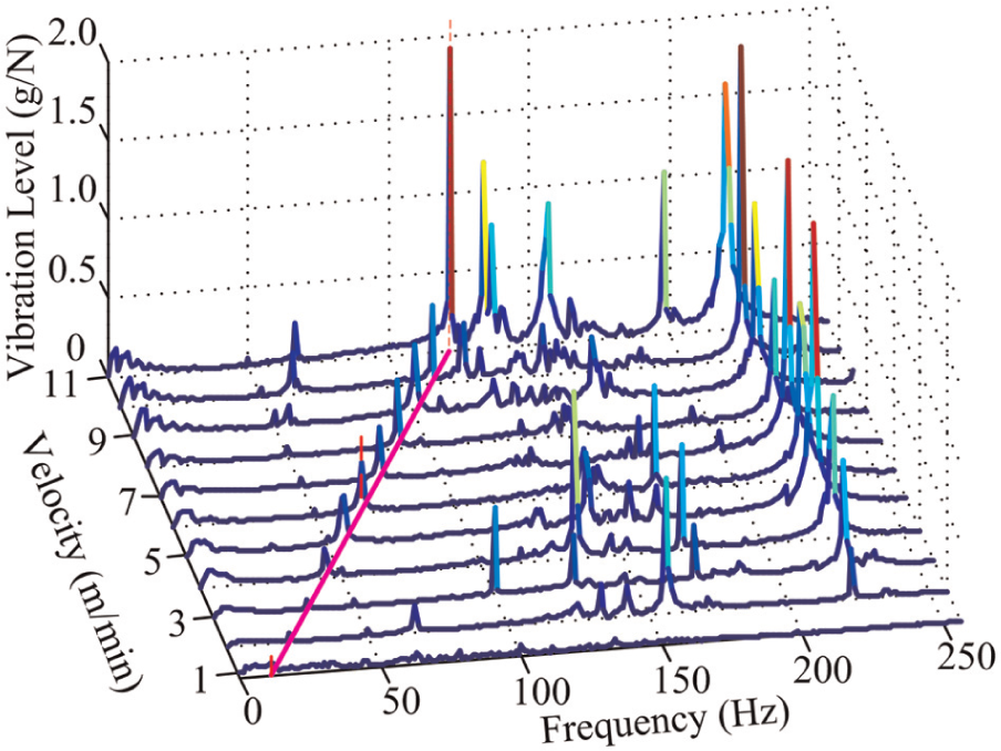
The tested system frequency response at different feed rates.
Comparison of the theoretical and experimental results.
Conclusion
In this article, an equivalent dynamic model of a ball screw feed system was established using hybrid element method considering the influence of the feed rate. The variation in the system natural frequency with different feed rates was analyzed and verified by experiments. The main conclusions are as follows:
The equivalent axial stiffness of the rear-end support bearing unit joints would reduce to 0 when the feed rate of the system reaches 64.65 m/min as a result that the friction force here is equal to the pretension force applied on the rear-end support bearing unit joints.
The system natural frequency increases suddenly from 108 to 117.5 Hz at the beginning of movement. Then the frequency increases slowly with the increase in feed rate and it reaches the maximum at the feed rate of 33.50 m/min. Once the equivalent axial stiffness of the rear-end support bearing unit joints is 0, the system natural frequency would reach the minimum.
Resonance may occur when the system natural frequency is equal to the torque ripple harmonic frequency of the servo motor at the feed rate of 10.80 m/min, which will further affect the system motion accuracy.
The dynamics variation in the feed system with feed rate can provide guidance for the design of the kinematic joints and the feed rate selection of the system.
Footnotes
Appendix 1
Declaration of conflicting interests
The authors declare that there is no conflict of interest.
Funding
This work was financially supported by the key project of National Natural Science Foundation of China (Grant No. 51235009) and National Science and Technology Major Project of the Ministry of Science and Technology of China (Grant No. 2011ZX04016-031).