
Abstract
The tool path composed of consecutive short linear segments (G01 blocks) is still the widespread tool path representation form in five-axis machining. The inherent shortcoming of linear tool path is first-order discontinuity at the corner, which is the bottleneck to achieve high-speed and high-accuracy machining. In this article, a dual-Bézier path smoothing algorithm for five-axis linear tool path in workpiece coordinate system is proposed. There are three steps involved in our method. First, the corner error distribution model is introduced to assign the given tolerance to the smoothing approximation error constraint and the chord error constraint to ensure the interpolation trajectory error within the given tolerance. Second, segment junctions of the linear tool path in workpiece coordinate system are smoothed by double G2 continuous cubic Bézier curves. One cubic Bézier curve is used to round the corner of the tool tip point path, and the other Bézier curve is used to round the corner of the tool axis point path. This algorithm takes the conditions of approximation error constraint, the parameterized synchronization constraint, and continuous curvature constraint into consideration. Hence, the tangency and curvature continuities are both guaranteed in the new path. Third, an adaptive feedrate scheduling method is introduced to interpolate the new path. Simulation and experiment are performed to verify the effectiveness of the proposed method in five-axis tool path smoothing, speed smoothing, and trajectory accuracy controlling.
Keywords
Introduction
Five-axis computer numerical control (CNC) machining is widely used to machine complex curved surface parts, such as impeller, blade, and molds. Compared with five-axis machining in machine coordinate system (MCS), five-axis machining in workpiece coordinate system (WCS) has many virtues. The speed of cutting tool center point can be directly controlled, and the nonlinear error is reduced. Especially, in side milling, it can effectively avoid the overcut and undercut and improve the machining accuracy.
Linear tool path (G01 blocks) is a widespread format for CNC machining due to its high efficiency in approximating complex curvilinear tool paths under predefined tolerance. 1 As shown in Figure 1, commercial CAM software (e.g. CATIA, UG, Cimatron, Master CAM) generates a series of discrete reference points in WCS. Each discrete reference point contains position and direction information of the tool. The position vector describes the tip point trajectory, and direction vector describes the tool orientation. In post-processing software, the cutter locations in WCS are transferred into the NC code in MCS. Then, NC instructions will be sent to CNC system, and CNC system will real-time plan out the position, velocity, and acceleration of each axis under the kinematical constraints of the machine tool. In the linear tool path, at every segment junction, tangency of the tool path is discontinuous. The discontinuity often leads to speed fluctuations and acceleration oscillations. The fluctuations will affect the machine tool movement stability, and be harmful to the surface quality, and decrease the machining efficiency. Although the look-ahead schemes were proposed to alleviate feedrate and acceleration fluctuations,2–4 the discontinuities are still the most important source of feedrate and acceleration fluctuations. Previous research works also show that smoothing consecutive short linear segments with smooth parametric curves is an important method to improve the machining efficiency and quality, such as parametric curves,5,6 Bézier,7–9 B-spline, 10 and non-uniform rational basis spline (NURBS).11,12

Five-axis linear tool path.
Five-axis tool path smoothing mainly includes two categories. One is performed in WCS, in which the continuous motion of the tool is defined by two splines describing the trajectories of the tool tip, and the second point on the tool axis. Siemens840D NC system adopts double NURBS curve for five-axis linkage NC machining instruction format, which can improve the interpolation speed and precision. 13 Langeron et al. 14 utilized dual NURBS tool path with unequal distance (DNTPUD) to describe the five-axis linkage cutting tool path and demonstrated the C2 continuous advantages on improving machining efficiency in comparison with the linear tool path. Bi et al. 15 extended this idea by giving a method to obtain dual NURBS tool path with equal distance (DNTPED). Compared with DNTPUD, DNTPED is more suitable for CNC interpolation calculation, because DNTPED interpolation calculation is more simple and efficient. Fleisig and Spence 16 proposed a method using three C2 continuous splines to describe the tool path. The position spline is a near arc-length parameterized quintic polynomial spline. The orientation spline is a near arc-length parameterized quintic spherical Bézier spline. The third spline was used to synchronize the parameters of the two splines. Koch 17 adopts two B-spline curves to guide tool path for five-axis machining. The tool is guided to move along a first guide path while a further point on the axis of the tool, which is located at a distance from the work portion, is guided along a prescribed second path. The above methods did not consider the effect of the fitting error on tool posture. The implementations of them are so time-consuming that they are difficultly implemented in real-time environment. Beudaert et al. 18 proposed an interesting five-axis local corner rounding method to smooth the tool path in the WCS. The corner rounding method was implemented by blending the junctions in two trajectories that represented the traces of tip center point and a point on the tool axis in the WCS. The curvature continuity was realized by inserting a transition spline curve, and the approximation error was also guaranteed. The orientation parametrization was optimized with the third parametrization spline to smooth the rotational speed. Sneha 19 proposed to insert quintic and septic micro-splines for the tool tip and tool orientation, respectively, at the adjacent linear tool path segments. However, it is mathematically complex to control the synchronization of the position and orientation splines. Shi 1 proposed an on-line path smoothing algorithm using dual Pythagorean Hodograph (PH) curves to blend the corner of the linear tool path. A simple linear synchronization of the position and orientation trajectories is introduced. Although the approximation error of this method can be guaranteed according to the given tolerance, the trajectory error cannot be controlled within the given tolerance because approximation error and chord error cannot be restricted simultaneously.
Another smoothing method is performed in MCS, in which the five movements of the machine tools are divided into translational movement and rotational movement. Both Fanuc 20 and Heidenhain 21 NC systems introduce the spline interpolation function using five parameter curves to describe the trajectories of five axes in MCS. It proves that smoothing the linear path in MCS is also an effective means to improve the machining quality and machining efficiency. Using the quaternion interpolation scheme, Ho et al. 22 smoothed the tool orientation to reduce the cutting error. Tutunea-Fatan and Feng 23 proposed a dual-spline tool path smoothing algorithm in the MCS. The method fitted a three-dimensional (3D) B-spline for the three translational joints and fitted a two-dimensional (2D) B-spline for two rotational joints. The synchronization of the five machine joints was achieved using the same knot sequence in the two fitting processes. Yuen et al. 24 proposed a smooth spline interpolation for five-axis machining, in which the smoothed positional and rotational movements are represented by quintic splines. The nonlinear relationship between spline parameters and displacements along the path is approximated with ninth-order and seventh-order feed correction splines for position and orientation, respectively. This method decreases tracking error for each axis in machine tools. Beudaert et al. 25 proposed a five-axis tool path smoothing method by taking the drive constraints, such as maximum speed, acceleration, and jerk, into consideration. It can increase the average feedrate effectively. Bi et al. 26 presented a G2 dual-Bézier corner transition algorithm. One Bézier curve is used to blend the segment junction of the translational path, and another Bézier curve smoothes the segment junction of the rotational path. The linear synchronous mechanism is used to guarantee the parameterized synchronization of the translational axes’ path and the rotational axes’ path. In the above methods, the trajectory error cannot be controlled within the permissible maximum error range because approximation error and chord error cannot be restricted simultaneously.
To satisfy the requirements of high-speed and high-accuracy five-axis machining, this article proposes a G2 dual-Bézier path smoothing algorithm based on the corner error distribution model. To guarantee the interpolation trajectory error within the given tolerance, the corner error distribution model is introduced to assign the given tolerance to the smoothing approximation error constraint and the chord error constraint. Then, segment junctions of the linear tool path in WCS are rounded by two G2 continuous cubic Bézier curves. One cubic Bézier curve is used to round the corner of the tool tip point path, and the other Bézier curve is used to round the corner of the tool axis point path. This algorithm takes the conditions of approximation error constraint, the parameterized synchronization constraint, and continuous curvature constraint into consideration. Hence, the tangency and curvature continuities and interpolation trajectory error within the given tolerance are guaranteed in the new path. The comparison of our method with those available in the literatures is presented in Table 1.
Comparison of path smoothing methods.
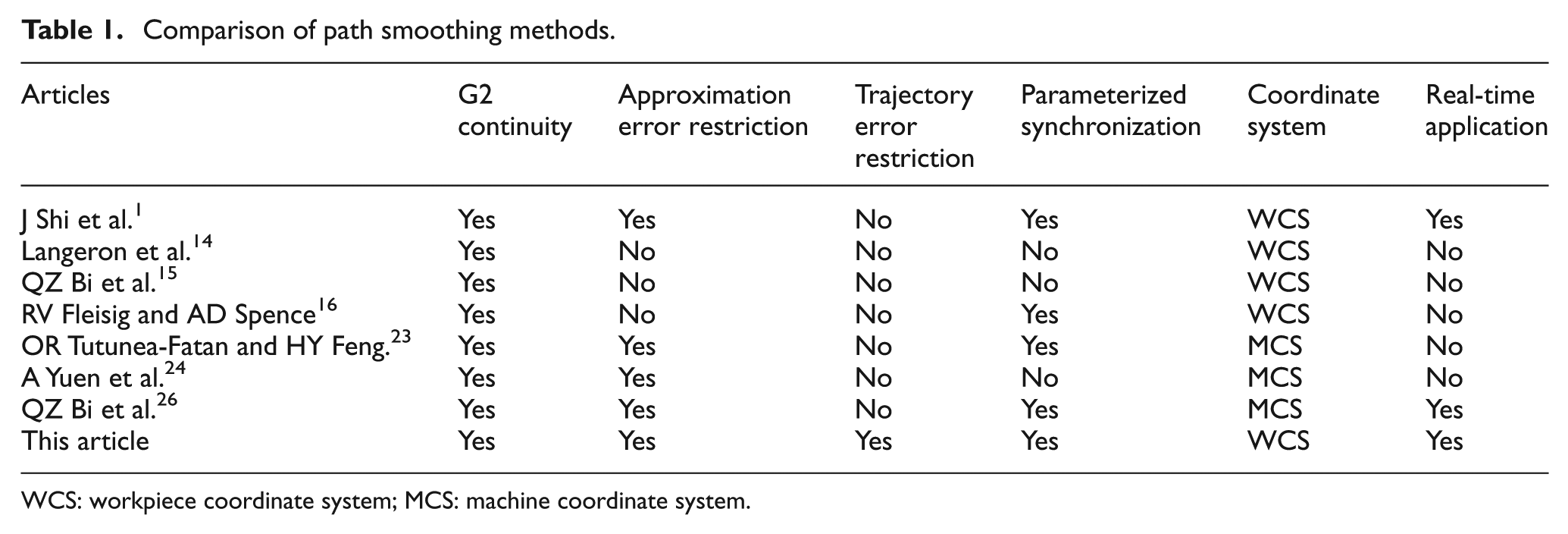
WCS: workpiece coordinate system; MCS: machine coordinate system.
The remainder of this article is organized as follows: section “Definition of the corner error distribution model” describes the corner error distribution model in WCS. Dual-Bézier path smoothing algorithm is given in section “Dual-Bézier path smoothing for five-axis linear path in WCS.” In section “Interpolation method for five-axis continuous tool path in WCS,” an adaptive feedrate scheduling method is introduced to interpolate the new path. Simulation and experiment are presented in section “Simulation and experiment.” Section “Summary and conclusion” concludes this article.
Definition of the corner error distribution model
When path smoothing algorithm and parametric interpolation algorithm are utilized to interpolate the linear tool path, approximation error and chord error may occur. They are the main error sources causing trajectory error. The given tolerance
In the existing studies,1,5–12,14–25 approximation error and chord error are calculated, respectively, and they are all restricted with the given tolerance value
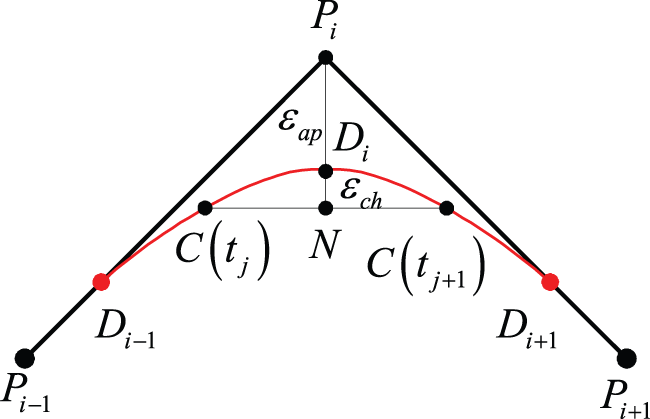
Definitions of approximation error and chord error.
Definition of three-axis corner error distribution model
As shown in Figure 2, two line segments are defined by three points Pi−
1, Pi
, and Pi
+1. Assuming that segment junction is rounded with a curve C(t), the maximum approximation error is

Assuming that the maximum curvature of the transition curve C(t) is

According to Bi et al.,
8

Definition of five-axis corner error distribution model
As shown in Figure 3, the discrete cutter posture in WCS is defined


Five-axis linear tool path and corner rounding curve.
To guarantee the trajectory error of the tool axis, the errors of the tool tip point, the tool axis point, and the tool axis should be restricted as follows


The maximum transitional velocity of the tool tip point is expressed as

The maximum transitional velocity of the tool axis point is expressed as
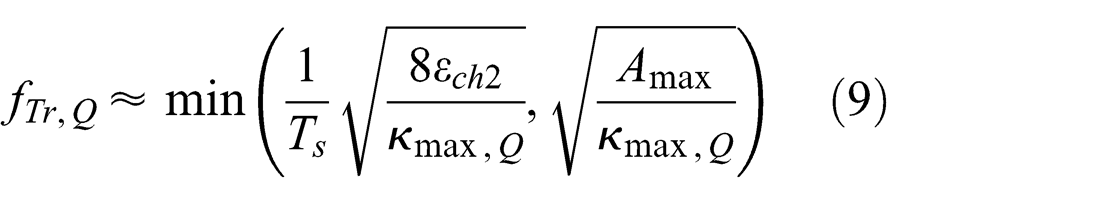
In order to obtain maximum transitional velocity, the maximum approximation errors and the chord errors should be calculated as
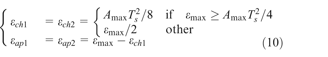
The approximation errors
Dual-Bézier path smoothing for five-axis linear path in WCS
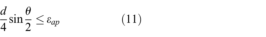
In our previous works, 8 a corner smoothing method for three-axis linear tool path based on cubic Bézier curve was introduced, which can restrict the approximation error exactly, as shown in equation (11). In this section, G2 continuous dual-Bézier transition algorithm is proposed for five-axis linear tool path in WCS. One Bézier curve rounds the corner of the tool tip point path, and another Bézier curve rounds the corner of the tool axis point path. Parameter synchronization between the tip point trajectory and tool axis point trajectory, approximation error constraints, and transition length optimization is taken into consideration
where the transition length d is defined as the length of the linear segment that is replaced by the transition curves and
Definition of five-axis dual-Bézier curve
A shown in Figure 3, five-axis linear tool path is defined by two linear trajectories. The tip point trajectory with dots sequence is defined as
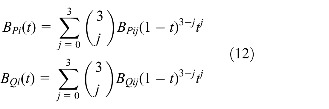
where t is the Bézier parameter;

The synchronization of parametrization of two smoothed curves is crucial in the smoothing of five-axis path. If the linear interpolation method is used, the two continuous trajectories between two reference points are defined as 1

The continuous movement trajectory of tool axis along the linear trajectories

The continuous movement trajectory of tool axis along the dual-Bézier transition curves is expressed

According to equations (15) and (17), continuous path of tool axis is a ruled surface. The deviation between smoothing tool path ruled surface and the original linear path ruled surface is the maximum approximation errors of corner transition.
Synchronization of parameterization
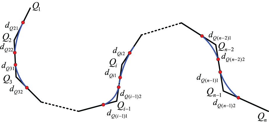
The synchronization of parameterization of two smoothed curves is crucial in making sure that the variation in the tool axis direction is continuous and is the most important constraint in the tool path smoothing. As shown in Figure 3, the corner of the segments

Equation (18) can be represented as

Approximation error constraint
According to equation (11), the approximation error of the tool tip point curve
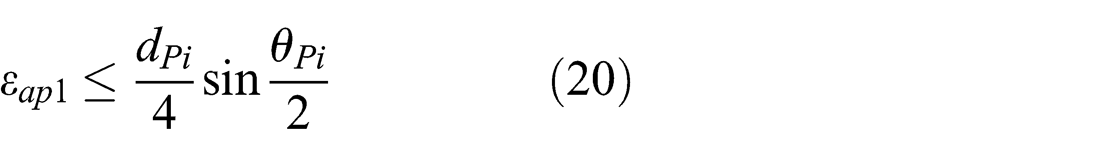
where
The approximation error of the tool axis point curve
where
Real-time G2 path smoothing
The smoothing methods for five-axis linear tool path linear need to take curvature-continuous constraint, the approximation error constraint, and the synchronization of parameterization into consideration. According to equations (19)–(21), approximation error and synchronization constraints can be accomplished by designing the transition lengths. As shown in Figure 4, the transition lengths of two adjacent segments also need to meet the constraints of the corresponding line segment lengths

Corner rounding for the point on tool axis.
The transition length of the first segment meets
According to equation (19), to meet the tool tip point and the tool axis point synchronous constraint, the transition lengths need to satisfy the following relations
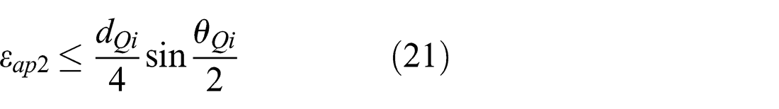
According to equations (20) and (21), in order to meet the approximation error constraints

Equation (22) is simplified, and the transition length is less than half the length of the corresponding line. The key parameters of the transition curves can be gained
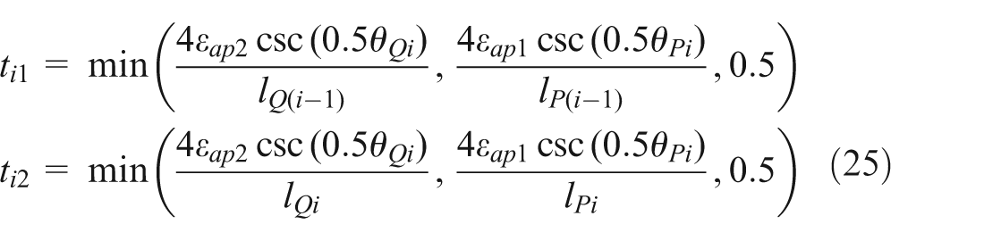
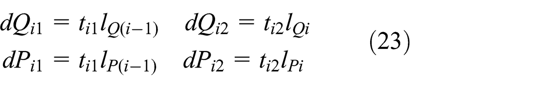
Substituting
The control points for Bézier curve
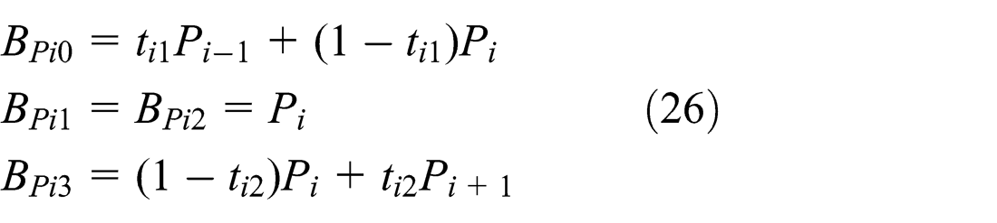

Substituting equations (26) and (27) into equation (12), Bézier curve
Substituting equations (26) and (27) into equation (13), it is proved that the tangency of the smoothed path is continuous

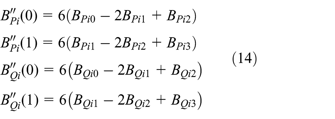
Substituting equations (26) and (27) into equation (14), the second derivatives of the curves

Then, the curvatures of the curves
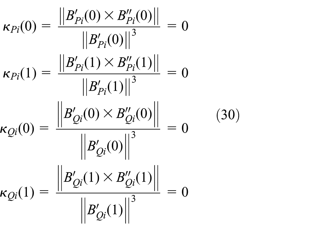
According to equation (30), it is proved that the curvature of the smoothed path is continuous. So the smoothed path is G2 continuity.
Interpolation method for five-axis continuous tool path in WCS
For five-axis dual-spline interpolation, a real-time adaptive feedrate scheduling method considering the comprehensive constraints is proposed. First, the comprehensive constraints (such as the chord error constraint, the maximum normal acceleration, the servo capacity of each axis) are deduced to obtain the maximum feed and feasible acceleration range. On this basis, the bi-directional scanned feed scheduling method is given.
Comprehensive constraints’ computation
Constraints of chord error and the maximum normal acceleration
Based on the corner error distribution model, the constraints of chord error and the maximum normal acceleration are calculated by


where
Constraints of the servo capacity
In interpolation process, when the input command of the axis exceeds its servo capability, the tracking error will increase. Therefore, the servo ability of each axis should also be considered when the feed scheduling is implemented.
However, in CNC system, the constraints of the servo capacity of each axis are defined in MCS. The key point of five-axis interpolation in WCS is to transfer the constraints of the servo capacity to the constraints for motion of tool in WCS. These mapping relations are deduced as follows:
1. The feed and acceleration of machine tool

The coordinate of machine tool is

Assuming that a given kinematics inverse transformation for five-axis machine tool is
The speed of the axis
where
The acceleration of the axis

where
2. The maximum feed constraint of machine tool
The maximum feed of axis Λ is V Λm . The following equation is obtained
The feedrate of the tool tip is restricted by

3. The maximum acceleration constraint of machine tool
Assuming that acceleration limit ranges for axis Λ are [−a
Λm
, a
Λm
], velocity constraint polygon is surrounded by groups of five pair parallel lines, green area in Figure 5. Restricted by the maximum acceleration of each axis, the feedrate constraint


where


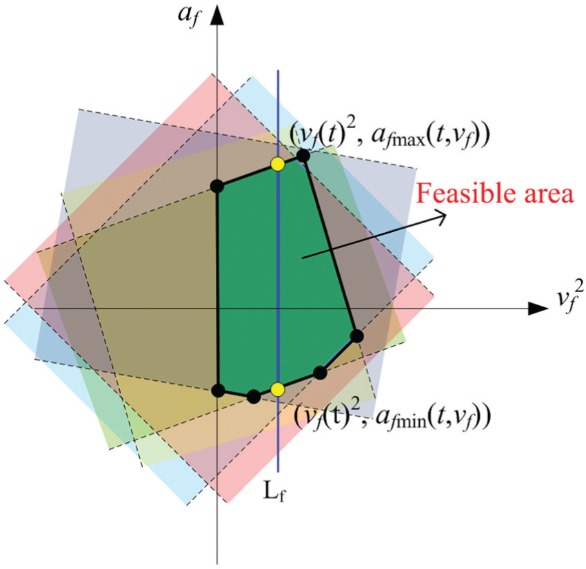
Feasible polygon determined by axis acceleration constraints.
4. The maximum feed and acceleration restricted by comprehensive constraints
The maximum feed

The feasible acceleration of the tip point is expressed as equation (40) or (41).
Adaptive feedrate scheduling
In five-axis parametric curve interpolation in WCS, tool tip point is usually selected to implement feedrate planning. The optimal feedrate of tool tip point is gained by considering various constraints and adopting the bi-directional scanned feed scheduling method. The increment of arc-length of the tool tip point curve is calculated and the parameter is estimated. Then the coordinate of the tool tip point is obtained. According to the parameters of synchronous mechanism, the tool axis direction is also obtained. Finally, using kinematics inverse transformation, the command position of each axis in MCS is gained.
As shown in Figure 6, the bi-directional scanned feed scheduling method based on the look-ahead window consists of two functions: the reverse scanning to generate limit feed curve and the forward scanning to obtain adaptive feedrate.

Adaptive feed scheduling with a look-ahead window.
Reverse scanning
A look-ahead window is employed here. The window covers a set of linear segments, the number of which is dependent on the CPU’s power. At the beginning of the task, N linear segments are pushed into the look-ahead first-in first-out (FIFO) buffer from the decoding shared memory.
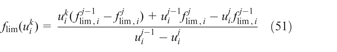
First, using the five-axis corner error distribution model, the optimization error constraint values are obtained,
When the ith segment curve is being scanned, the accumulative arc-length, the parameter, the feed limitation, and the acceleration limitation of jth sampling period are defined as
To solve the problem of cross section of deceleration, the cumulative arc-length criterion is defined as

Reverse scanning process is as follows:
Let
If
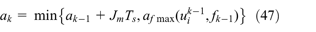
2a.Applying jerk-limited S-shape acceleration 27 and considering the maximum feasible acceleration constraint, the acceleration of the jth reverse feed point is calculated as follows

where the jerk limit Jm
is predefined as a fixed value by CNC system.
2b.The jth reverse feed is evaluated as follows

2c.The parameter

If
2d.Comprehensive constraints are calculated as

First, compare
Let
Forward scanning
Forward scanning is performed from the start of the look-ahead window to the end of the look-ahead window. Forward scanning generates optimal feedrate profile using jerk-limited acceleration method and generates the interpolating point.
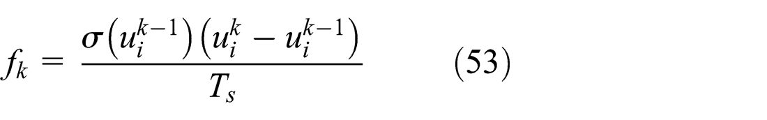
For the kth sampling period, the accumulative arc-length, the sequence number of curve, the parameter, the feedrate, and the acceleration are denoted as (lk
, i,
Step 1. The feedrate is initialized by setting
Step 2. Jerk-limited acceleration method is utilized to evaluate the feed of kth (
The acceleration of kth sampling period is calculated using equation (40)
Then, the feed of kth sampling period is evaluated as

Step 3. The parameter

If
Step 4. After obtaining
First, two adjacent reverse feed points
If

Step 5. After obtaining the feedrate

Adjust the optimal feedrate within reverse feed limit.
The tool pose in WCS is expressed as

The coordinate of each axis in MCS is obtained
Finally, the motion command for each axis is updated in programmable motion controller.
Simulation and experiment
In this section, simulation and experiment are performed on a five-axis machining center with dual rotary tables, as shown in Figure 8. The in-house developed research CNC, which is PC-based, has an open architecture and allows rapid implementation of the proposed interpolation algorithm. The kinematics inverse transformation

where
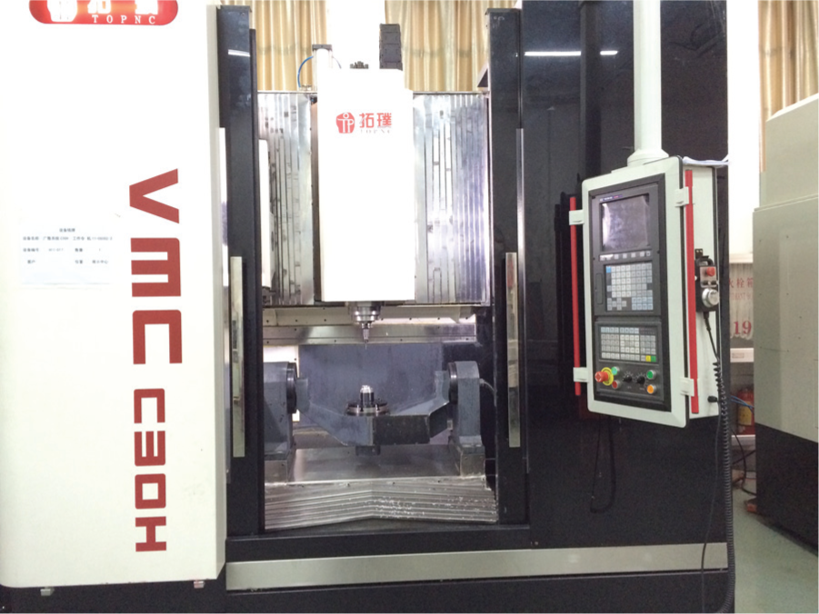
VMC-C30 five-axis machining center.
This experiment demonstrates the advantages of the proposed algorithm by machining a polyhedron workpiece, as shown in Figure 9. In the experiment, the drive constraints of each axis are listed in Table 2. The maximum jerk is set as 8.1 × 108 mm/min3. The maximum normal acceleration is set as 1.08 × 106 mm/min2. The command feedrate is set to 1500 mm/min and the sampling period Ts is 0.004 s. The maximum look-ahead N of blocks is set as 50, and the predefined tolerance error is set as 0.02 mm.
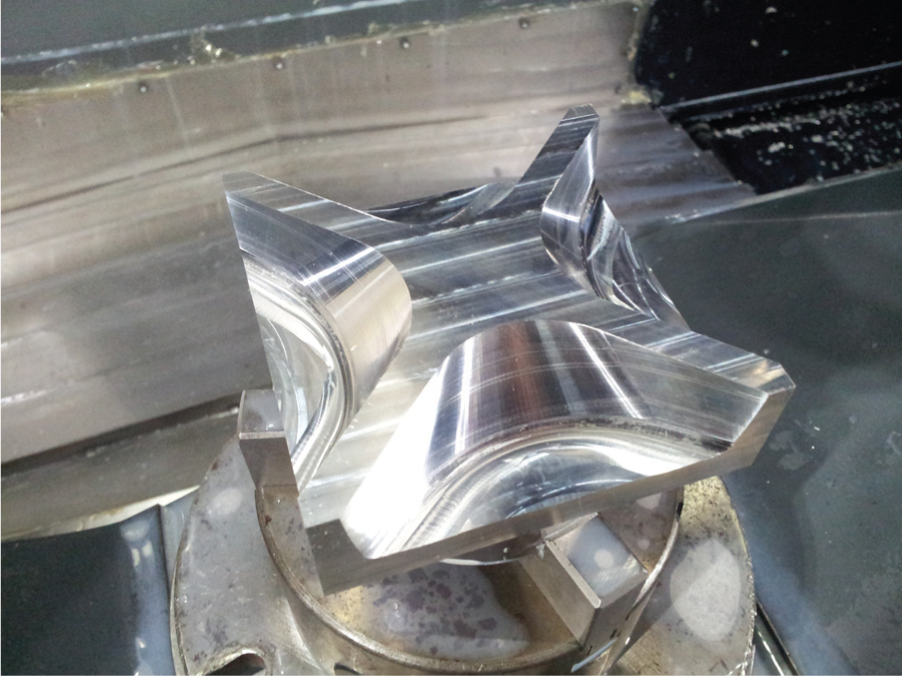
Polyhedron workpiece.
Machine tool driving constraints.

First, the approximation error constraint and the chord error constraint are calculated:
A side milling tool path for polyhedron is taken for example to demonstrate dual-Bézier path smoothing algorithm presented in section “Dual-Bézier path smoothing for five-axis linear path in WCS.” The approximation error constraint value is set to 0.0194 mm. The generated G2 continuous tool path is shown in Figure 10.

Dual-Bézier tool path for the side milling of the polyhedron.
According to Figure 11, in the new smoothing path, the trajectory of the tool tip point is curvature-continuous. There are three peaks of the curvature, corresponding tags in Figure 11, which are in conformity with the locations on the polyhedron parts’ computer-aided design (CAD) model. The points marked with ① and ② are where the surface curvature change is bigger. The point marked with ③ is retract of the side milling.
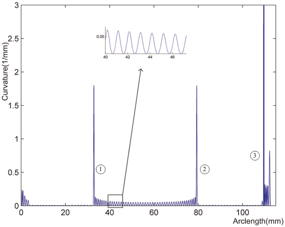
Relationship of curvature and arc-length for the new tool tip point path.
Figure 12 shows three types of error profiles for the trajectory generated by the proposed method. The trajectory error, the chord error, and the approximation error are all less than or equal to the predefined tolerance 0.02 mm.
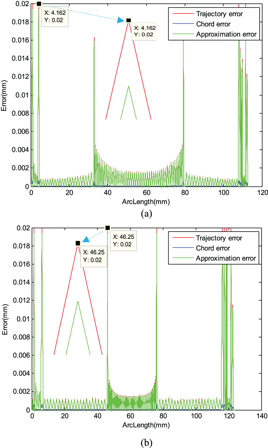
Errors of the tool tip and tool axis point based on error distribution model: (a) three types of error of the tool tip point and (b) three types of error of the tool axis point.
In the existing studies,5–12,14–25 approximation error and chord error are calculated, respectively, and they are all restricted with the predefined tolerance usually. Take Shi’s 1 method, for example, as shown in Figure 13, the chord error and the approximation error of the trajectory satisfy the predefined tolerance constraint, but the trajectory error exceeds the predefined error. The maximum trajectory error of tool tip point reaches 0.02048 mm, and the maximum trajectory error of tool axis point is 0.02062 mm. They are all bigger than the predefined tolerance of 0.02 mm. According to Figure 13, we find that the point whose trajectory error exceeds the predefined error is the point with bigger curvature. Thus, the proposed algorithm is useful to control the trajectory error at the corner of the linear path.
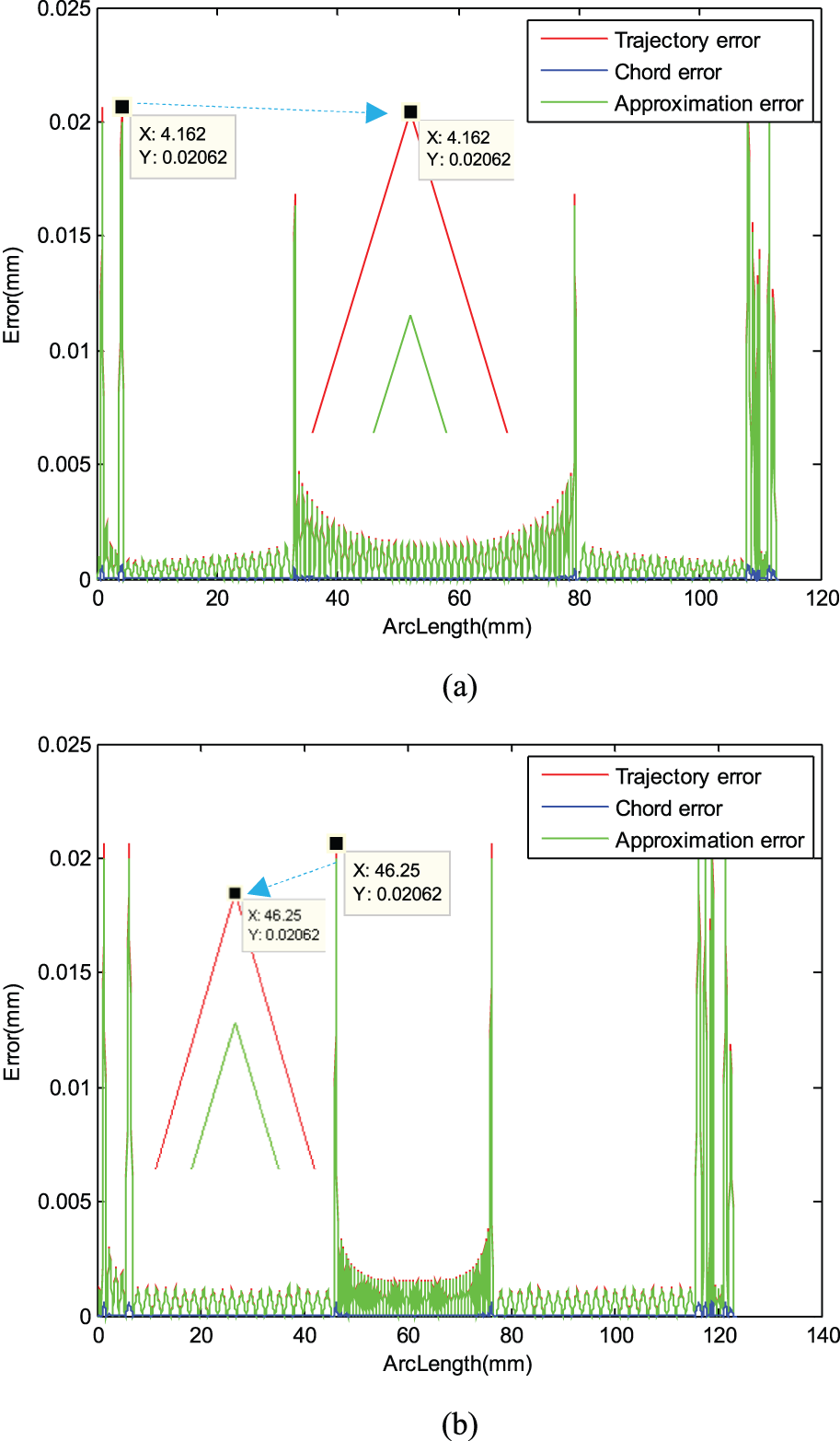
Errors of the tool tip and tool axis point without error distribution model: (a) three types of error of the tool tip and (b) three types of error of the tool axis point.
As shown in Figure 14(a) and (b), the feedrate and acceleration of tool tip have few fluctuations, which just appear at the corners with big angles of the linear tool path. The feedrate profile obtained with the proposed feedrate scheduling method is smooth, and the feedrate is close to the command feedrate 1500 mm/min. Because the speed of C-axis reaches the limitation 2000°/min at the middle, as shown in Figure 15(a), the feedrate of the tool tip point slows down at the middle part.

Speed and acceleration of the tool tip point: (a) tool tip feedrate and (b) tool tip acceleration.

Speed and acceleration of each axis: (a) speed of each axis and (b) acceleration of each axis.
From the analysis presented above, it can be found that the new tool path generated by the proposed path smoothing algorithm for five-axis linear tool path is curvature-continuous. In addition, the trajectory error, the chord error, and the approximation error are all guaranteed within the predefined tolerance. Based on smoothing the tool path, considering the comprehensive constraints and utilizing jerk-limited acceleration method, the feedrate and acceleration fluctuations are alleviated.
Summary and conclusion
The most widespread tool paths are represented linear segments (G01 blocks) to approximate the complicated surface in machining. The discontinuities at the corners are the main obstacle to perform high-speed and high-accuracy machining.
In this work, a dual-Bézier path smoothing algorithm for five-axis linear tool path in WCS is proposed. First, the corner error distribution model is presented to guarantee the trajectory error, the chord error, and the approximation error within the predefined tolerance. Second, every junction of the five-axis tool path is blended by inserting two cubic Bézier curves to generate a curvature-continuous tool path; moreover, the tool tip point curve and tool axis point curve are parameterized synchronous. Third, a real-time adaptive feedrate scheduling method considering the comprehensive constraints is presented. Compared with the previous methods, the novel path smoothing algorithm has the following advantages: (1) the tool tip point curve and tool axis point curve are parameterized synchronous, (2) the smoothed tool path is everywhere curvature-continuous, (3) the trajectory error is guaranteed within the predefined tolerance, and (4) the feedrate and acceleration fluctuations are alleviated.
The proposed dual-Bézier transition algorithm has been integrated into an open five-axis CNC system. The experiments are carried out to test its practicability and effectiveness. The interpolator integrated with the dual-Bézier corner transition algorithm guarantees the trajectory accuracy and generates smooth speed and acceleration curves.
Footnotes
Academic Editor: ZW Zhong
Declaration of conflicting interests
The authors declare that there is no conflict of interest.
Funding
The authors gratefully acknowledge the financial support of the National Natural Science Foundation of China (No. 50875171) and the National High-Tech Research and Development Program of China (No. 2009AA04Z150).