
Abstract
It has been generally recognized that it is very important for industrial users to test the performance of high-accuracy numerical control machine tools before ordering them. Methods based on special devices such as Double Ball Bar and R-test are currently used for kinematic error measurement and compensation of five-axis machine tools. However, these methods need special devices and software, and industrial machine tool users prefer testing machine tools by physically machining a special workpiece, due to its simplicity and intuition, as doing such machining tests are just like manufacturing parts in real production. On the other hand, since existing machining tests such as cone frustum test piece fail to reflect the dynamic performance of five-axis machine tools, it has drawn a lot of attention to the development of a new machining test method to address this issue. This article introduces a new machining test standard that has been proposed for testing the accuracy of five-axis machine tools using an S-shaped test piece. This method has already been accepted by the International Standard Organization and is now under development for inclusion in ISO 10791 Part 7. The advantages of the S-shaped test method in testing machining performance of five-axis machine tools are analyzed and demonstrated in this article. Furthermore, new development has been made to simplify the definition, reduce the testing workload and improve the measurement accuracy of the proposed testing method.
Introduction
During the past decades, five-axis computer numerical control (CNC) machine tools have been widely applied in the automotive and aerospace industries, where many parts with complex geometry are defined by sculptured surfaces. 1 Five-axis machine tools combine movements in both linear and rotary axes, and it is very important to effectively measure and test the machining accuracy of such machine tools when they have been built and installed. For a typical five-axis machine tool, there are 21 geometric errors in the three linear axes and 12 geometric errors in the two rotary axes. These errors will significantly influence the accuracy of machined parts. Before the machine tool users make a final decision to purchase a five-axis machine tool, a number of tests should be done to ensure that the machine tool has been properly prepared for production use. International Standard Organization (ISO) 10791-1, 2, and 3 standards (ISO 10791:1998 series) 2 describe the measurement methods to evaluate static positions and orientation errors of rotary axes. There are also a number of devices and methods proposed for identifying the linkage errors of five-axis machine tools. Although these methods need special devices and software packages, the end users of five-axis machine tools prefer just to use machining tests to evaluate the machining accuracy, since it is simple and intuitive, as it just needs to machine a part and measure it, which is what the users do in real production.
So far, there are no five-axis machining tests introduced by ISO. The only well-known machining test standard uses a cone frustum test piece, which was introduced in the National Aerospace Standard (NAS) 979 3 in 1969. As it is the only standard well known in industry describing a five-axis machining test, it has been widely accepted by machine tool manufacturers and end users as an acceptance test piece. However, users of this standard found that five-axis machine tools which even passed the NAS test may still not satisfy the requirements for machining free-form surfaces in actual industrial applications for the reason that the movements about the rotary axes following the tool paths of this test are smooth which cannot reflect the dynamic performance of the five-axis machine tools. An S-shaped test piece 4 was proposed as a new standard to overcome the disadvantage and was discussed at the ISO/TC39/SC2 74th meeting. This proposal was then accepted by ISO/TC39/SC2 as an additional machining test for the acceptance of five-axis machine tools by users, after voting by delegates from different countries.
The original version of the S-shaped test piece was proposed by Chengdu Aircraft Industrial Company as the final test for the acceptance of five-axis machine tools 5 before ordering them. After that, more and more five-axis machine tool users and manufacturers adopted this test piece for testing the dynamic performance of five-axis machine tools. One of the national science and technology major projects of China, which aimed to address this issue in support for the Chinese machine tool manufacturers for improving their development ability, adopted this machining test as the final test for the acceptance of newly developed five-axis machine tools in that project. The authors of this article were members of the technical team of this major project and were responsible for leading the development of five-axis machine tools. To make sure all developed machine tools under that project satisfy the requirement of users, the S-shaped test piece was selected and re-defined to address the acceptance for production use.
This article introduces the development progress of this new standard and analyzes the advantages of the S-shaped test piece in testing the five-axis machine tool performance which were affected by geometric errors of the machine tool and dynamic characteristics related to the CNC system. The rest of this article is organized in four sections. Section “Review of machine tool testing methods” gives a literature review of existing testing methods for five-axis machine tools. Section “Characteristics analysis of the S-shaped test piece” introduces the development progress of the S-shaped test piece standard. Section “Latest development of the proposed standard” analyzes the characteristics of the S-shaped test piece, and section “Conclusion” gives the conclusion.
Review of machine tool testing methods
Previous efforts have been made to establish methods to test the accuracy of five-axis machine tools. These methods can be categorized into three types: (1) kinematic error measurement and compensation based on special measuring devices, (2) machining performance detection based on machining tests, and (3) machining accuracy estimation of specified parts based on measured geometric errors of five-axis machine tools.
Kinematic error measurement and compensation based on special measuring devices
Double Ball Bar (DBB) and R-test devices are most widely used for identifying kinematic errors of five-axis machine tools. Abbaszadeh-Mir et al. 6 reported their attempt for identification of the link geometric errors of five-axis machine tools using DBB tests. DBB test is based on the following theory: if a CNC machine is programed to trace a circular path and the positioning performance of the machine is perfect, then the actual circle would exactly match the programed circle. However, in practice, many factors in the machine tool geometry, its control system and wear can affect the radius of the test circle and its shape to deviate from the programed circle. Such measured deviation along specified circle paths with the rotary axis is taken to calculate the linkage geometric errors. Tsutsumi and Saito 7 presented their method to identify and compensate systematic deviations of five-axis machine centers based on DBB tests. Another method to identify kinematic errors based on R-test was proposed by Bringmann and Knapp. 8 The three-dimensional displacement of the sphere attached with the spindle can be measured using a nest of three (or more) linear displacement sensors. The sphere center is programed such that it stops at the start location when the rotary axes are moving. However, displacements of the sphere could be measured due to the geometric errors and linkage errors of the machine tool. The displacements of the sphere could be taken to calculate the systematic errors. Ibaraki et al. 9 introduced a method to construct an error map of rotary axes on a five-axis machining center based on static R-test. Some researchers also tried to use the on-the-machine probing system for kinematic error measurement. Erkan and Mayer 10 published their work on a cluster analysis applied to volumetric errors of five-axis machine tools based on the on-the-machine probing system. Tracking interferometer is also applied to address this issue, for example, Schwenke et al. 11 proposed a method of linear and rotary axes calibration based on tracking interferometer. Such device-based methods were adopted by ISO standards to help identify and compensate geometric errors of five-axis machine tools. However, dynamic performance test of five-axis machine tools seems to have been ignored.
Machining performance detection based on machining tests
Methods based on special measuring devices are important for evaluating kinematic errors. However, typical machine tool users show more interests in estimating machining errors using measuring methods based on machining tests due to their convenience. Since there are no five-axis machining tests introduced by ISO, many researchers proposed various machining tests to measuring kinematic errors for five-axis machine tools. A cone frustum test piece was introduced in the NAS 979 3 in 1969. As it is the only standard well known in industry describing a five-axis machining test, it has been widely accepted by machine tool builders and end users as test piece for acceptance. In addition to the NAS test, there are several machining tests proposed for five-axis machine tools by other researchers, including the Numerical Control Gesellschaft (NCG) test, 12 the regular square truncated pyramid test, 13 and a set of tests proposed by Ibaraki et al. 14 However, machine tool users show little interests in these new tests due to the following reasons: the NCG test is too complicated to be a test piece for acceptance. It may take several hours to finish this test. The square truncated pyramid test shows no advantage over the NAS test. The movements of the machine tool in this test show no much difference compared to the NAS test, and the Soichi’s tests are only applicable to kinematic error identification of machine tools with rotary tables. Therefore, the NAS test is still the most widely accepted test piece in industry. However, some experiments show that machine tools which passed the NAS 979 test still cannot satisfy the requirement of the ruled surface machining in actual production. The reason is that the movements about the rotary axes following the tool paths of this machining test are smooth. On the contrary, the movements about the rotary axes following the tool paths when machining real parts always have sharp changes which require high dynamic performance of the five-axis machine tool.
Machining accuracy estimation of specified parts based on measured geometric errors
Many researchers also tried to construct the relationship between the geometric errors of five-axis machine tools and the machining accuracy of a specified part. Callaghan 15 proposed a method for evaluating the machining ability of machine tools when machining a specified part with given tolerance based on machine tool configurations and measured geometric errors. Li et al. 16 proposed a dynamic feature information model for integrated manufacturing planning and optimization which could be regarded as an information model for integrating the machine tool performance and machining accuracy of a given part. Their previous work 17 proposed a method to guarantee feature recognition of complex parts. These technologies may significantly help the machine tool users to recognize whether a five-axis machine tool is good enough for machining a specified part. More work is still to be done due to inadequate technology maturity for applications in a shop floor, as there is still no commercial software that has been developed for end users.
As discussed above, all of the existing methods are still inadequate on effectively testing the machine tool performance combined with geometric accuracy and dynamic machining performance. It is required by industrial users to propose a new test piece to evaluate the comprehensive machining performance of five-axis machine tools which could be taken as a test for acceptance by machine tool users before they decide to order and begin production with the new machine tools.
Characteristic analysis of the S-shaped test piece
With the efforts of the authors’ working group, the S-shape test piece was optimized for the use as a standard. As the representative of ISO in China, Mou 4 presented the proposed S-shaped test piece as a new standard to address the issues discussed above, and the proposal was discussed and accepted by ISO/TC39/SC2 at the ISO meeting held in Sandviken, Sweden, in September 2012. Details of the new test such as test piece definition, machining process, and measuring requirement are introduced in the study by Mou et al. 5 As a new machining test standard, the S-shaped test piece shows clear advantages in testing machining performance of five-axis machining tools compared with the NAS 979 test. However, as its geometric definition is more complicated, the measurement of the S-shaped test piece seems more difficult. The following sub-section gives characteristic comparison of these two types of test pieces.
Comparison of movements about rotary axes following tool paths
Figure 1 shows the tool paths of two machining tests. Take a typical five-axis machine tool with two rotary axes (C-axis and A-axis) in the spindle side as an example; the movements about the rotary axes following the tool paths are shown in Figure 2. As can be seen from Figure 2, movements about the rotary axes following the tool paths for NAS test are smooth without any sharp changes of feed rate. In contrast, there are several big sharp changes of the movements about the rotary axes for the S-shaped test piece which can reflect the dynamic performance of the five-axis machine tool. This is the main reason that most experts of ISO/TC39 agreed that there is a need to add this S-shaped test piece into ISO 10791-7 as an additional test for five-axis machine tools before production use.
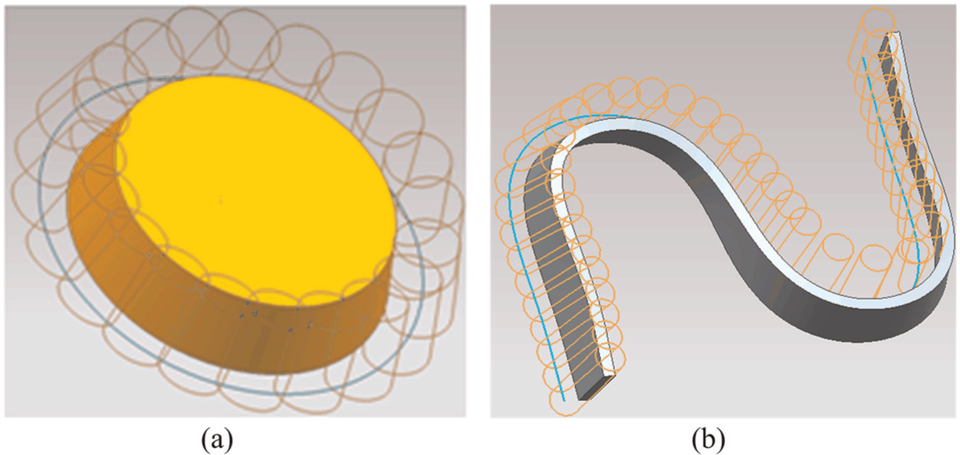
Tool paths for the two machining tests: (a) NAS 979 test piece and (b) S-shaped test piece.
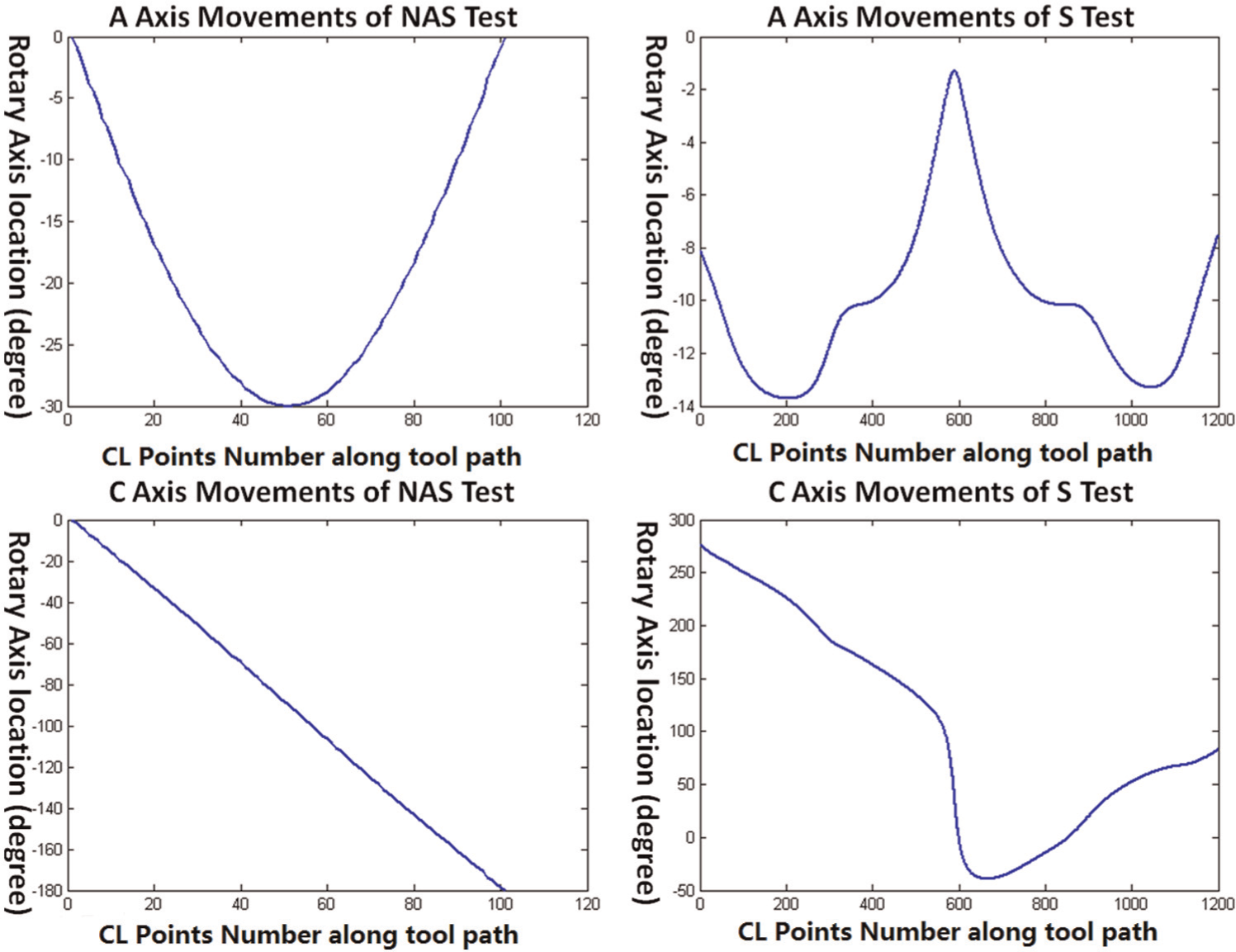
Comparison of the movements about rotary axes.
Comparison of profile measurement requirements
For the NAS 979 test, the profile measurement is simply carried out using Coordinate Measuring Machine (CMM). Only 16 points need to be measured along the upper circle line and the lower circle line to evaluate the accuracy of the machine tool. For the S-shaped test piece, obviously, the measurement is more complicated due to its more complex geometry. To measure the profile of a free-form surface using CMM, the method of taking a group of sampling points as the representation of a surface is commonly applied in industry. There are many different strategies for point sampling; 18 however, the uniform sampling in the u and v parameter direction strategy is mostly used due to its simplicity. Normally, 75 points are taken for the ruled surface measurement. Of course, the more points measured, the higher the measuring accuracy that can be achieved.
In order to avoid collision, an indexable probing system is required for the profile measurement because several measuring postures are needed. Probe approach direction must be normal to the surface. In most cases, the CMM with a normal probing system is known to have high accuracy, repeatability, and reliability, and the measuring uncertainty can be controlled within 4 μm of a CMM with a normal probing system which is good enough for the S-shaped test piece. As this test piece requires an indexable probing system, arguments regarding the measurement uncertainty are extensive during ISO meetings. Therefore, there is a need to do an experimental study to compare the measuring uncertainty with the normal one.
A CMM with Renishaw PH10M probing system as shown in Figure 3 is taken for the experimental study. Two strategies for measuring 28 points on the ruled surface are determined. In Strategy 1, 28 points are measured under the initial posture without any rotation of A and B axes. In Strategy 2, 28 points are measured under three different postures as shown in Figure 4. In Strategy 2, 12 points are measured under the posture shown in Figure 4(a), 8 points are measured under the posture shown in Figure 4(b), and the remaining 8 points are measured under the posture shown in Figure 4(c). To minimize the measuring uncertainty, the probing system under each posture should be calibrated using a standard calibration ball as shown in Figure 5. For both strategies, 15 times measurement is needed to evaluate the measuring repeatability.
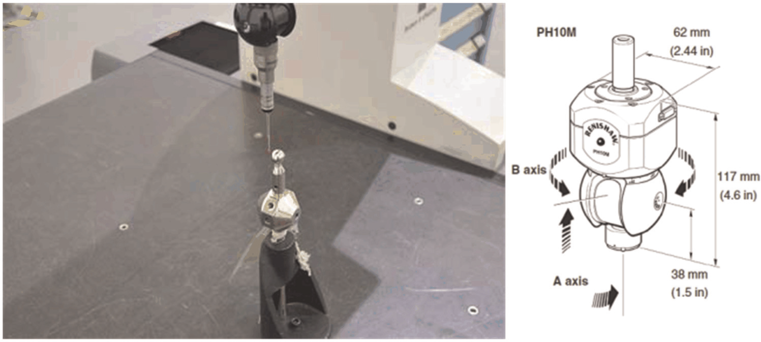
A CMM with Renishaw PH10M probing system.
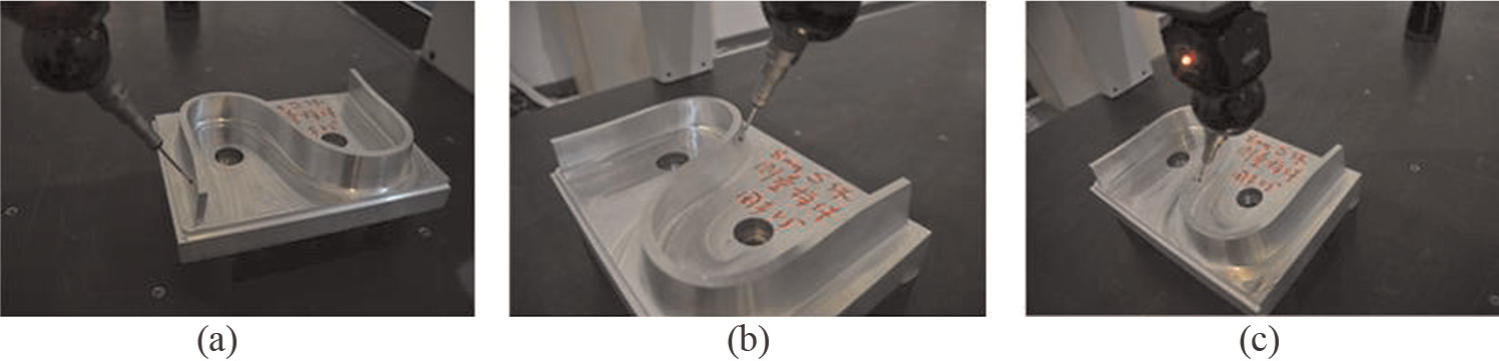
Three different measuring postures for strategy 2.
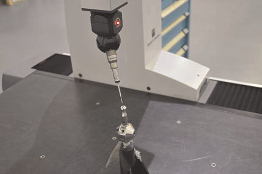
Probing system calibration.
The measured errors at 28 points of 15 times are shown in Figure 6. The maximum and minimum measured errors are always taken for evaluation if the test piece is within specified tolerance. Figure 7 shows the maximum and minimum measured errors of each time. Table 1 gives a comparison of measured results under the two different strategies.
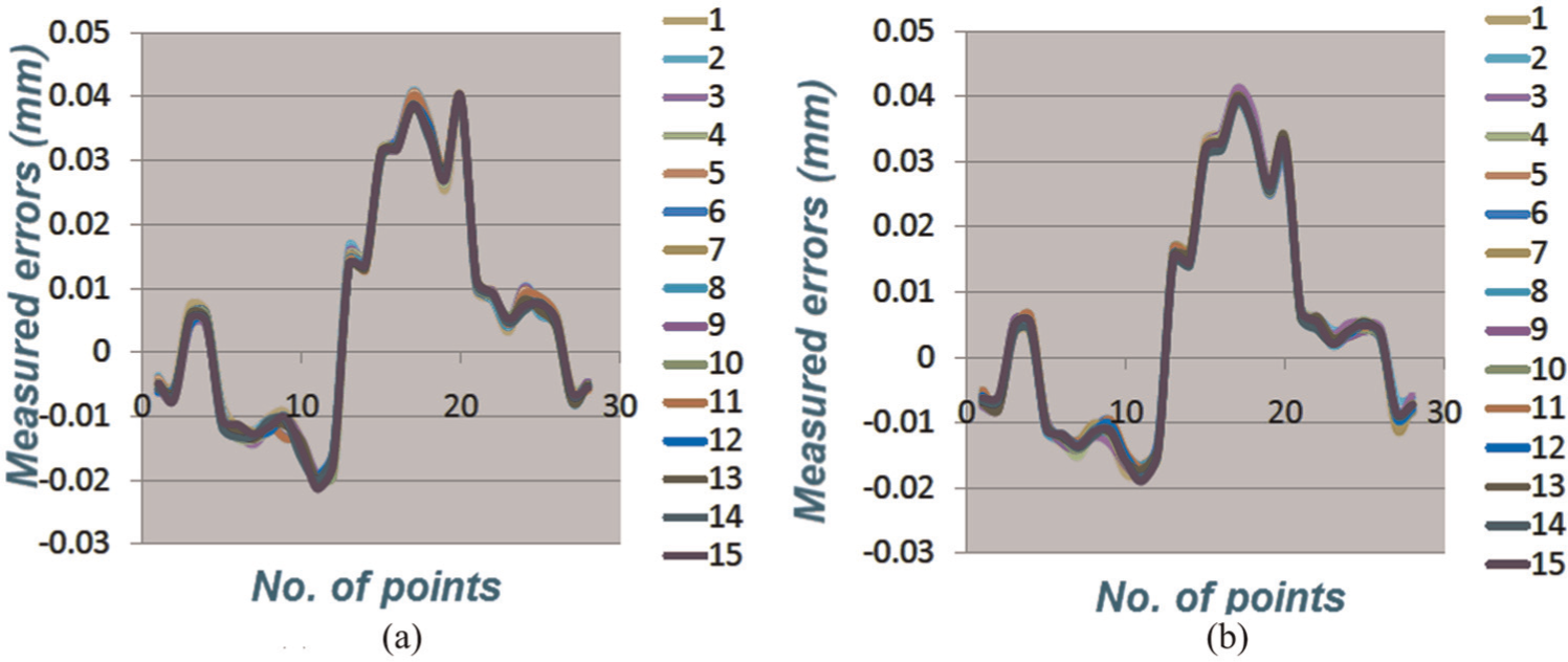
Measured errors at 28 points of 15 times: (a) strategy 1 and (b) strategy 2.
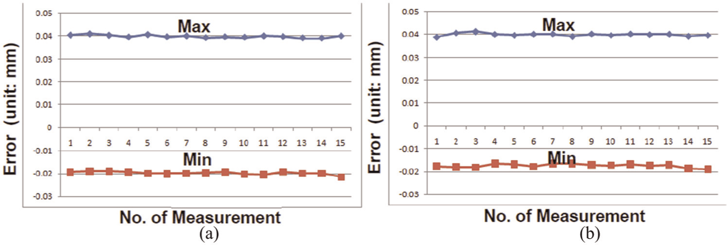
Maximum and minimum measured errors at each time: (a) strategy 1 and (b) strategy 2.
Comparison of measured results.
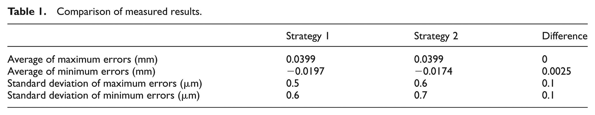
As can be seen from Table 1, the average of the maximum errors of the two different strategies is the same; the difference of the average minimum errors is only 2.5 μm. The difference of the standard deviation of the two strategies is only 0.1 μm which is small enough to be ignored which implies that the repeatability of both strategies is high enough. The measured results show that measuring with an indexable probing system would not increase measurement uncertainty much. It may only slightly affect the measuring results. As the tolerance zone of the S-shaped test piece is 100 μm, the influence of the indexable probing system could be ignored.
Latest development of the proposed standard
Changes have been made by the authors’ working group during the development of the proposed standard according to the comments from international experts. The updated version of the S-shaped test piece delivered by China is in the document. 19 Comparing to the original version, the main changes are in three aspects which are introduced as follows.
Geometric definition of the test piece
In the original version of the S-shaped test piece, each curve for ruled surface definition is generated by interpolation of 50 points. Since many experts concerned that the interpolation algorithm may affect the result of curve generation, in the latest version of the working draft, each curve is defined by a control polygon with 12 points. The definition of the first ruled surface is shown in Figure 8(a) and the position of all control points is given in the table in Figure 8. The definition of the second ruled surface is shown in Figure 8(b), and the final shape of the test piece is shown in Figure 8(c). The new definition adopts the B-Spline definition method which is introduced by ISO 10303 and has been widely applied by computer-aided design/computer-aided manufacturing (CAD/CAM) software. This change guarantees the uniqueness of the geometric definition, and much fewer points significantly reduce the definition complexity.
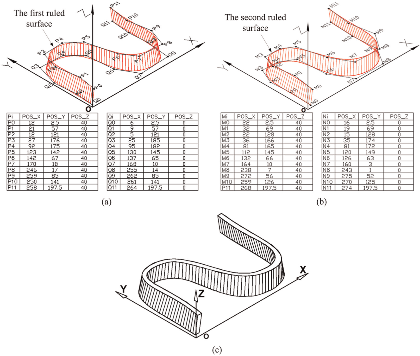
Geometric definition of the test piece: (a) the first ruled surface and its control points, (b) the second ruled surface and its control points, and (c) the final ruled surface.
Raw material requirement
In the original version, the raw material is given as a block; thus, a lot of materials need to be removed before finishing. As this machining test only concerns the finishing result, raw material is re-defined as shown in Figure 9 according to the condition that it has been prepared for finishing. This change avoids the influence of roughing process and can guarantee the finishing result truly reflecting the machining accuracy of the machine tool.
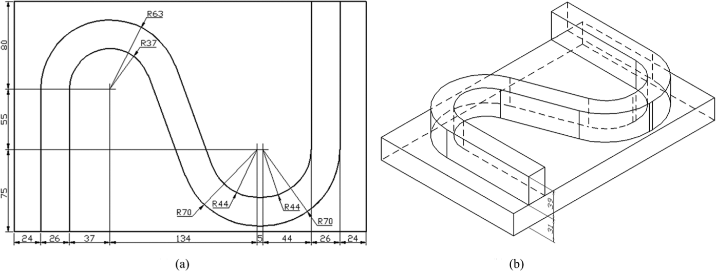
Geometric definition of the raw material: (a) top view and (b) isometric view.
The datum plane for measurement
In the original version, the measurement coordinates are defined by two holes and the bottom plane of the test piece. It is changed to creating the measurement coordinates according to three machined planes which remove the drilling process and its influence on the measurement uncertainty. Three datum planes (XY, YZ, and XZ planes) are shown in Figure 10. After finishing of the S-shape, these three datum planes should be machined and will be taken as the reference planes for re-constructing the measuring coordinate system to guarantee that the measuring coordinate system is the same as the machining coordinate system.
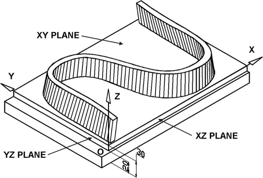
Three datum planes for measurement.
These changes significantly improve the feasibility of the application of the S-shaped test piece as a test standard for acceptance of five-axis machine tools for production use. More work will be done according to the discussion results among ISO/TC39/SC2 experts.
Conclusion
This article introduces a new standard using an S-shaped test piece for testing the performance of five-axis machine tools. The characteristics and superiority of the test piece are analyzed by comparing with the NAS test, and it is concluded that the S-shaped test piece can better fit the requirement of testing the performance of five-axis machine tools. The profile measurement method of the S-shaped test piece with CMM is analyzed through an experiment study, and the results demonstrated that the indexable probing system only slightly increases the measurement uncertainty which could be ignored. Latest development status of this S-shaped test piece according to ISO experts’ comments is introduced. Modification has been made to simplify the definition, reduce the testing workload, and improve the measurement accuracy of the proposed testing method.
Even though the proposed method shows a lot of advantages, it also has some drawbacks such as heavier testing workload and more complex measurement than using frustum cone test. Due to such drawbacks, it needs some further research work to improve its applicability as an international standard.
Footnotes
Declaration of conflicting interests
The authors declare that there is no conflict of interest.
Funding
This research received no specific grant from any funding agency in the public, commercial, or not-for-profit sectors.