
Abstract
Distribution of loads and contact stress has a great influence on fatigue life of bearings. In view of the fact that the nonload area is ubiquitous in cylindrical roller bearings, there is a method for prolonging the fatigue life design by adjusting the working clearance of cylindrical roller bearings. In this article, optimization model of fatigue life of cylindrical roller bearings is developed with a quasi-dynamic method and calculated method of bearing life based on micro-area contact, considering the effect of assembly interference, temperature rise, and high-speed centrifugation. Aiming to the different geometry parameters and operating parameters of bearings, the effects of assembly interference on bearing fatigue life are discussed. The results show that the optimum fatigue life of roller bearings is achieved at negative working clearance with the loads distributed evenly within half ring. The optimum working clearance of roller bearings is not influenced by radial load. But with the increase in pitch diameter or decrease in rolling elements, the optimum assembly interference increases, and accelerating revolution of roller bearings will increase the optimum assembly interference as well.
Introduction
Initial clearance, one of the important design parameters of rolling bearings, influences the load-carrying properties and fatigue life of bearings directly. 1 In the past several decades, a number of researches on roller modification have been reported,2–4 and modification model of cylindrical roller was proposed, such as changing the fitness between roller and raceway, using different modification curves, and so on,5,6 to make full use of roller length and improve edge stress concentration of rollers effectively. However, since cylindrical roller bearings only bear radial load, its initial clearance could not be eliminated through preloading such as ball bearings. There is still a nonloading region on cylindrical roller bearings in operation. Moreover, external factors caused by service environment and working conditions of bearings (e.g. bearing assembly, temperature rise, and centrifugal force) will make actual working clearance disagree with the initial clearance. As a result, working clearance of bearings is necessary to analyze dynamic properties and predict fatigue life of bearings accurately.
Additionally, load distribution in loading region of the cylindrical roller bearings will directly cause different fatigue life of rollers at different azimuth angles. The ISO standard algorithm which calculates fatigue life of bearings based on rated dynamic load and equivalent dynamic load could not predict the fatigue life of bearings accurately. Under this circumstance, the overall fatigue life of bearings can only be determined by fatigue life of different rollers and the rings. 7 To ensure prediction accuracy of fatigue life, internal load of bearings is often calculated by quasi-dynamic analysis because complete dynamic analysis will complicate the calculation significantly, 8 and quasi-static method based on the hypothesis of ring control theory is inapplicable to high-speed bearings for its poor calculation accuracy. 9 Compared to other methods, quasi-dynamic analysis can provide satisfying calculation accuracy and efficiency. Therefore, quasi-dynamic method is used most widely in practical engineering. 10
To analyze the effect of working clearance of cylindrical roller bearings on internal load-carrying properties and fatigue life and prolong fatigue life of cylindrical roller bearings by optimizing the assembly interference, this article established a mathematical model based on theoretical modeling and simulation analysis to calculate the working clearance and predict fatigue life of bearings. Through performance analysis and optimization design of assembly interference, the influence law of assembly interference of cylindrical roller bearings on the fatigue life is discussed under different structural parameters and working conditions.
Working clearance analysis and fatigue life calculation of cylindrical roller bearings
Analysis of working clearance
Calculation of working clearance of bearings involves the effects of bearing assembly, temperature rise, and centrifugal force on bearing initial clearance

where
Clearance variation caused by assembly interference
As Figure 1 shows, bearing installed through interference fit suffers deformations in both inner raceway and outer raceway, which will influence its initial clearance. Therefore,

Sketch of interference at bearing installation: 1 (a) interference between inner ring and shaft and (b) interference between outer ring and bearing housing.
Clearance variation caused by temperature rise
Temperature rise causes thermal expansion of bearing elements, thus influencing the bearing clearance. Under free state,

The diameter expansion of bearing elements is calculated according to the coefficient of thermal expansion of corresponding material and temperature rise. 11
In addition, diameter expansion of bearing elements caused by temperature rise will also affect the fitting surface, further changing the bearing clearance. Interference of fitting surfaces caused by thermal expansion is

Based on the deformation compatibility condition in

Therefore,

Clearance variation caused by centrifugal force
Under free state,

Diameter changes of elements caused by the rotating speed (

where
Similarly, diameter changes of elements caused by high-speed centrifugal force will influence the fitting surfaces and thereby change the bearing clearance. Interference of fitting surfaces caused by centrifugal force is

Based on the deformation compatibility condition in

Therefore,

Calculation model of internal contact load
External loads and coordinates of cylindrical roller bearings are shown in Figure 2.

Sketch of cylindrical roller bearings and external loads.
The positional relation between roller and raceways is shown in Figure 3.
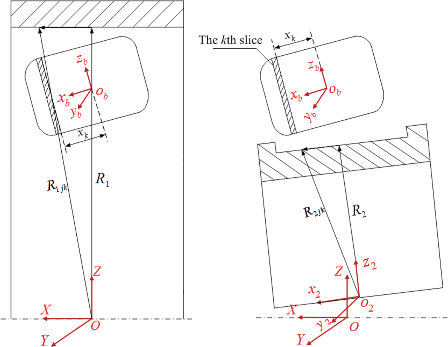
Relative positions of roller slices to inner and outer raceways: (a) roller slice and outer ring and (b) roller slice and inner ring.
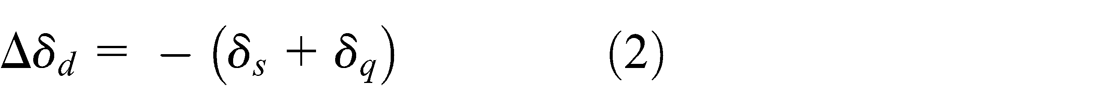
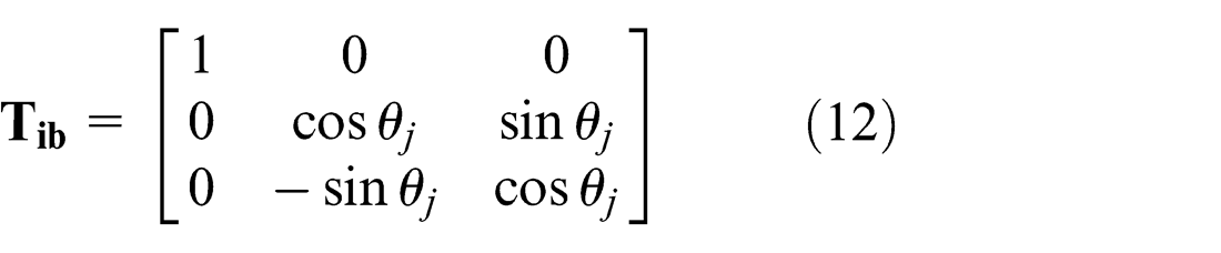
Slice method is used on the roller along its axis. According to the azimuth angle of the roller in fixed coordinate and position of roller slice in the roller position coordinate
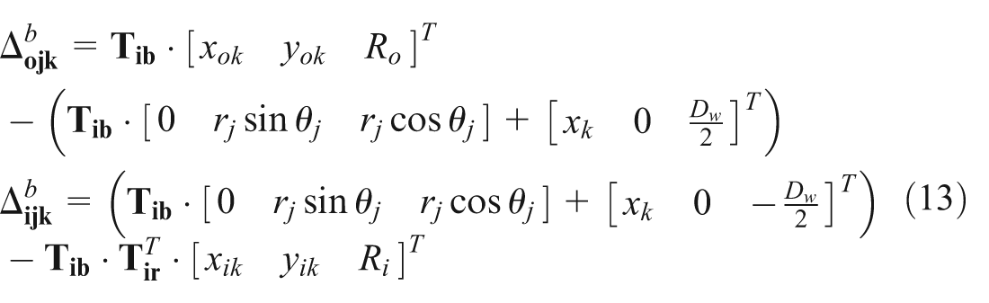
where Ro
, Ri
, and rj
are distances from the center of outer raceway, inner raceway, and jth roller to the bearing center, respectively; xok
, yok
, xik
, and yik
are the coordinates of kth slice on the raceway, which are calculated by letting the first and second components of
According to displacement–deformation compatibility condition between each roller slice and raceway, displacements of geometry centers between roller slice and raceways will correspond coordinately to deformation of roller slice and raceways at contact points. Deformation of roller slice and raceways is calculated by the following formulation

where

where μ is the viscosity of oil, λ is the pressure–viscosity coefficient; Uj is sliding velocity between ring and jth roller; R′ and E′ are equivalent radius and elastic modulus of roller and ring, respectively; Qjk is the contact load between slice k of roller j and raceway; and w is the slice width, w = l/m, l and m are roller length and slice number, respectively.
According to the deformation of roller slice, contact pressure between roller slice and raceways is calculated through Palmgren theory. 1 Contact loads on slice k of roller j are calculated by the following formulation 1

Moreover, the sum of contact force on all the roller slices should balance coordinately with external loads

Besides the balance and coordination between roller slice and raceways, coordinative balance should be kept between rollers and cage, as well as rings and cage. The specific load calculation method refers to Cui et al. 13 Combining load balance equations in bearings, the Newton–Raphson method and steepest descent method are employed to calculate the load and the axial load distribution on each roller.
Calculation model of fatigue life
Based on the slice method, the raceway (length l) was cut into m slices, as shown in Figure 4. Each slice can be viewed as a l/m wide raceway. Then, the basic rated dynamic load of each slice could be calculated as follows,
14
where

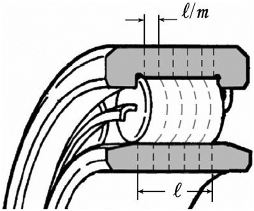
Roller and raceway are divided into m slices along the axis of the roller using the slice method. 11
Then, the fatigue life of raceway slice is 14


Considering that the unit of roller fatigue life calculated by equation (20) is the roller revolution number, it is necessary to convert roller revolution number into revolution number of the inner ring. Also, the roller revolution numbers i while the inner ring ran by one circle is

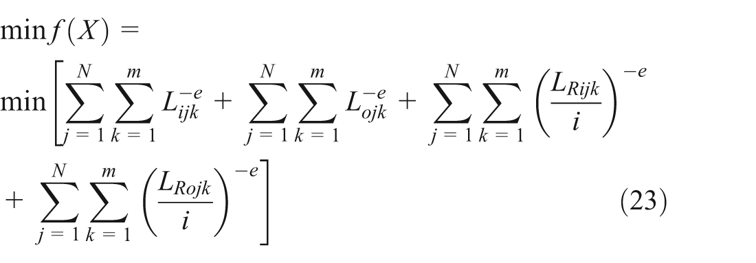
Dividing the calculated roller fatigue life by i is the revolution number of inner ring upon roller fatigue. Therefore, the overall fatigue life of roller bearings can be expressed as 14

Optimization model of assembly interference
Optimization is to prolong the fatigue life of bearings under specific working condition to the maximum extent. The objective function is
Interferences of shaft and inner ring during roller bearing assembly are viewed as design variables

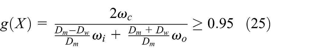
Since excessive differential sliding between the rolling elements and ring of high-speed rolling bearing will generate abundant friction heats which are easy to cause burning and scuffing failures of the assistant contact surface, it is necessary to control sliding of rolling elements at bearing operation. The sliding of rolling elements can be characterized by sliding rate of cage. Generally, sliding rate of cage is controlled less than 5%. The corresponding constraint is
Independent variables in the objective function (
Optimization calculation and discussion of assembly interference
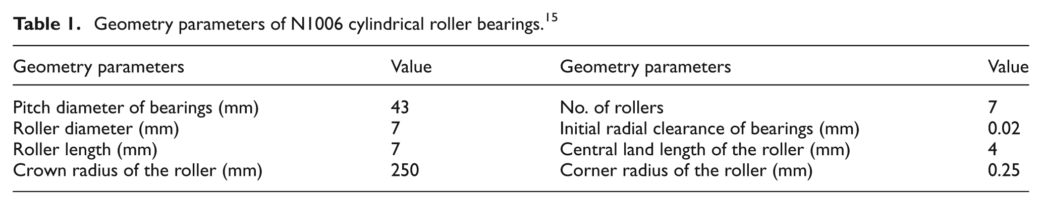
In this article, the optimization analysis of assembly interference was based on N1006 cylindrical roller bearings as an example. Related geometry parameters, material parameters, assembly parameters, and working conditions are listed in Tables 1–3.
Geometry parameters of N1006 cylindrical roller bearings. 15
Material parameters of cylindrical roller bearings. 15

Operating parameters and installation parameters of cylindrical roller bearings.

MIL-L-7808 lubrication oil was used in the testing bearings. Density and dynamic viscosity of lubrication oil are 960 kg/m3 and 0.277 Pa s, respectively. The traction coefficient

where u is relative sliding speed of the contact surface. A, B, C, and D are undetermined coefficients of lubricant, which are determined through the following relationship according to the traction characteristics of lubricant

Effect of working clearance on dynamic properties of cylindrical roller bearings
The working clearances of the roller bearings under normal working condition and extreme working condition were calculated as 0 and −7 μm, respectively. The negative clearance reflects that the rolling elements have suffered certain pre-deformation when neglecting external load. Performances under these two working clearances were compared to that under initial clearance to analyze the effect of working clearance on bearing performance. The average sliding ratio and rotating speed of rolling elements under three radial internal clearances are presented in Figure 5. With the increase in radial internal clearance, internal loading region of bearing will be narrowed, thus weakening the traction effect of raceway on rolling elements. As a result, average sliding ratio and rotating speed of the cage fluctuate within wider ranges.
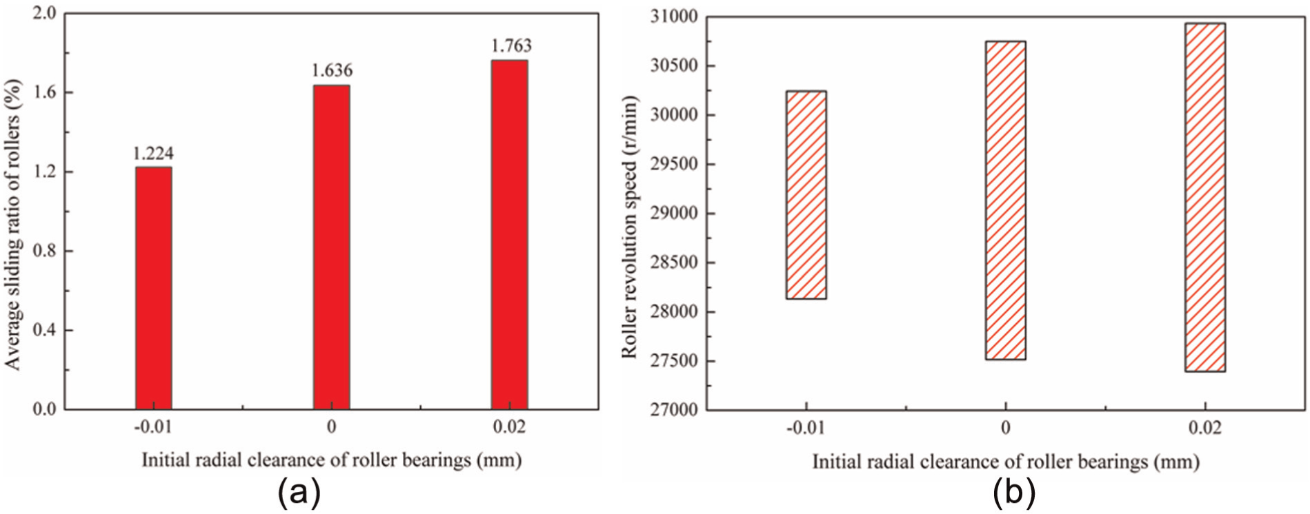
Effect of initial clearance on roller (a) average sliding ratio and (b) revolution speed.
Figure 6 is the spectrogram of interaction between cage and rolling elements under different radial internal clearances. Figure 7 is the spectrogram of interaction between cage and guide ring under different radial internal clearances. With the decrease in radial internal clearance, the rotating speed fluctuation of rolling elements weakens, thus reducing dominant frequencies of the collision between cage pockets and rolling elements. The dominant frequency of force between the cage and guiding ring, which used to balance the impact force of the rolling elements, decreases accordingly.
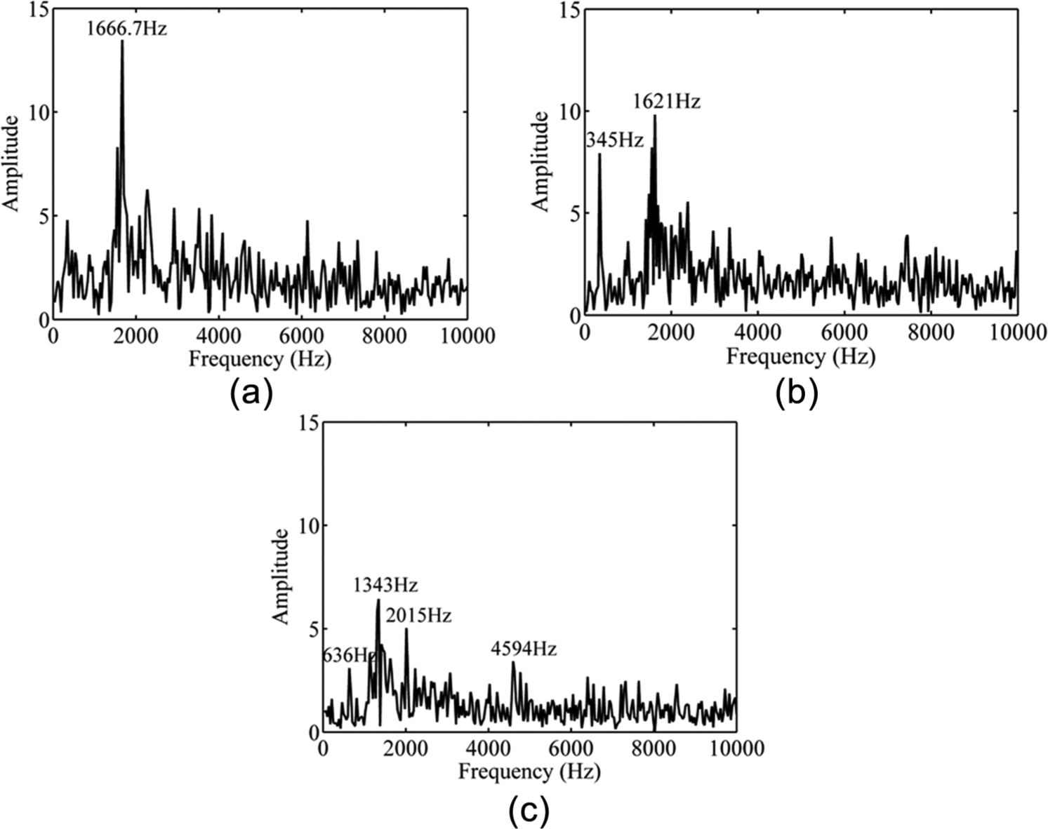
Spectrum of the interaction between cage pocket and roller on different bearing initial clearances: (a) 20, (b) 0, and (c) −7 μm.

Spectrum of the interaction between cage and guiding ring on different bearing initial clearances: (a) 20, (b) 0, and (c) −7 μm.
According to the calculation method of fatigue life mentioned above, the fatigue life under normal working condition (bearing clearance is 0 μm) and extreme working condition (bearing clearance is −7 μm) is 15,428 and 505 h, respectively, indicating that extreme load shortens the fatigue life significantly. Comparatively, if the effect of working condition on bearing clearance is not considered, the fatigue life under normal working condition and extreme working condition based on the initial clearance is 7234 and 131 h, respectively. This confirms the significance of bearing clearance in calculating fatigue life because bearing clearance can affect contact load between the rolling elements and ring as well as load distribution directly.
Optimization analysis of assembly interference
Considering the effect of working clearance on fatigue life, optimum design of bearing working clearance was proposed under fixed working condition. Based on the relationship between assembly interference and working clearance, the optimum assembly interference was calculated. Although the fatigue life of bearing under extreme working condition is far shorter than that under normal working condition, the optimum design was still calculated under normal working condition, because extreme working condition accounts for a very small proportion in the whole working cycle.
The effect of working clearance on bearing load, fatigue life, and number of rolling elements is shown in Figure 8. Smaller working clearance can contribute more even internal load distribution and increase rolling elements in the loading region. However, pre-deformation caused by negative clearance will also produce additional load on rolling elements in the loading region. Therefore, the working clearance under full loading of all rolling elements is not the optimum working clearance. Under normal working condition, the longest fatigue life is achieved at −11 μm working clearance. The corresponding relationship between assembly interference and working clearance is shown in Figure 9. Figure 9 reveals that the optimum fitting interference between shaft and the inner ring shall be designed 26 μm to achieve the best performance of the roller bearing.

Effect of working clearance on loading performance and fatigue life of bearings: (a) fatigue life and maximum contact load of bearings and (b) total number of rollers in the loading zone.

Assembly interference between shaft and bearing inner ring corresponding to the working clearance.
Effect of geometry parameters on the optimum assembly interference
Effect of pitch diameter on the optimum assembly interference
The effect of assembly interference and pitch diameter on fatigue life and working clearance is shown in Figure 10. With the increase in pitch diameter, the optimum assembly interference increases gradually (from 21 to 32 μm), but the corresponding working clearance reduces (from −8.5 to −13 μm). This is mainly because the revolution radius of rolling elements increases with the increase in pitch diameter, forcing rolling elements approaching to the outer ring raceway by the centrifugal force during bearing running. Thus, to maintain uniform load distribution within the loading region of bearings and prolong its fatigue life, greater assembly interference (or smaller working clearance) is needed to adjust pre-deformation of rolling elements.
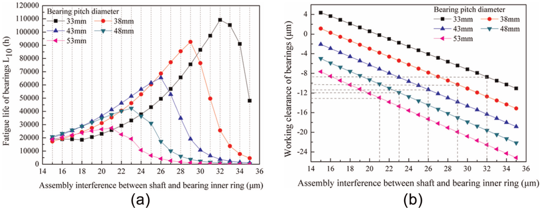
Effect of assembly interference and pitch diameter on fatigue life and working clearance of roller bearings: (a) fatigue life of bearings and (b) working condition of bearings.
Furthermore, Figure 10(a) shows an inversely proportional relationship between the optimum fatigue life of bearing (L
10) and pitch diameter (L
10 ranges from 109,200 to 27,440 h with the increase in pitch diameter). To depict the influence law of pitch diameter on the optimum fatigue life of bearing, the number of rolling elements in the loading region and load on the rolling element with maximum load under the optimum assembly interference were calculated (Table 4). Table 4 reveals that although different pitch diameters have different optimum assembly interferences, the number of rolling elements in the loading region under the optimum assembly interference is the same and load on the rolling element with maximum load is similar to each other. Since radial load on the bearing is fixed, rest rolling elements in symmetric distribution show basically same loads. According to the fatigue life calculation formula of roller bearing,
Number of rollers and maximum load in the loading area while the assembly interference is optimal.

Effect of number of rolling elements on the optimum assembly interference
The effect of assembly interference and number of rolling elements on fatigue life and working clearance is shown in Figure 11. The number of rolling elements is inversely proportional to the optimum assembly interference (optimum assembly interference ranges from 27 to 24 μm with the increase in the number of rolling elements) but proportional to fatigue life of bearings (L 10) and working clearance (with the increase in the number of rolling elements, L 10 ranges from 30,480 to 83,370 h and working clearance ranges from −12 to −10 μm). With the increase in the number of rolling elements, load distribution within the loading region of bearing will be changed. On one hand, there are more rolling elements to bear loads. On the other hand, the rolling element with maximum load will bear fewer loads, which will reduce deformations between rolling elements and raceway. Consequently, the fatigue life of bearing prolongs, while working clearance increases gradually.
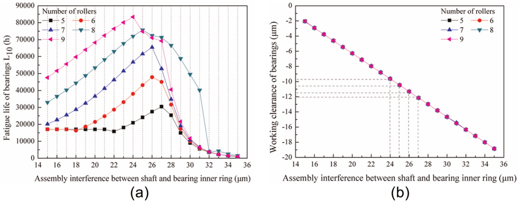
Effect of assembly interference and roller number on fatigue life and working clearance of roller bearings: (a) fatigue life of bearings and (b) working condition of bearings.
Effect of working conditions on the optimum assembly interference
Effect of radial load on the optimum assembly interference
The effect of assembly interference and radial load on fatigue life and working clearance is shown in Figure 12. It can be seen from Figure 12(a) that the optimum assembly interference is same (26 μm) under different radial loads. Thus, it can be concluded that the radial load does not influence the optimum assembly interference. In other words, the optimum working clearance of bearing is immune to the radial load. However, fatigue life of bearing (L 10) drops quickly (from 109,400 to 635 h) as the radial load increases. Based on the optimization analysis of assembly interference (section “Optimization analysis of assembly interference”), load shall be distributed within half ring of the bearing upon the optimum fatigue life. This requires constant optimum working clearance under fixed pitch diameter and rolling elements. However, radial load growth will increase load on rolling elements within the loading region directly, thus shortening the optimum fatigue life significantly.

Effect of assembly interference and radial load on fatigue life and working clearance of roller bearings: (a) fatigue life of bearings and (b) working condition of bearings.
Effect of rotation speed on the optimum assembly interference
The effect of assembly interference and rotating speed on fatigue life and working clearance is shown in Figure 13. Rotation speed is proportional to the optimum assembly interference (optimum assembly interference ranges from 18 to 26 μm with the increase in rotation speed) but inversely proportional to the fatigue life of bearing (L 10) and working clearance (with the increase in rotation speed, L 10 ranges from 31,880 to 65,460 h and working clearance ranges from −6 to −11 μm). Higher rotation speed will accelerate the revolution of rolling elements which will approach to outer raceway by the increasing centrifugal force. Under this circumstance, the rolling elements have to produce greater pre-deformation at initial state in order to maintain load distribution within half bearing ring. In other words, the optimum working clearance shall be reduced, while assembly interference to adjust working clearance shall be increased. Meanwhile, the increasing centrifugal force of rolling elements will increase contact load and contact stress between the rolling elements and outer raceway. These will shorten the fatigue life of both outer raceway and rolling elements, finally shortening the overall fatigue life of bearings.

Effect of assembly interference and rotation speed on fatigue life and working clearance of roller bearings: (a) fatigue life of bearings and (b) working condition of bearings.
Conclusion
To optimize the fatigue life of roller bearing, a calculation method of assembly interference was proposed in this article based on the analysis of working clearance and fatigue life. The effect of working clearance on dynamic properties of cylindrical roller bearings and the optimum assembly interference was analyzed through a case study. Moreover, the influence law of geometry parameters and working conditions of cylindrical roller bearings on the optimum assembly interference was discussed. It concludes that
Working clearance growth of roller bearing will increase sliding ratio and rotating speed fluctuation of the cage;
The optimum fatigue life of roller bearing is achieved at negative clearance when working loads distribute evenly within half ring;
With the increase in pitch diameter or decrease in rolling elements, the optimum assembly interference increases, while the corresponding working clearance and optimum fatigue life (L 10) decrease gradually;
The optimum working clearance of roller bearing is immune to radial load. However, radial load growth will shorten the optimum fatigue life (L 10) quickly. In addition, accelerating revolution of roller bearing will increase the optimum assembly interference but decrease the corresponding working clearance and optimum fatigue life (L 10) gradually.
Footnotes
Appendix 1
Academic Editor: Jeng-Haur Horng
Declaration of conflicting interests
The authors declare that there is no conflict of interest.
Funding
This work has received support from the National Basic Research Program of China (2013CB632305), Science and Technology Foundation of GuiZhou Province of China (Qian Ke He J Zi [2014]2172), and Natural Science Research Project of Education Department of GuiZhou Province of China (Qian Jiao He KY Zi [2014]294).