
Abstract
In this article, two types of actuators are applied for a lower limb exoskeleton. They are DC motors with the harmonic drive and the pneumatic artificial muscles. This combination takes advantages of both the harmonic drive and the pneumatic artificial muscle. It provides both high accuracy position control and high ratio of strength and weight. The shortcomings of the two actuators are overcome by the hybrid actuation, for example, low control accuracy and modeling difficult of pneumatic artificial muscle, compactness, and structural flexibility of DC motors. The design and modeling processes are discussed to show the proposed exoskeleton can increase the strength of human lower limbs. Experiments and analysis of the exoskeleton are given to evaluate the effectiveness of the design and modeling.
Introduction
About 7%−10% of the world’s population have different kinds of disabilities. The population census of Mexico stated that in the year 2010, 5.1% of the total population of the country had difficulty in walking or moving (49% men and 51% women). Some people had more than one disability, for example, motor and language problems with cerebral palsy. A total of 39% of the disabled people suffer due to diseases, 23% due to old age, 16% due to inheritance during pregnancy or at birth, 16% due to accidents, and 8% due to other reasons. 1 For these causes, rehabilitation and increasing strength are possible methods to recover completely or partially.
The exoskeletons are a class of devices which are designed as pants or jackets, worn by the human operator. These wearable robots are metachromatic devices to increase human strength and resistance. They serve as tools to enhance or replace partial musculoskeletal systems. They can be applied to recover the injuries, such as neurological and neuromuscular diseases, hemopoietic or muscular dystrophy, and muscle degeneration. So they are useful to assist human limb rehabilitation.
The lower limb exoskeletons are the most common wearable robots because human lower limbs are more susceptible to injuries due to the accidents, neuromuscular and neurological diseases, and muscular degeneration. One of the most important lower limb exoskeletons is Berkeley Lower Extremity Exoskeleton (BLEEX). 2 It is designed to enhance the strength of the lower limb to help carry heavy loads. The actuators power the full legs, hip, knee, and ankle joints. The Defense Advanced Research Projects Agency (DARPA) project supports some successful exoskeletons, such as Sarcos Exoskeleton 3 and the MIT Exoskeleton. 4 The lower limb exoskeletons for nonmilitary applications usually enhance the human capability, for example, hybrid assistive limb (HAL) robots 5 power the hip and knee joints directly with a DC motor and the harmonic drive gear.
The traditional lower limb therapies often focus on workouts or passive gaits to improve active training systems. Passive training systems are static robotic systems which guide limb movements. The systems move the joints to achieve an optimal effect from the therapeutic and functional points of view. The goals of these systems are to obtain effective strengthening of muscles. The active training systems (see Figure 1) are based on exoskeleton robots, for example, LokoHelp, 6 ALEX, 7 LOPES, 8 and AutoAmbulator. 9 The treadmill training can control step speed easily. A compliant robotic orthosis for treadmill training is proposed by Hussain et al. 10 The challenges of the active training systems are the movement coordination between the motors and patients (see the prototypes of Lambda 11 and Tsukuba 12 ). In this article, we use the electromyography (EMG) sensors to monitor the muscular activity to actuate the joints.

Exoskeleton for multiple purposes: (a) augmentation of force and (b) active gait rehabilitation.
The actuation of the exoskeleton robots can be classified into two types: motor actuation and pneumatic artificial muscle (PAM). Most of the robot manipulators use motors to move their joints. The exoskeleton robot working space is the same as the human existing space. This requires high levels of safety and actuation, and it is not common in general industrial robots. In the 1950s, J.L. McKibben invented PAM to motorize pneumatic arm orthotics for helping control handicapped hands. PAM is simple in design and is made of a rubber inner tube covered with a shell braided according to helical weaving. When the inner tube is pressurized by air, the muscle inflated and contracted. Usually, it uses open-loop control because it is easy to use the pressure variation for those with disabilities. The advantages of PAM are as follows: it is similar to human skeletal muscles in size, and it has high power/weight and power/volume ratios compared with motor actuation. In Costa and Caldwell, 13 a 10-degree-of-freedom (DoF) lower limb exoskeleton is developed. It is driven by pneumatic muscles to achieve force augmentation and active walking training. The main drawback of PAM is that the control accuracy is very low.
The objective of this article is to design a high control accuracy, high torque, and light robot exoskeleton. The high torque DC motor is heavy. The high torque PAM actuator is light and has low control accuracy. We take the advantages of both the DC motor and the PAM. This combination provides high accuracy of position control and high power/weight ratio. The mechanical and electronic characteristics of human limbs are analyzed for the actuation of the lower limb exoskeleton. The main disadvantage of the combination of two different types of actuators is that the control scheme is more complex. A special design process for the hybrid control is discussed considering the mechanical construction and electronic implementation.
The main difference with the other lower limb exoskeletons is that we use the hybrid actuation, which takes advantages of both the harmonic drive and the PAM. It can be used for force amplification and lower limb rehabilitation. It is an efficient tool for old people and patients with muscular dystrophy. Experiments and analysis of the exoskeleton are carried out to evaluate the effectiveness of the design and modeling.
Lower limb exoskeleton design
Anthropometry and lower limb model
The anthropometry factors of human body are the base of the exoskeleton design. We first collect data from different individuals, groups, races, and so on. Then, we study the anthropometry of the lower limbs of the target population. The lower limb exoskeleton design is based on the Mexican population reported by Prado León.
14
This study includes the size of the male and female population aged between
Mexican workers aged between 18 and 65 years.

This study is realized with a total of

Standard properties of the male and female bodies.
Comfort angles of lower limb joints.
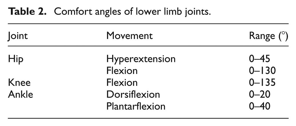
The motion ranges of human joints are another important anthropometry factor. By analyzing many samples, we found that the maximum ranges of the joints are not so important for the robot design. However, the comfort angles of the joints decide whether the robot causes pain or even danger to the patients. The comfort angles are given in Table 2. The clevis fitting comfort angles depend on the age, physical training, the anatomical and functional differences, and so on. These comfort angles are used to design the range of the exoskeleton joints.
Design of the lower limb exoskeleton
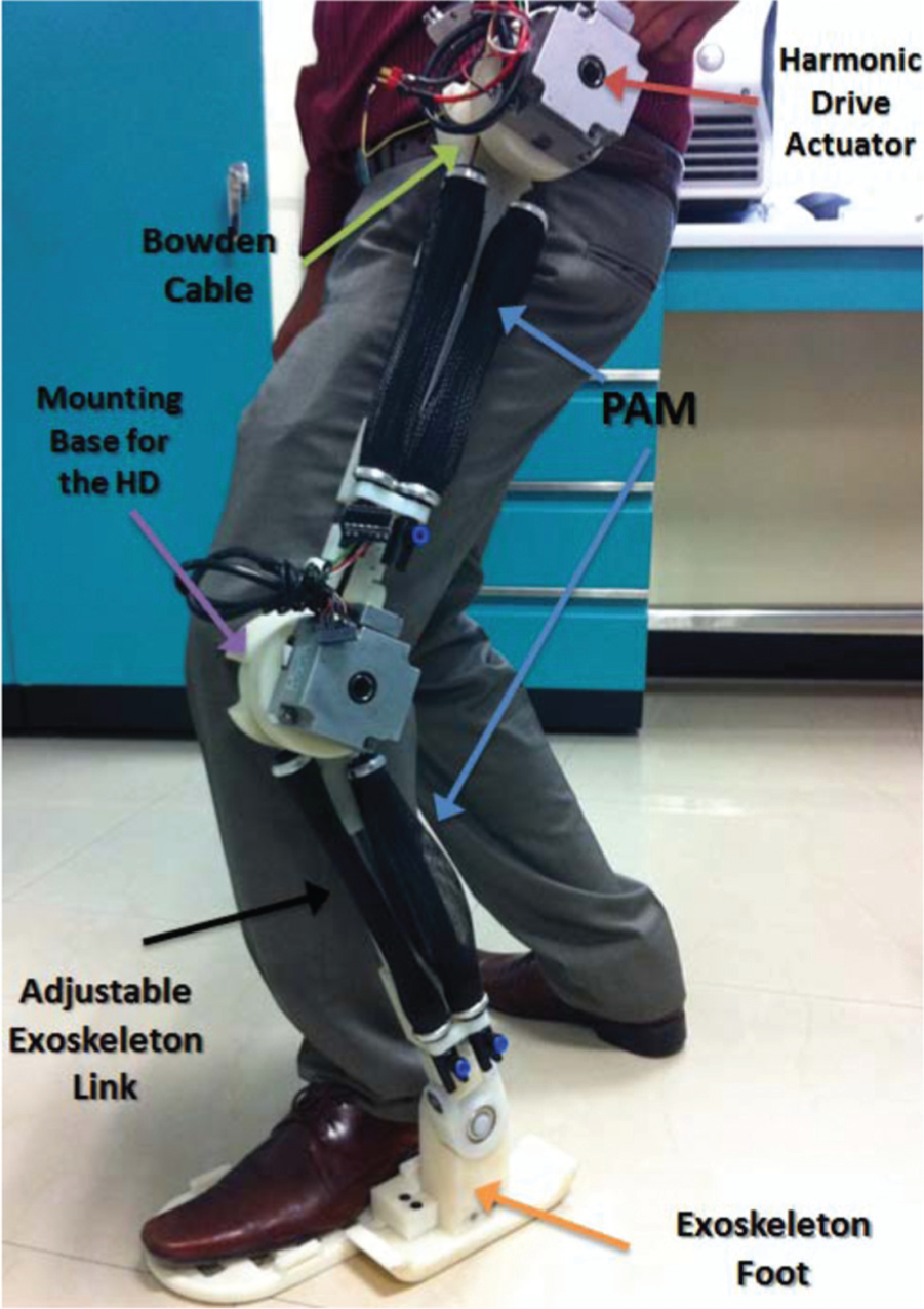
The fundamental principle of the joint design is to align the rotational axis of the exoskeleton with the anatomical rotational axes. In this article, we use pseudo-anthropomorphic architecture for 4-DoF lower limb robot. The hip and knee of the exoskeleton are active flexion/extension joints. In order to increase lower limb strength, a hybrid pneumatic-electric system with a harmonic drive actuator is applied directly on the joints. Each link uses two pneumatic muscles. The coupled transmission of these two PAMs is realized by the Bowden cables.
The lower limb exoskeleton robot is shown in Figure 3. Here, the joint of ankle flexion/extension is passive. The hip joint has 3 DoFs: abduction/adduction, internal/external rotation, and flexion/extension. The abduction/adduction and the internal/external rotation are passive, while the flexion/extension joint is active. The knee has 2 DoFs: flexion and abduction/adduction. Here, the flexion is active, while the abduction/adduction is passive. The PAM actuation is applied to two links: the link between the hip joint and the knee joint and the link between the knee joint and the ankle joint. The two active joints on the leg are shown in Figure 4.

Elements of the lower limb exoskeleton robot.
Lower limb exoskeleton is wearable.
The exoskeleton links are made of aluminum bars and tubes. We use computer numerical control (CNC) machine to construct the joint sections. The adjustable links are also made of aluminum tubes. To reduce the collision effect in the operator limbs, the adjustable elements for the upper and lower parts of the leg incorporate spring shock absorbers (see Figure 4).
Most of the existing lower limb exoskeletons do not allow to change activities. This reduces their capabilities. In this article, the waist link is connected to a flexible structure, such that the exoskeleton can change from one activity to another without making major modification. For example, the exoskeleton can perform as a gait trainer or as a treadmill. The exoskeleton length can be easily adapted to fit with the Mexican population considering their anthropometry factors.
The safety factors include mechanical, electrical, and software designs. The mechanical design uses physical stops to prevent segments in the joints. The electrical part has an emergency shut-off button to terminate motor motion. The easiest method is to use software to monitor power transmission integrity to limit motor currents, that is, motor torques. When the motor moves near to the limits, a brake command is sent. The software decides the maximum and minimum ranges of each joint.
Human–machine interfaces
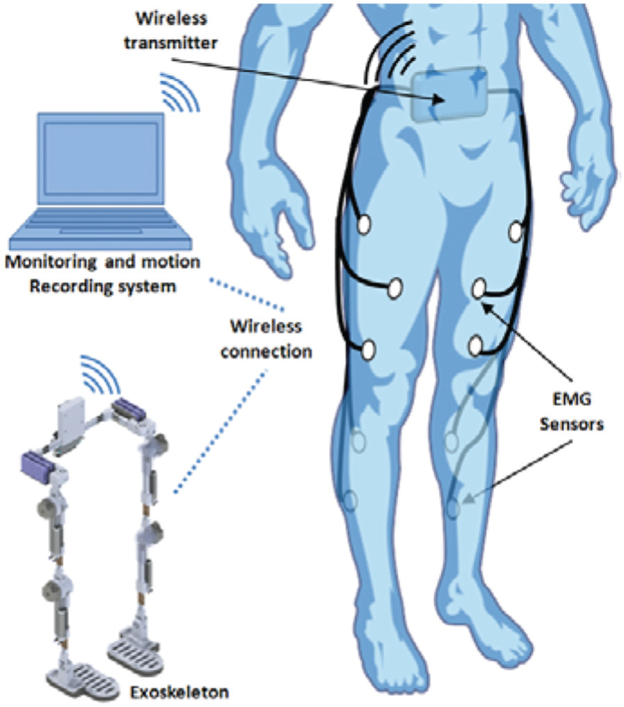
The human–machine interface (HMI) of this exoskeleton robot uses the EMG sensors (see Figure 5). They are put on several muscles of human lower limb and send EMG signals to the computer in a wireless way. These sensors capture the movement of the lower limbs and generate a base of gait patterns. By analyzing the patterns, the control commands are sent to the actuators to move the exoskeleton robot.
EMG sensors on human lower limb.
For each leg, the measured muscles are the vastus lateralis and gastrocnemius. They represent the movements of the hip and knee joints. The movements of human joints are usually activated by several muscles. Flexion/extension of the hip joint is mainly actuated by the muscles of iliacus, psoas, rectus femoris, tensor fasciae latae, biceps femoris, and semitendinosus. The motion of human knee joint uses the muscles of biceps femoris, semitendinosus, gastrocnemius, rectus femoris, vastus lateralis, and vastus medialis. The motion of human ankle joint is mainly actuated by the muscles of gastrocnemius, soleus, and tibialis anterior. The gastrocnemius muscle works on both knee joint and ankle joint.
In order to obtain lower limb motions by muscles’ activities, we put eight EMG sensors on one leg (see Figure 6). The relationships between the muscle groups and motions are (1) tensor fasciae latae, (2) adductor longus, (3) rectus femoris, (4) vastus lateralis and tibialis anterior, (5) vastus medialis, (6) biceps femoris, (7) gastrocnemius, and (8) soleus.

Eight EMG sensors on one leg.
These eight EMG signals are filtered, recorded, and sent to a classification algorithm to generate different motion patterns. These patterns give the desired angular position and angular velocity for each joint. This HMI uses the patterns from muscle fibers to predict the intention of the operator.
Hybrid actuator
We use hybrid pneumatic-electric system for the exoskeleton joints. It takes the advantages of both actuators. The harmonic drive actuator has a high torque, high accuracy position, and relatively small dimensions. These properties are ideal for gait rehabilitation because in the gait cycle the lower limb repeats similar actions. It is especially suitable for the rehabilitation and recovery of weak and injured people.
The hip and knee sagittal plane motions can be regarded as revolute joints. The harmonic drive actuator is mounted on a nylamid machined piece with mechanical stops to limit the range of motion. The mechanisms are coupled through six holding screws to fix the pulley to the harmonic drive’s axis.
The structure of a harmonic drive is shown in Figure 7. There are three components of the transmission rotate at different speeds and in the same axis of rotation. They are flex spline, wave generator, and circular spline. The external teeth of the flex spline mesh with the internal teeth of the circular spline along the major axis of the ellipse of the wave generator. The mechanism of the harmonic drive is that the wave generator has the engagement area on its axis when this area is moved

Structure of harmonic drive (http://harmonicdrive.net/).
PAMs are lightweight and have high power/weight ratio compared with the other actuators 16 (see Figure 8). The intrinsic elasticity (compliance) provides compliant actuation, and it is specially for people who have involuntary muscle contractions due a neurological disorder. 17 A double groove pulley connected to two PAMs is employed to construct a transmission based on the Bowden cables. One side of the Bowden cables is fixed on the top of each muscle, and the other side is fixed at the bottom of the adjustable link of the exoskeleton. The PAMs are driven by an array of electrovalent, which is fixed on the waist link. Each muscle includes a pressure sensor and a linear motion sensor for position transformation sensing. The diameter of the muscle is 30 mm. The contracted length is 210 mm, and the maximum length is 290 mm.

Pneumatic muscle actuators.
Hybrid actuation of the lower limb exoskeleton
PAM
The PAM is very similar to the action of human muscle. The human muscle can be approximated by a three-element phenomenological model.
18
They are parallel arrangement of contractile element, damping element, and spring element (see Figure 9). PAM can be regarded as a pendulum. The coefficients of each element can be expressed by a function of internal pressure


(a) Three-element phenomenological model for the PAM and (b) antagonistic PAM configuration and parameters.
where

The pressure

The antagonist configuration is shown in Figure 9(b). Here, the connection line rigidly attaches to the pulley to prevent slipping. If the radius of the two muscles connected around double groove pulley is

where

where
Harmonic drive actuator
The mechanism of harmonic drive has high ratios and high position accuracy. It has a wave generator. 19 The rigid steel core is elliptical in shape with very small eccentricity. 20 It is surrounded by a flexible race ball bearing. The flexible spline (or flexible) is a thin-walled hollow cup made up of alloy steel. External gear teeth are machined at the open end of this cup, and the closed end is connected to the output shaft (see Figure 10(a)).

(a) Mechanism of the harmonic drive and (b) equivalent mechanism.
In this article, the harmonic drive actuator has an absolute encoder resolution of 800,000 p/rev, with a gear ratio reduction of

where
The model of each servomotor can be divided into electrical and mechanical subsystems. The electrical system is based on Kirchhoff’s voltage law

where
The mechanical subsystem is

where

where
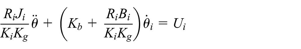
Equation (5) describes the dynamic of actuator. Finally, the harmonic drive model is
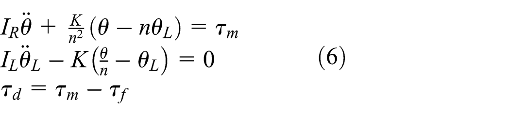
where
The torque
Controller design with the hybrid actuation
Since the main rotation of hip and knee joints during gait cycle occurs in the sagittal plane, the hip and knee joints of the exoskeleton are only actuated over the sagittal plane. 22 The ankle joint is not actuated. We use the Euler–Lagrange formulation to model each leg. Here, we use double-pendulum model as shown in Figure 11. The dynamics of the lower limb exoskeleton is


Double-pendulum model for the exoskeleton.
where
The harmonic drive actuator and the pneumatic muscles are applied to the joints in parallel. Our goal is to design a controller to couple efficiently the dynamics and obtain the best performance of the exoskeleton.
where
The control scheme is shown in Figure 12. The harmonic drive torque


Control scheme.
where
The pneumatic muscle torque
Admittance control with EMG
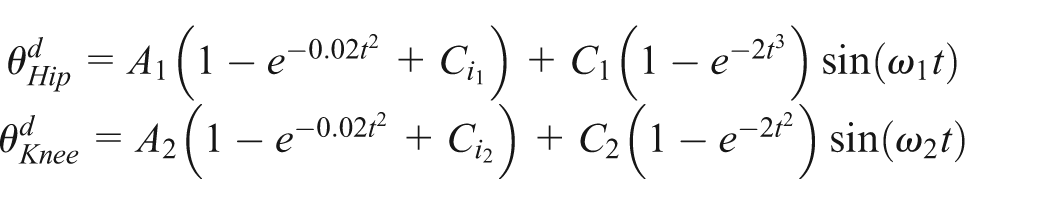
The object of admittance control is to generate reference trajectories
We use the EMG sensors to generate reference position
where

where
The traditional impedance control is

where

behaves like a target impedance.
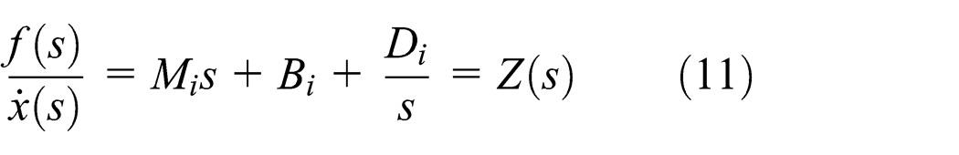
The impedance control (11) can generate reference signal as

Equation (12) is called as impedance filter. The impedance characterization of the human leg and biomechanical data can help us to select the right inertia and damping parameters
The admittance relation (11) generates reference as

It has the same form as PID control, and the control parameters can be chosen based on the kinematics and dynamics of the human arm.
The impedance or admittance control involves three components: rigidity, damping, and inertia. These components reflect the biomechanical characteristics of the tremor in the lower limb. If the arm and exoskeleton device are moving together perfectly, the force between the user and the device should be zero.
The musculoskeletal system (each joint of the lower limb that contributes to the tremor) can be modeled as a second-order biomechanical system. It is known that the frequency response of a second-order system presents the behavior of a low-pass filter. The cut-off frequency of this filter is directly related to the biomechanical parameters of the second-order system.
Experiment results
The computer control system of our lower limb exoskeleton has Intel Pentium 4 with 2.4 GHz processor and 2G RAM. The operation software is in Windows XP with MATLAB 7.2 + WinCon. The real-time control programs also operated in real-time target. All of the controllers employ a sampling frequency of 10 Hz.
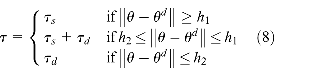
The two torques
where
The controller switch constants
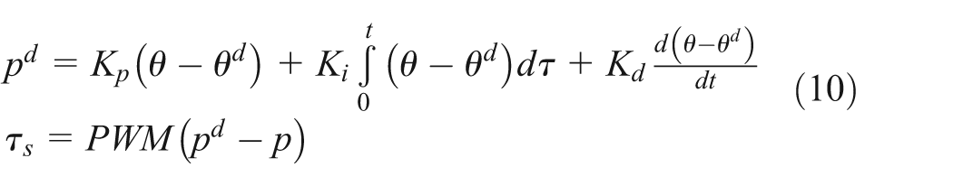
The PID law in time domain (9) or (10) can be transformed into frequency domain

where
We use the Ziegler–Nichols method to determine the parameters
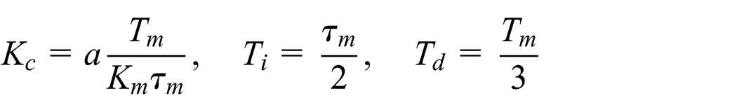
where
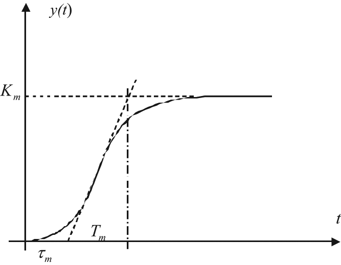
Step response of a linear system.
In order to show the effectiveness of the combination of PAM and DC motor, we do the following three tests for the hip joint to show the torques and tracking errors:
Pure PAM control as in equation (10);
Pure DC motor control as in equation (9);
Combination of PAM and DC motor as in equation (8), where
The tracking errors and the torques of the PAM control and DC motor control are shown in Figures 14 and 15. The combination results are shown in Figures 16 and 17. We can see that the hybrid actuation (Figure 15) can decrease the tracking error of the pure PAM control, and at the same time, it can increase the torque of the pure DC motor control. Although the tracking errors of the hybrid actuation at

Tracking errors of the PAM control and DC motor control.

Tracking error of the hybrid actuation.

Torques of the PAM control and DC motor control.

Torque of the hybrid actuation.
For the knee joint, we have similar results. Only the angles and the torques are smaller than the hip joint.
Conclusion
In this article, we proposed a novel design for the lower limb exoskeleton. We combine two different types of actuators: DC motors with the harmonic drive and the PAMs. By effective combination, we can take advantages of the two types of actuations. The high air pressure of PAM generates enormous force, while the harmonic drive actuator provides high regulation accuracy. The experiments and analysis show that this exoskeleton is ideal for the force augmentation, and the dimension is relatively small. It is suitable for the cyclical rehabilitation. Further work is to study the robot exoskeleton together with person.
Footnotes
Acknowledgements
The authors would like to thank Rogelio Lozano, in UMI-LAFMIA 3175 CNRS, for his help to design the robot exoskeleton.
Academic Editor: Yong Chen
Declaration of conflicting interests
The authors declare that there is no conflict of interest.
Funding
This research received no specific grant from any funding agency in the public, commercial, or not-for-profit sectors.