
Abstract
We developed a pneumatic robot arm driven by pneumatic actuators as a versatile end effector for material handling systems. The arm consists of a pneumatic hand and pneumatic wrist. The hand can grasp various objects without force sensors or feedback control. Therefore, this study aims to control the wrist motions to expand the hand motion's space. The hand mimics the human hand shape and can grasp objects that have different shapes and mechanical characteristics. The wrist has redundant degrees of freedom. This is useful when the robot moves to avoid obstacles. However, the drive mechanism of the wrist has nonlinearity from a mechanical viewpoint. Also, the pneumatic actuators used as the drive source have hysteresis characteristics. These features make the wrist motions difficult to control. Because the wrist is used in material handling systems, its motions need to be freely controlled. Therefore, in this research, experimental models of the drive system of the pneumatic robot wrist have been constructed. With the constructed models, the control systems were designed through simulations. After that, we attempted to control the wrist motions with the constructed controllers.
As a result, the wrist models are coincident with wrist motions. Finally, experimental results were obtained that match the simulation results.
1. Introduction
The population of Japan has started to decrease, leading many in the country to be concerned about its labour force shrinking. In industrial fields, automation of the factories is one way to make up for reduced man power [1]. This leads to other advantages such as making production more efficient and cutting labour costs [2]. Various robots have been used in factories, for example, welding robots and material handling machines in car factories [3–4]. However, the work robots can perform is limited and there are difficulties adapting these to different environments. This is because most factory robots are controlled by only sequence control. For instance, material handling robots move their end effectors to a specified position, grasp known objects and move the objects to the next specified position. Using only sequence controllers, it is difficult for the robots to work depending on the time and situation. Because of this, the robots cannot adapt to sudden changes in circumstances. To solve this problem, we need to focus on hardware and software. In terms of hardware, we have to develop end effectors that can grasp various things. In terms of software, we need to combine image-recognition techniques with feedback and sequence control techniques [5]. We expect that these combined techniques will enable material handling robots to perform more tasks.
We previously developed a pneumatic robot arm driven by pneumatic actuators as a versatile end effector. This arm consists of a pneumatic hand and pneumatic wrist. The hand's shape is similar to the human hand and it can grasp objects that have different shapes and mechanical characteristics [6]. However, the wrist has redundant degrees of freedom. This is useful when the robot moves to avoid obstacles. However, the drive mechanism of the wrist has nonlinearity from a mechanical viewpoint. Also, the pneumatic actuators used as the drive source have hysteresis characteristics. These features make the wrist motions difficult to control [7]. Because the wrist is used for handling materials, its motions need to be freely controlled. Therefore, in this research, we constructed experimental models of the drive system of the pneumatic robot wrist. With the constructed models, we designed the control system through simulations. After that, we attempted to control the wrist motions with the constructed controllers.
2. Pneumatic Robot Arm
In previous research, we developed a pneumatic robot arm as a versatile end effector. The broad overview of this arm is shown in Fig. 1. The detail view of this hand is shown in Fig. 2. This arm is composed of a pneumatic hand and a pneumatic wrist, and we used McKibben pneumatic actuators as the drive source. These actuators generate force in response to applied pressure; their constitution is shown in Fig. 3. This pneumatic actuator has a dual structure of an internal membrane and external shell. When the internal membrane is inflated with compressed air, the pressurized gas pushes against its external shell, increasing its volume. The muscle radius increases and together with radial expansion, the muscle contracts axially and exerts a pulling force. Also, the generative force of a pneumatic actuator depends on the air pressure and shrinkage ratio [8], and these pneumatic actuators are driven by low pressure up to 0.2 MPa [9].
The actuators used in this research are divided into two main groups. The first one is a regular pneumatic actuator, which is between 18-45 mm. Its maximum generative force is 14–25 N. This pneumatic actuator is smaller than the conventional one, therefore, through fitting this actuator to a set of fingers of a robot hand, it can move knuckles directly [10]. Moreover, a robot hand consists of 13 regular pneumatic actuators and possesses five fingers, similar to a human hand. Meanwhile, fitting a spring on the back side of a finger enables the finger to expand. In this way, a pneumatic hand can grasp soft, fragile objects, such as eggs, without force sensors on the fingertips because of the compliance characteristics of the pneumatic actuators [11].
The second one is a power pneumatic actuator which is about 70 mm. Because this actuator is larger than the first one, it has higher generative force and is used to move parts with higher power. For this reason, in a pneumatic robot arm, four power pneumatic actuators are used to drive the wrist and one is used to adduct the thumb. Furthermore, antagonistic configuration of power pneumatic actuators at the wrist enables the wrist to perform various movements, such as palmar flexion/dorsal flexion or radial deviation/ulnar deviation. The mobile region of this wrist is 30 deg in the palmar flexion/dorsal flexion, 20 deg in radial deviation and 25 deg in ulnar deviation. In this research, we aim to control this wrist motion.

Pneumatic Robot Arm

Detailed View of Pneumatic Hand

Mechanism of Pneumatic Actuator
3. Electro Pneumatic Regulator
In this study, we used an electro pneumatic regulator and a compressor to send air into the pneumatic actuator. The regulator regulates evacuation pressure in accordance with the command voltage signal. This section explains the characteristics of the regulator. Experimental conditions are determined in which the pressure provided from a compressor is 3 MPa and the piping length between the regulator and pressure sensor (PSE 530; SMC) is 2 m. The command signal is changed from 0 to 4 V by 0.5 V intervals. Results obtained by a command signal of 3 V are shown in Fig. 4. These results reveal the establishment of the pressure by the regulator takes some time. By modelling the characteristics of the regulator with the experimental results, we attempted to apply the model to a simulation.
First, the steady-state characteristics of the electro pneumatic regulator are explained. On the basis of the data obtained from the preceding section, Fig. 5 shows a graph in which the horizontal axis is command voltage and the vertical axis is steady-state pressure. It reveals that the voltage is proportional to the steady-state pressure. The relationship is expressed as follows:

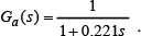
In this function, P means pressure and v means input voltage. Second, the transient property of the electro pneumatic regulator is explained. As above, the evacuation pressure of a regulator takes 10 sec to reach a steady-state value, therefore, we attempted to describe the transient property of the regulator with the first order lag system. The lag system is expressed as below:

In this function, κ means gain and T means time constant. Gain is determined to be 49.4 from Eq. 1. In this study, we move the pneumatic wrist after applying 100 kPa to the two antagonistic actuators in it, therefore, we apply 100 kPa to the actuators as an initial pressure. Then we input a constant pressure. After that we return pressure to 100 kPa. Through this task, the time constant was determined to be 0.111 and the first order lag model is complete. Fig. 6 compares the simulation results of the first order lag model with experimental results when the command voltage is 3 V. This figure shows that the electro pneumatic regulator cannot be fully modelled by the first order lag model. Because of this, a new model is needed that behaves more precisely than the first order lag model. The electro pneumatic regulator obviously needs to be controlled in some way, therefore, we attempted to model the regulator with a proportional (P) controller, which is the easiest control system. The system of the regulator is expressed as below:


We assume that the system of the regulator is as shown in Fig. 7. In this system,

The same formula with the first order lag model is obtained if

We name this model the “variable P control model”. Fig. 8 shows simulation results obtained from the variable P control model. This figure indicates that these results are closer to the experimental results than the results with the first order lag model. Therefore, in this research we model the electro pneumatic regulator with variable P control.

Output of Electro-pneumatic Regulator (3V)

Relationship between Applied Voltage and Steady-state Pressure

Simulation with First Order Lag Model (3V)

Block Diagram of P Control System in Regulator

Simulation with Variable P Control Model (3V)
4. Experimental Apparatus
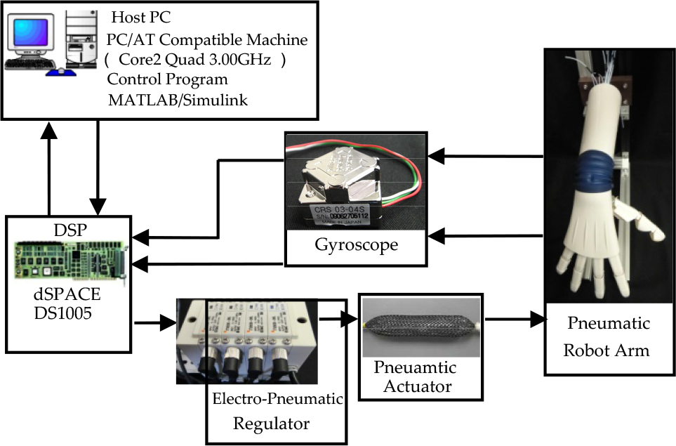
Fig. 9 schematically illustrates the experimental apparatus. We used a PC/AT compatible machine to build programs and monitored the experimental data on MATLAB/Simulink, connecting the machine to the DSP (dSPACE 1005) with ISA buses to receive the sensor data and send the control signals to the electro pneumatic regulator (IITV00-04; SMC). The experimental environment made it possible to carry out the control experiment with a 1-ms sampling period. The analogue control signals converted by the DSP's D/A board were sent to the motors through the motor driver.
The air pressure provided by the electro pneumatic regulator was sent to the antagonistic actuators of the pneumatic robot arm. This made each actuator expand and contract, enabling the wrist to move in various ways. To measure the angle of the wrist, gyro sensors (CRS03-04; Silicon Sensoring Japan) were fixed on the back and lateral side of the hand. The angle data from these sensors were converted by the A/D board of the DSP and shown on a PC monitor.
Experimental Apparatus
5. Modelling Of Pneumatic Wrist
5.1. Initial Motion Model of Pneumatic Wrist
To comprehend initial motion systems of the wrist, pressure (0 kPa-200 kPa by 50 kPa) was applied to the actuators after 100 kPa had been applied as an initial pressure. The results for palmar flexion/dorsal flexion and radial deviation/ulnar deviation are shown in the left and right graphs, respectively, in Fig. 10. In these figures, the horizontal axis is applied pressure and vertical axis is the steady-state wrist's angle. These figures proved that initial motions of the wrist had a dead zone around 100 kPa.
Relationship between Applied Pressure and Steady-state Angle of Wrist
5.2. Several Motions of Pneumatic Wrist
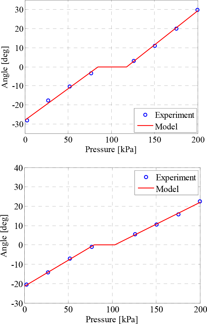
After applying initial pressure (100 kPa), we changed the applied pressure by 50 kPa in a staircase pattern. (Fig. 11) The results of palmar flexion/dorsal flexion and radial deviation/ulnar deviation are shown in the left and right graphs, respectively, in Fig. 12. In these figures, the horizontal axis is applied pressure and vertical axis is steady-state wrist angle. These figures indicate that both motions have hysteresis characteristics. This means that the angle of the wrist varies in spite of the same pressure being applied depending on the context. Moreover, they indicate that characteristics change depending on the actional direction of the wrist. Using these characteristics, we attempted to model the wrist. We put this hysteresis loop into four segments. The right and left segments in the hysteresis loop are defined as lines 1 and 2, respectively.
Lines 1 and 2 are obtained when the wrist moves in the plus direction (dorsal flexion or ulnar deviation) and the minus direction (palmar flexion or radial deviation), respectively. The straight line transits in a constant slope between lines 1 and 2.
For palmar flexion/dorsal flexion, the lines are expressed as follows:
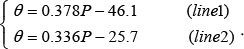
The slope of the straight line that transits between the lines is determined to be 0.0803.
For radial deviation/ulnar deviation, the lines are expressed as below:

The slope of the straight line that transits between the lines is determined to be 0.0557. θ and ψ are the angle of the wrist.
Therefore, in this research, we name the model a “hysteresis model”. Moreover, the initial motion model and the transient property of the wrist are added to the hysteresis model. The transient property is expressed by the first order lag model.
The pneumatic wrist model includes this transient property. The electro pneumatic regulator model and the wrist model were combined and named the “wrist drive system”. We ran a simulation of this system and compared the results with those from the experiment. The results of palmar flexion/dorsal flexion and radial deviation/ulnar deviation are shown in the left and right graphs, respectively, in Fig. 13. The results of radial deviation/ulnar deviation were less coincident with the experiment data than those of palmar flexion/dorsal flexion. This is because errors were generated when we approximated the hysteresis model with four segments in radial deviation/ulnar deviation. However, in both motions, the hysteresis model was relevant enough to validate the simulation.
Therefore, the control system was constructed by adopting these models as a pneumatic wrist model.

Relationships between Applied Pressure and Time

Hysteresis Loop of Pneumatic Wrist Motions

Simulation of Pneumatic Wrist Motions
6. Controllers
6.1. PI Controller
After it was provided with a constant pressure, the pneumatic wrist did not necessarily revert to the first position even though the previous pressure is reapplied. This was because pneumatic actuators have hysteresis characteristics. To make up for this phenomenon, we controlled this wrist with a PI controller. The control output is expressed as follows:
where
The control performance of PI controller was determined by two kinds of gain


where
For several motions,
7. Control Experiments
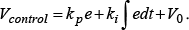
We aimed to keep the wrist constant by inputting a step signal (15 deg). We used a PI controller as the control system.
7.1. Palmar Flexion-Dorsal Flexion
Fig. 14 shows the palmar flexion/dorsal flexion experimental and simulation results. This figure shows that experimental results are similar to the simulation results, therefore, the model could precisely express the palmar flexion/dorsal flexion.
Results of Fixed Command Control (Palmar Flexion/Dorsal Flexion)
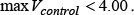
7.2. Radial Deviation-Ulnar Deviation
Fig. 15 shows the radial deviation/ulnar deviation experimental and simulation results. This figure shows that there are errors at about 6 sec between the experimental results and the simulation results. This is because of the errors that were generated by linearizing the hysteresis loop. In spite of these errors, because control results required simulation conditions, sufficient control results could be obtained.
Results of Fixed Command Control (Radial Deviation/Ulnar Deviation)
8. Conclusion
In this research, we developed a system with a pneumatic robot arm for application to material handling in industrial fields. We constructed the control system of the robot's wrist and tested it in a control experiment. The following conclusions were drawn:
1) We tested an electro pneumatic regulator and the characteristics were expressed with a model using a variable P controller.
2) For several motions, performance characteristics of the wrist are expressed with a model that was obtained from comprehending its hysteresis characteristics and transient properties.
3) We constructed a feedback control that included the electro pneumatic regulator's model and pneumatic wrist's model. Then, we designed a PI controller through simulations.
4) The controlled experiment of the designed controller indicated that experimental results could be obtained that match simulation results.
Footnotes
9. Acknowledgments
This study was partially supported by Grant-in-Aid for Scientific Research (A)(23246041), Japan Society for the Promotion of Science.