
Abstract
This paper describes development of a three somites earthworm type mobile inspection robot which is able to move in long pipes. We have many small diameter pipes which are gas or water pipes for individual or corporate houses and boilers or hot water pipes for industries. They are settled in the ground horizontally or in the narrow spaces vertically and some of them are covered by casings or hard heat insulating matters. It is very difficult to inspect from out of the pipes. If we can insert a mobile inspection robot into the pipes from the suitable position, we are easy to inspect the pipes. Authors fabricated a three somites earthworm type mobile inspection robot in which we use three rubber bellows as pneumatic actuators. Sixteen rubber friction rings are used to get friction force between pneumatic actuators and the pipes. The electromagnetic valves and air-feeding tubes for the pneumatic actuators are carried on trolleys in order to decrease friction force between the pipes and them. The fabricated three somites earthworm type mobile inspection robot can move in a pipe which is 78 mm in inner diameter and vertical pipe carrying a load that is equivalent to the air-feeding tube of 32 m length. Consequently, the inspection robot was confirmed to move in the long pipes.
Introduction
A few years ago, we had an accident that radioactive cooling-water flowed out from the primary cooling-water pipe of an atomic power plant in Japan. The cooling water pipe whose inner diameter is 76 mm was cracked by vibration of the cooling-water. The cracked location was inspected after removal of heat insulating materials around the pipe. If we can insert an inspection robot and inspect the pipe, we are avoidable from the difficult removal of the heat insulating materials and radioactivity of the flowed water. The cooling-water pipe is 76 mm in inner diameter, about 30 m long and has some elbows and vertical parts. Robots driven by electric motor are difficult to move in the vertical pipes, because the ratio between the power and the weight of the electric motor is not large (Miyagawa et al., 1994; Kawaguchi et al., 1997).
Authors have researched a new inspection robot which is able to move in the long pipe which has some elbows and vertical parts and driven by pneumatic actuators, because the pneumatic actuators are advantageous concerning the ratio between the power and the weight. However, they could not move the long distance (Noritsugu et al., 2000; Kato et al., 1997; Takahashi et al., 1995; Kato et al., 2000; Ono et al., 2001). This is due to the compressibility of the air.
We fabricated an artificial earthworm type robot in which we use three rubber bellows as pneumatic actuators. Twenty rubber friction rings are used to get friction force between bellows and the pipe. Three electromagnetic valves which control pneumatic pressure to the three bellows are attached direct behind of the robot in order to evade the flowing-lag of the pneumatic pressure. The electromagnetic valves and air-feeding tubes are carried on trolleys in order to decrease friction force between the pipe and them. The robot was confirmed to move in the pipe which has 8 elbows and 32 m long.
Structure of fabricated robot and characteristics of its elements
Structure of fabricated robot
An in-pipe mobile robot which is able to move in pipes whose inner diameter is 76 mm is shown in Fig. 1. An actual diameter of the pipe is 79 mm. The robot is constructed by three bellows for the pneumatic actuators, friction rigs and three electromagnetic valves. Outer diameter, inner diameter and natural length of the bellows are 60 mm, 43 mm and 145 mm, respectively. The bellows are made of Nitrile Butyl Rubber. Total 12 friction rings are attached at the end of the three bellows as moving legs of robot. The friction rings are 84 mm in outer diameter, 42 mm in inner diameter and 1.5 mm thick. When the friction ring is attached at the bellows, the inner diameter is enlarged, because the inner diameter of the friction ring is 3 mm smaller than the inner diameter of the bellows. Then, friction ring comes to the shape of a cone. Three electromagnetic valves which feed pneumatic and vacuum pressure are attached atdirect behind of the actuators. Consequently, the electromagnetic valves move with the actuators. An air-feeding tube made of polyurethane (inner diameter is 4 mm) is attached to the electromagnetic valves in order tofeed pneumatic pressure. Another air-feeding tube (inner diameters is 4 mm) are attached to the electromagnetic valves in order to feed vacuum pressure. A power line for the electromagnetic valves is bundled with air-feeding tubes. They are 40 m long.

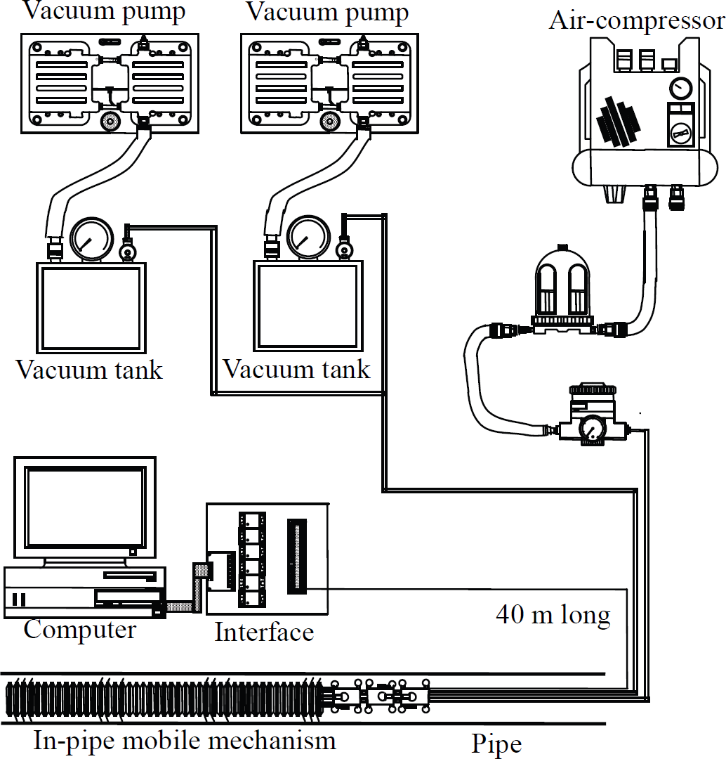
Structure of in-pipe mobile robot system
The air-feeding tubes are carried on conveying mechanisms in order to decrease friction force between the pipe and them. Cross-section of the air-feeding tubes conveying mechanism is also shown in Fig. 1. The air-feeding tubes conveying mechanism consists of a chassis made of vinyl chloride pipe, 8 legs made of aluminum and 8 wheels made of plastics. The wheels smoothly rotate. The air-feeding tubes conveying mechanism can carry the air-feeding tubes in pipe whose inner diameter is more than 74 mm.
System of fabricated robot
Fabricated robot system is shown in Fig. 2. Moving sequence is programed in a computer. The computercontrols the electromagnetic valves which are 40 m far away through a valve controller, using the air-feeding time schedule program for the actuators. The other ends of air-feeding tubes are attached to the air-compressor and the vacuum pump.
In-pipe mobile mechanism system
The bellows are elastic. The force generated by the elasticity of the bellow depend on the displacement of the bellows. The relationship between the force and displacement is shown in Fig. 3. The force is positive in the small displacement and negative in the large displacement. Forces generated by pressure difference are shown as


where, p1 is the internal pressure of the first bellows, p2 is the internal pressure of the second bellows, p3 is the internal pressure of the third bellows and pa is atmospheric pressure. S is the effective cross-sectional area of the bellows and is 1.86 × 10⁻³ [m2].

The relationship between the force and displacement
Friction force between pipe and the friction rings which act the legs of the robot is measured. The measured force is shown in Fig. 4. Forward direction force and backward direction force are 12 N and 28 N, respectively in the case of 3 friction rings. Roughly speaking, the friction force is proportional to the number of friction rings, and the backward direction force is 2 times of the forward direction force.

Friction ring characteristics and displacement
Pressure supplying and internal pressure of the bellows
The time chart of pressure supplying to the bellows is shown in Fig. 5(a). “P” is shown as positive pressure supplying and “V” is shown as negative pressure supplying. “τ1” is the time of positive pressure supplying and is 1.5 s. “τ2” is the time of negative pressure supplying and is 7 s. These “τ1” and “τ2” are needed for the bellows to stretch and to shrink enough. The internal pressure of the bellows is shown in Fig. 5(b). The positive pressure in three bellows is about +10 kPa and the negative pressure in three bellows is about −40 kPa.

Time chart of pressure and internal pressure of the bellows
A dynamic balance model of the robot is shown in Fig. 6. In the Fig. 6, after the initial condition that all three bellows are shrunk, the stretching of the first bellows by the rising of internal pressure is shown in (a). This stage is called as Step 1. After the Step 1, the first bellows is shrunk and the stretching of the second bellows by the rising of internal pressure is shown in (b). This stage is called as Step 2. After the Step 2, the second bellows is shrunk and the stretching of the third bellows by the rising of internal pressure is shown in (c). This stage is called as Step 3. After the Step3, the shrinking of the third bellows by the vacuum pressure is shown in (d). This stage is called as Step 4.

Force balance of the microrobot
In the figure, p1 is the internal pressure of the first bellows, p2 is the internal pressure of the second bellows, p3 is the internal pressure of the third bellows and pa is atmospheric pressure. B1 is a force generated by the elasticity of the first bellows, B2 is a force generated by the elasticity of the second bellows and B3 is a force generated by the elasticity of the third bellows.
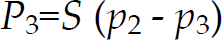
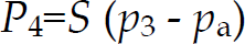
In the figure, P1 is the force by pressure difference at the front wall of the first bellows, P2 is the force by pressure difference at the wall between the first bellows and the second bellows, P3 is the force by pressure difference at the wall between the second bellows and the third bellows, and P4 is the force by pressure difference at the rear wall of the third bellows.
In the figure, F1 is the friction force of the first friction rings, F2 is the friction force of the second friction rings, F3 is the friction force of the third friction rings and F4 is the friction force of the fourth friction rings. The friction force of all friction rings acts to prevent the moving of the bellows. A mass of the front part of the bellows involved friction rings is 0.3 kg. The acceleration of the bellows is considered to be less than 0.1 m/s2. Then the inertia forces of the bellows are negligible, because the inertia forces are less than 0.03 N. The mass pulled is M and the traction force needed is W.
Consequently, the force balance equations of the robot are shown as follows.
(a) in the case of stretching of the first bellows (= Step 1)


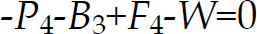
(d) in the case of shrinking of the third bellows (= Step 4)


The force balance equations of the robot in the case of (b): Step 2 and (c): Step 3 are neglected, because they are shown almost the same as the case of (a) and (d).
Moving principle of in-pipe robot is shown in Fig. 7. All friction rings are at the condition of the forward direction when the robot is inserted into the pipe. At Step 0, All bellows are shrinking by the negative pressure. At Step 1, the positive pressure is supplied to the bellows-1. Then the bellows-1 is stretched. The front friction rings of bellows-1 slips, because the friction force (F2+F3+F4) of friction ring −2,−3,−4 in condition of the backward direction is larger than the friction force (F1) of friction ring-1 in condition of the forward direction. Consequently the head of bellows-1 goes to forward direction.

Moving principle of in-pipe robot
At Step 2, the negative pressure is supplied to the bellows-1 and the positive pressure is supplied to the bellows-2. Then the bellows-1 is shrunk and the bellows-2 is stretched. The front friction ring-2 of bellows-2 slips, because the friction force (F1+F3+F4) of friction ring-1,-3,-4 in condition of the backward direction is larger than thes friction force (F2) of friction ring-2 in condition of the forward direction. Consequently the tail of bellows-1 and the head of bellows-2 go to forward direction.
At Step 3, the negative pressure is supplied to the bellows-2 and the positive pressure is supplied to the bellows-3. Then the bellows-2 is shrunk and the bellows-3 is stretched. The front friction ring-3 of bellows-3 slips, because the friction force (F1+F2+F4) of friction ring-1,-2,-4 in condition of the backward direction is larger than the friction force (F3) of friction ring-3 in condition of the forward direction. Consequently the tail of bellows-2 and the head of bellows-3 go to forward direction.
At Step 4, the negative pressure is supplied to the bellows-3. Then the bellows-3 is shrunk. The rear friction ring-3 of bellows-3 slips, because the friction force (F1+F2+F3) of friction ring-1,-2,-3 in condition of the backward direction is larger than the friction force (F4) of friction ring-4 in condition of the forward direction. Consequently the tail of bellows-3 goes to forward direction. Step 4 is same as Step 0 of the initial condition. One cycle of the moving ends. The robot goes the displacement between shrinking and stretching to the forward direction. The cycle returns to Step 1 from Step 4 and continues. The robot is able to move by continuing the moving cycle.
A pipe for moving experiment
A pipe for moving experiment is shown in Fig. 8. The pipe consists of 7 m horizontal straight stainless steel pipes and “U” letter curving pipes which are connecting double elbows. The “U” letter curving pipe is 1.5 m long and 300 mm in radius of curvature. The elbows are made of transparent vinyl chloride and exist in vertical plane. Consequently the robot cannot pass the elbows, if the robot can move to vertical direction.

The pipeline for an experiment
Traction force is made at the Step 4. In this time, Eqs. (9), (10), (11) and (12) must be satisfied simultaneously.

In the Eq. (13), (P1−P2−P3−P4) =0.
Then,

Maximum friction forces shown in Fig. 4 are not be expected, because 3 friction rings do not act when they are shrinking. Measured traction force to upward direction is shown in Fig. 9. The traction force is confirmed to depend on the force difference (F1+F2+F3−F4). The traction force of 50 N was obtained concretely in the case where 12 friction rings were used to move the robot.

Relationship between friction ring and traction force
Friction force of the air-feeding tubes conveying mechanism in the pipe was measured. Space between each mechanism was selected as 500 mm, 750 mm and 1000 m.
Horizontal straight pipe
Friction force is constant and 0.41 N/m at any space of mechanisms.
“U” letter curving vertical pipe
Friction force depends on space of mechanisms, and is 12.6 N at 500 mm, 18.1 N at 750 mm and 24.7 N at 1000 mm. Relationship between the friction force and the moving distance of the robot is shown in Fig. 10. Friction force for the robot to move 30 m (passing of 8 elbows) may be 42 N, if we choose the space of the mechanisms to be 500 mm. Consequently the robot attached 12 friction rings is expected to move more than 30 m.

Characteristics of tube conveying mechanism
Relationship between moving speed and moving distance is shown in Fig. 11. The moving speed decreases according to the increasing of the moving distance. However, moving speed is 13 mm/s at 30 m. Finally, maximum moving distance was confirmed to be 32 m.

Relationship between moving speed and distance
We fabricated an artificial earthworm type mobile inspection robot which is constructed by three bellows, 12 friction rings and three electromagnetic valves.
The robot was confirmed to move in the pipe which has 8 elbows and is 79 mm in inner diameter and 32 m long.
The traction force depends on the number of friction rings. The increasing to 20 friction rings may be able to move more than 40 m. We obtained feasibility on an in-pipe inspection robot of the primary cooling-water pipe of atomic power plant.