
Abstract
To describe the characteristics of thermally induced coupled micro-motions more exactly, a numerical model is proposed for a satellite system consisting of a rigid body and the complex appendages. The coupled governing equations including the effects of transient temperature differences are formulated within the framework of the Lagrangian Method based on the finite element models of flexible structures. Meanwhile, the problem of coupling between attitude motions of rigid body and vibrations of flexible attachments are addressed with explicit expressions. Thermally induced micro-motions are examined in detail for a simple satellite with a large solar panel under the disturbance of thermal environment from earth shadow to sunlight area in the earth orbit. The results show that the thermal–mechanical performances of an on-orbit satellite can be well predicted by the proposed finite element model.
Introduction
Thermally induced motions of a satellite with complex flexible appendages, which have a potential reverse effect on system performance, have attracted worldwide attention in engineering fields. For the on-orbit flexible appendages, the temperature differences, which are induced by the change of surrounding thermal environment, can result in elastic deformations due to different expansions or shrinkages. Additionally, these thermal responses can usually be classified into quasi-static deformations caused by slowly developing temperature differences, and dynamic structural motions caused by rapidly changing temperature differences. Meanwhile, the attitude rotations of the entire satellite may be induced by the thermal motions of flexible appendages. Therefore, to obtain the more accurate thermal response, it is necessary to investigate the modeling technologies on the coupled dynamics of entire satellite system disturbed by the change of thermal environment.
Since the basic concept of thermally induced micro-vibrations was first addressed to describe the motions of a cantilever beam by Boley, 1 a series of research works have been proposed to analyze the thermal–mechanical characteristics. Most of the investigations focused on the thermal responses of fixed appendage structures. Levine 2 described the Interferometry Program Experiments to investigate the potential thermal snapping when space structures undergo rapid thermal variations. Xue et al. 3 gave a finite element (FE) scheme to solve the problem of thermally induced bending-torsion coupling vibration of large space structures. Heuer 4 introduced alternative formulations of various higher order theories to offer complete analogies between the corresponding initial boundary value problems and those of homogenized single layer structures of effective parameters. Gupta and Sharma 5 proposed the method to solve the orthotropic trapezoidal plate of variable thickness with clamped-simply supported-clamped-simply (C-S-C-S) boundary conditions. Iwata et al. 6 performed a laboratory experiment with a scale model of the paddle and derived a FE analytical method to analyze the response for the Advanced Land Observing Satellite (ALOS). Rath and Sahu 7 gave the numerical investigation on the free vibration behavior of laminated composite plates subjected to varying temperature and moisture. Mohammadreza et al. 8 investigated the thermally induced vibration of a functionally graded (FG) cantilever micro-beam subjected to a moving laser beam via simulating the equivalent third-order dynamic system. Fan and Xiang 9 proposed a novel optimal design to minimize an index determined by the system characteristic thermal time and natural frequency by using a kind of Fourier-finite element method (FEM) technique and the Lanczos method. On the other hand, the attitude rotation induced by the thermal deformations of flexible structures has also been taken into account to make the further error budget of mission pointing accuracy. Based on the thermal quasi-static motions of flexible appendages, Dennehy et al., 10 Foster et al. 11 and Hail and De Kramer 12 given the coupled models to analyze the change of attitude motion for different spacecrafts. Based on the effect of thermal dynamic response, a coupled method was proposed by Johnston and Thornton13,14 to demonstrate the characteristics of the simple spacecraft consisting of a rigid body and a cantilevered beam. The formulated governing equations are suitable for the thermal response analysis of the satellite system with simple flexible structures. Due to the difficulty in obtaining the analytic resolutions, it is necessary to develop an efficient computation method to deal with the analysis problem of the satellite system with complex flexible appendages. Meanwhile, the total angular momentum of the system is conserved, which implies that the thermal response for complex flexible structures and attitude dynamics should be considered simultaneously to obtain simulation results more exactly.
Therefore, a numerical model is presented to analyze the characteristics of thermally induced coupled micro-motions of a satellite system consisting of a rigid body and complex flexible appendages. The coupled thermal governing equations, including the transient thermal effects, are formulated with explicit expressions of coupling items between attitude rotation and appendage vibration by utilizing the Generalized Lagrangian formulas. An application is shown to predict the thermal micro-vibrations of a simple satellite with a large solar panel under the disturbance of thermal environment from earth shadow to sunlight. The computational results are obtained by studying an application example to demonstrate the thermally induced dynamic response.
Mathematical model
The objective considered is to predict the coupled dynamic response of the satellite system (Figure 1) consisting of a rigid body and complex flexible appendages. The responses of flexible structures, which are assumed to be small deformations, are analyzed by the universal FEM. Three coordinate systems are utilized as follows: the orbit reference coordinate {

Simplified satellite model including a rigid body and universal flexible appendages.
System kinetic energy
In this section, the system kinetic energy will be obtained by utilizing the complex analytic methods in mechanics. Due to the scalar functions, the kinetic energy for flexible appendage and the rigid body will be shown in the reference coordinates {
The universal flexible appendage
Assume that dmai is one arbitrary node in the ith appendage structures, the radius vector from dmai to or in the coordinate {

where
Differentiating equation (1) with time once in the coordinate {

where
The kinetic energy of the ith flexible appendage in the reference coordinate {

where
The rigid body
Assume that dmb is one arbitrary node in the rigid body. The radius vector from dmb to or in the coordinate {

The velocity of dmb in the coordinate {

Hence, the kinetic energy of the rigid body in the coordinate {

where
The entire satellite system
By combining the equations (3) and (6), the kinetic energy of the entire satellite system can be calculated as

where
System potential energy
For the universal flexible appendage structures, Boley and Weiner 15 described the strain energy of the element including thermal effects as

where
Meanwhile, the relation between the strain field and the displacement vector of FE output nodes can be defined as

where

where the symbols
Therefore, after integrating all the flexible elements of the satellite system, the potential energy of the entire satellite system in the generalized coordinate {

where
Coupled dynamic equations
Combining the system kinetic energy with the potential energy, the Lagrangian function of the system can be obtained as
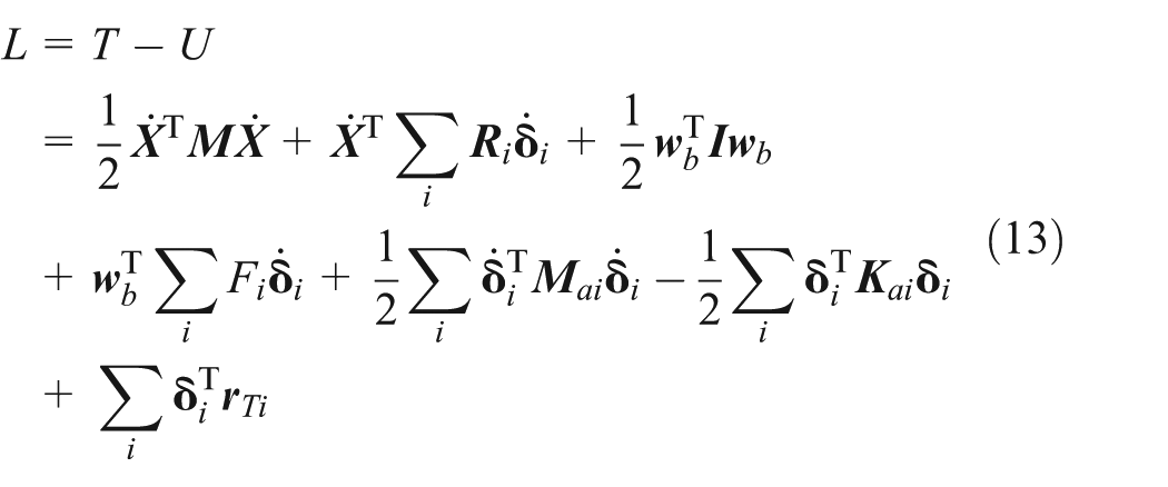
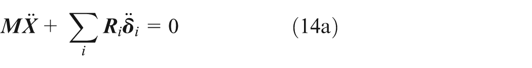
By utilizing the Lagrangian formula for the attitude motions in the satellite reference coordinate {


Numerical application
To testify the validity of the proposed coupled model, a numerical study is employed to investigate the thermally induced dynamics of a satellite with a single solar panel as shown in Figure 2. The geometry of solar panel consisting of three parts is presented in Figure 3. The orbit reference coordinate {

A simple satellite with a single solar panel.

Geometry size of the solar panel.
Transient temperature data of the solar panel
To obtain the thermal data of the solar panel more accurately and efficiently, the commercial software IDEAS TMG is used to simulate the orbit environment and calculate the temperature gradient. The physical and orbit parameters are adopted here as shown in Tables 1 and 2. To simplify the calculation, one thermal coupled channel is constructed to simulate the heat conductivity from the lighted side panel to the shadowed side panel. Here, the conductivity is to be 1.2 W/m °C.
Heat physical parameters.

Orbit parameters.

IR: infrared.
The eclipse transitions from earth shadow to sunlight area in the earth orbit are chosen for the further analysis. Figure 4 shows the time history of temperature for the middle point. It can be obviously seen that the temperature differences in the earth shadow area and in sunlight area are close to be constant, and the numerical values change rapidly at the time of exiting from earth shadow. During earth shadow or sunlight area, the solar radiation, which is the maximum thermal resources, induces the slowly developing temperature differences due to the normal direction of solar panel to sun. Meanwhile, the big temperature leap occurs when the solar radiation is to affect the solar panel suddenly.

Time history of temperature for the middle point.
Satellite dynamics response
In this part, the solution for the dynamic response of the satellite system with the disturbance of thermal environment will be discussed by using the proposed model.
An FE model based on the isotropy material is first constructed for the flexible solar panel. And the structural parameters are given in Table 3. For the case of the solar panel fixed on the left, the fundamental frequency can be obtained as 0.1158 Hz. For the further dynamic analysis, five flexible modes are used with a time step of 0.2 s.
Structural parameters.

The thermal load is achieved by combining the transient temperature and the FE model. With the assumption for the initial values to be zero, Figure 5 shows the time traces of bending moment for the middle point. It is obvious that the values of the bending moment around the axis y remain consistent with the change trend of transient temperature differences as shown in Figure 4, while the bending moment around the axes x and z belonged to the small level is not significant in Figure 5.

Time traces of the bending moment for the middle point.
The potential of thermally induced dynamic response can be analyzed by utilizing the key parameter proposed by Boley.
16
The thermal response time
Finally, the thermally induced motions of entire satellite system disturbed by thermal moment are analyzed in brief by utilizing the proposed equations. With the structural damping parameters being 5‰ and the mass moments of inertia of the three parts being 22,000 kg m2, 22,000 kg m2, and 20,000 kg m2, respectively. The thermal deformations of the middle point in the flexible solar panel and the induced attitude motions of the satellite can be obtained, as shown in Figures 6 and 7. It is obvious that the values of thermal motions are small: the maximum displacement of flexible panel can reach to the millimeter level, and the attitude angular displacement can reach to the milliarcsec level. The thermally induced motions of the flexible solar panel and the satellite’s attitude belong to the quasi-static deformations composed of small dynamic deformations.

Time history of the thermal displacements along the axis direction for the middle point.

Time history of the thermal angular displacement around the axis direction for the satellite’s attitude.
Conclusion
A numerical FEM for investigating the coupled mechanical characteristics of thermally induced motions of a satellite with large flexible appendages has been proposed in this article. The governing equations, taking the transient thermal effect into consideration, are obtained with the interactive items between attitude rotation and appendage vibration by utilizing the generalized form of Lagrangian equations. And the correctness of the proposed mechanical model has been demonstrated with the results of a numerical example.
The conclusion can be summarized as follows:
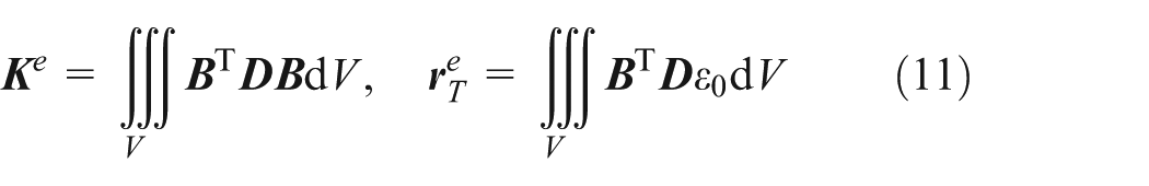
The formulation of thermal disturbance (shown in equations (11) and (12)) is defined by combining the structure’s temperature gradient with the flexible characteristics. This means that how much the budget for the payload performance will be disturbed by the thermal environment can be calculated with a qualitative analysis.
The thermal quasi-static/dynamic deformations of the large-scale flexible appendages can lead to the attitude motions of a satellite. Through the coupled equations, the satellite’s flexible characteristics including the changes of the attitude and deformations of the appendages can be analyzed.
The results of the presented numerical example show that the thermal response consists of the quasi-static deformations composed of small dynamic deformations for a simple satellite with a large flexible solar panel.
Footnotes
Academic Editor: Yan Jin
Declaration of conflicting interests
The authors declare that there is no conflict of interest.
Funding
This work was financially supported by the National Natural Science Foundation of China (Nos 11302244 and 11272334).