
Abstract
The kiln car is widely used as a kind of transport equipment in the current ceramic industry, and it is heated to the firing temperature and cooled down to the ambient temperature with products in the tunnel kiln. And the burning of the ceramics requires a lot of energy, and the efficiency is relatively low within 30% or even less. In addition, the mass ratio between car and ware can be more than 50%. So the energy loss of car also occupies a great part in total energy consumption. In this work, a mathematical model will be created to describe the temperature distribution inside the kiln car while it travels through the tunnel kiln. All the used parameters are from real ceramic industry. The operative process is assumed as a countercurrent heat exchanger. Both the convection and radiation are considered as boundary condition in the model. Furthermore, the thermal results of car and the specific energy consumption of car in the standard case will be demonstrated. Finally, the influences of different thermal physical parameters on the energy consumption of car will be investigated, and the possible optimization measures of car are proposed through comparing the different specific energy losses.
Keywords
Introduction
Energy saving is always a hotpoint. Due to the energy crisis, the energy price is quite high. In addition, the two important requirements for customer are high quality and low cost. Moreover, the emission of the combustion process also has to be treated, which constitutes the cost. Therefore, more and more industries are interested in energy consumption and how to reduce the cost during the production process. 1
While the green products are being transported through the tunnel kiln, the energy from the fuel and the combustion gas will be used for heating and firing the products. But the transport equipment is also heated at the same time, and it is the pure energy waste that unfortunately cannot be totally avoided. Obviously, the energy consumption of the products and kiln car is an important topic for current research. Unfortunately, there are still few investigations for the energy consumption of the kiln car, and it is difficult to perform the experiment in the real tunnel kiln. Therefore, the investigations about simulation of the tunnel kiln become more and more important. In 1987, Xuanhui 2 presented a two-dimensional (2D) transient heat transfer model for the tunnel kiln car. He derived the 2D Fourier heat conduction differential equation using the alternating direction implicit (ADI) method, and the kiln car which is made of different materials in different layers is considered. In 1994, Qin and Liyuan 3 created a mathematical model for a kiln car. The temperature profile was assumed to be linear, and the Fourier heat conduction law was derived from ordinary differential equations. But it still seems that we need to develop a new model to describe the temperature profile again because the previous simulated method always costs time and the result seems to be coarse. In this work, the explicit method will be used to solve the partial differential equation (PDE) in MATLAB. Both the time-consuming and energy consumption problems are solved. Furthermore, the parameters that influence the kiln car energy consumption will also be investigated. The following points show the main targets of this work:
Create a mathematical model to simulate the change in temperature profile inside the kiln car during the whole operative process;
The convection and radiation are considered everywhere including the cooling zone;
The specific energy consumption of the kiln car is calculated;
Change the parameters of car and analyze their influence on the specific energy loss.
Mathematical model
Convective heat transfer analysis
The Archimedes number is used to describe the motion of the fluid due to the density differences. If Ar < 0.2, the force convection dominates; if Ar > 10, the natural convection dominates 4

In this work, the force convection dominates the heat convection so that the Nusselt function of force convection that flows over the infinite flat plate should be applied 4


According to the above functions, the convective heat transfer coefficient (HTC) (h) can be calculated.
Radiation analysis
Gas component emissivity
Based on the general curve shapes in Hottel’s charts, an approximate exponential function is derived to calculate the emitting gas (H2O and CO2) emissivity in combustion gas. Equation (4) represents the relation between the species emissivity and gas temperature
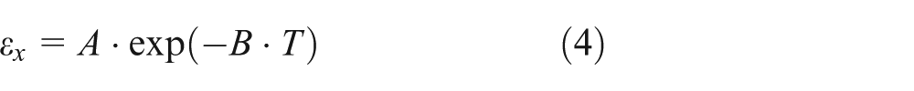
A and B are the functions of beam length and the partial pressure, respectively. The details are shown in Table 1. 5
Parameter calculation for gas species.

After all the above calculations, the emissivities of gas components are fixed and there is an approximate equation (equation (5)) that summarizes the emissivity of all species 6

Car emissivity
The general curves of solid emissivity and the temperature are shown in Figure 1.

Mean emissivity of some ceramics. 7
The kiln car is made of some refractories, such as the materials shown in the figure. Most curves in the figure are continuous and smooth profiles. It is difficult to derive equations that are used to define those curves, and also on account of silicon carbide (SiC) material which is seldom used in the construction of kiln car, according to the summary of the figure and for our convenient calculation, the car emissivity is assumed to be a linear curve that is located between the curves of fireclay and magnesite (red curve in Figure 1)

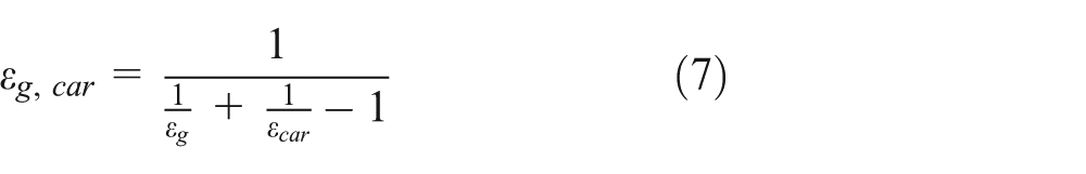
Total radiation
There are only two main media, gas and car, that account for the most part of radiation. The gas radiation is a discontinuous process that has a specific wavelength interval. Instead of a surface phenomenon, the gas radiation proceeds in the volume. So the whole system can be assumed to be a network that consists of two diffusion reflective gray surfaces (gas and car). Here, Kirchhoff’s thermal radiation law, that the emissivity is equal to absorptivity in thermal equilibrium, is applied. Then, the total gas emissivity equation can be obtained 4
Combustion gas
Because of the changing gas temperature inside the tunnel during the whole process, the other properties of gas would be influenced. This will lead to a change in HTC.
The temperature-dependent air properties can be approximated by the following equations with an error smaller than 3%


The exponent indices for combustion air are compiled in Table 2. The standard temperature of combustion gas is T 0 = 273 K, and the mean temperature of gas is T = (Tg + T car,X = 1)/2. (T car,X = 1 is the surface temperature of the car.)
Thermophysical material properties of air. 8

Numerical method
The finite difference method (FDM) is one of the numerical methods used to solve the PDE. Here, the Taylor series expansion method is implemented to discretize both the time and space domains of the one-dimensional (1D) Fourier differential equation. According to the explicit scheme, the central and boundary region discretized equations are shown below: 5
Central discretized

Boundary discretized

Energy loss
In general, it is the most important part in this work; only the energy loss is known and other improvements of the model can be taken to save the energy.
The specific energy loss of kiln car can be calculated as follows

with
Finally, the specific energy loss of kiln car is about 0.4039 MJ/kg.
Result and analysis
Simulation parameters and process
In this work, the total length of tunnel kiln is 160 m, which includes 50 m of preheating zone, 30 m of firing zone, and 80 m of cooling zone. There are 20 cars traveling through the tunnel kiln. Because the operation of kiln cars is a continuous process, kiln cars are treated as sequential layers. Meanwhile, they move at constant slow speed in the whole tunnel kiln while products which are loaded on the car should be adequately heated up. Instead of the length of kiln car, here the total length of tunnel kiln is considered during our simulation. Figure 2 shows us a general section of tunnel kiln.

General section of tunnel kiln.
A standard case will be primarily investigated in this section. All the parameters used in the standard case are typical values in real industry. The details are shown in Table 3.
Parameters of calculation.

The firing gas temperature is measured from real industry (Figure 3).

The firing curve.
The details of the simulation process are drawn in a flowchart in Figure 4. The time and space steps are of great importance during the programming. If the nodes increase, then our calculation will be more precise, but it costs longer time to finish the simulation. But in order to make sure our calculation is precise, the adaptive time and space node quantities should be chosen.

The flowchart of the simulation process.
Simulation results and analysis
Heat transfer coefficient
Based on the variable properties of combustion gas, Reynolds number and Prandtl number change all the time in the tunnel kiln. These phenomena result in the change in convective HTC in the whole tunnel kiln. As Figure 5 shows, HTC varies in a small range for the reason that the mass flow rate of gas is small. Corresponding with the gas temperature curve, HTC has both the same increase and decrease tendencies while the calculation of HTC is related to the gas temperature.
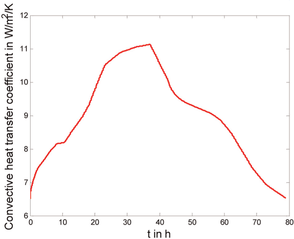
Convective HTC in the standard case.
The thermal analysis of kiln car
x = 0 m represents the bottom of the kiln car; on the contrary, x = 0.45 m is the surface of the car. As can be seen from Figure 6, because of the strong heat exchange on the surface of the car, the temperature of nodes that approach the surface will increase more quickly than that of the bottom nodes. By contrast, the temperature of nodes that approach the bottom will not be so greatly influenced because the conductivity of car is quite small. And then in the cooling zone, the temperature of the car begins to decrease, and the bottom nodes also have the same lag tendency as before. And the mean outlet car temperature is about 634 K.
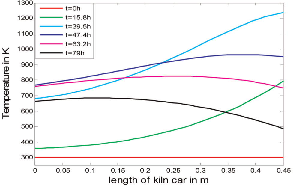
Temperature profile inside the kiln car.
Figure 7 depicts that the surface temperature profile is very close to the gas temperature profile, while the heat transfer on the surface is quite strong. After about 38 h, the car reaches the highest temperature (about 1400 K), and then it will enter the cooling zone and through a rapid cooling stage from 1400 to 900 K. This fast cooling stage will avoid oxidation of the product and make sure that the product has the vanish, half-transparence and white surfaces. 8

Axial temperature profile of the kiln car.
Axial heat flux
In Figure 8, it can be seen that the radiation dominates the total heat transfer mechanism in the whole process before the cooling zone, and the reason is that the gas temperature is always high during the operative time. The minimum gas temperature is over 200 °C, while the radiation heat flux function is an exponential equation of the gas temperature with power 4, so it will dominate the total heat flux. But in the cooling zone, the radiative heat flux will disappear while the cooling gas is without the emitting gas, and then there is no doubt that the convection will dominate the total heat transfer in the cooling zone.

Surface heat flux of the kiln car in the standard case.
Parameter variation
On account of the standard case, some parameters as variables will be changed one by one to discuss their influence on the specific energy consumption of car in this section. Only one variable is investigated in every case, and others will be kept as the standard case.
Thermal conductivity
Because in real industry the kiln car is often made of two different materials, constructive and insulated materials, and the conductivity of insulated material is relatively smaller than that of the constructive one, here the conductivity of car from 0.01 to 2 is investigated. Figure 9 shows that the energy loss of the car becomes larger with increasing conductivity. Burton S60T, whose conductivity is about 1.52, is widely used as the constructive material inside the kiln car, and Burco 13/25 and 14/25, whose conductivities are approximately 0.55 and 0.68, respectively, are used as insulated materials in Germany. The conductivity is a parameter that is used to evaluate the conductive capacity. The higher the conductivity, the smaller the conductive resistance. The heat will more rapidly transfer from surface to bottom. In general, the energy loss will be more with the increase in conductivity.

Energy loss change profile due to changed conductivity.
Density
Figure 10 shows that the energy loss of the car decreases with the increase in the density of car. Because in real industry the density of car cannot be a large value of more than 2000, here the density range from 200 to 2000 is considered. While the bigger the solid density is, the more molecular in a unit volume is, so it may lead to the higher conductive resistance. Therefore, in general, the conductivity will decrease due to the increase in solid density and also the thermal diffusivity of car will reduce due to increasing density so that the heat transfer effect inside the car will be worse. As a result of that, the energy loss from gas to car will be smaller. After 1400, the energy can be assumed as constant. Here, Burco 13/25 and 14/25, whose densities are about 1300 and 1400 kg/m3, respectively, seem to be a better material than that used in the kiln car.
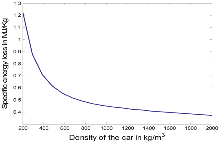
Energy loss change profile due to changed density.
Dimension
Because only one dimension (vertical direction) is considered in our model, here the height of car is set up as the variable. The energy loss increases with increasing car height, especially in the range from 0.3 to 0.5, and there is a sharp gradient where the energy loss rapidly increases (Figure 11). After 1 m, the energy loss is steadily constant at about 309 MJ/m2. The reason for the increase in energy loss is that the lower the car, the larger the Fo. Therefore, the heat will transfer faster from surface to bottom by conduction. It means the temperature inside the car will increase more rapidly in the higher car and the temperature difference between the gas and the car will be smaller so that the energy loss is saved.

Energy loss change profile due to changed car height.
But because of the increase in the height of car, the unit mass of car will be more larger and the specific energy loss over car mass will oppositely decrease due to the greater expansion of dimension.
Conclusion
The FDM can be successfully implemented to discretize the Fourier conduction equation with the natural boundary condition. The simulation process is steady and easily checked.
Figure 12 is the experiment result from a company named “FORGESTAL S.L.” Corresponding to different heights in our simulation, the kiln car which is used in the experiment is made of different layers. The highest gas temperature is approximately 1400 K. The total processing time is 71 h. And the figure also shows the further cooling stage by air after the cars leave the tunnel kiln. The only different condition is that the setting which is loaded on the car is considered in the experiment.

Temperature profiles of car and products from experiment. 9
As can be seen from the figure, the general curve of our model (Figure 7) approaches the real industry. The tunnel kiln was not developed so fast due to the limitation of experiment and construction cost. The result profiles match company temperature well and can be used for analysis without performing the experiment in a large-dimension tunnel kiln. In addition, it is rarely that computational fluid dynamics (CFD) code is used to simulate real tunnel kiln in three-dimensional (3D) model without simplification because of time consumption. The main target of this work is to propose a new numerical method which can be implemented to investigate the general effects of parameters on the energy consumption of kiln car. Our simplified model can be used to solve a specific problem without creating a complex model in CFD. Some conclusions are listed:
This discretized model can predict both the axial and radial temperature profiles inside the kiln car.
The energy consumption of kiln car during the whole process is small.
The temperature difference between the car surface and the gas is small, which is about 50 K.
The radiation dominates the whole firing process in the heat transfer mechanism.
The conductivity of car, that plays an important part in saving energy, should be reduced to as small as possible in real industry in order to reduce the energy consumption of kiln car. In industry, it would be suggested to use more refractory and insulation material while constructing kiln cars.
It is reasonable to keep the car density larger than 1400 so that it can save more energy. More details on heavy density material should be concentrated instead of light density material.
The height of car should be as high as possible but in reasonable height so as to reduce the energy loss of kiln car.
The combustion gas temperature that is used in firing should not be too high, and it will save more energy rather than higher gas temperature. One possible measure is to control the fuel injection amount which is used in combustion reaction.
The CO2 and H2O could be considered for injecting into the cooling zone so that radiation heat transfer will affect this zone. And kiln cars will release more energy back to the gas that will result in saving energy.
Footnotes
Academic Editor: Hyung Hee Cho
Declaration of conflicting interests
The authors declare that there is no conflict of interest.
Funding
This research received no specific grant from any funding agency in the public, commercial, or not-for-profit sectors.