
Abstract
The use of sanitary water is a main aspect of comfort and healthiness within a house or a public environment as gyms or beauty farms. At the same time, water waste should be limited to a minimum in order to preserve both water and the energy required to warm it. To obtain these results, it is necessary to rule quickly and in a precise way the temperature. It is also necessary to check the presence of possible contemporary flow requested by different users in order to optimize distribution in the house network. This work describes a mechatronic water mixer that was developed to ensure fast and precise control of flow and temperature of delivered water. The flow control is based on modulating digital valves driven in pulse code modulation and on a microcontroller board. The electronic unit is designed to interface with a domotic network for remote control and total consumption monitoring and optimization.
Introduction
Water and energy consumption should be consistently limited in order to reduce the environmental impact of human activities. To reach this goal, it is important to optimize the use of warm water for sanitary use in domestic environment as well as in hospitals, sport plants, and wellness centers. 1 A suitable way is the use of solar thermal plants to produce and store warm water during sunny hours. 2 It must be kept in mind that in order to maximize the efficiency of solar thermal storage systems and to prevent legionella, it is mandatory to store warm water at high temperature, at least 60 °C. 3 The former involves the need of mixing warm water with cold one to reduce its temperature to values low enough to prevent scalds. Moreover, attention must be paid to prevent very warm water to flow outside a faucet for a long time in order again to avoid scalds that could be very dangerous especially for children or elders.4,5
At the same time, the field of water distribution network can be an important area for the application of home automation system in order to increase safety in public and domestic environments and to monitor, meter, and organize water distribution in large structures. 6
In up-to-date water distribution plants, the regulation of sanitary water temperature is carried out by thermostatic systems based on the action of a thermo-sensitive wax that provides a mechanical feedback for temperature. The blockage of water supply in the cases of excessive high or low temperature is exerted by a thermo-sensitive wax device too, which has very short response time. A good description of this system together with a detailed model is provided by Costa et al. 7
This kind of device, however, is not suitable for the interaction with a home automation network as it is operated manually and it does not include any kind of flow measurement.
This work describes a solution that was developed by the authors to construct an automated thermostatic mixer in which flow rate and temperature are remotely ruled by a control board and water consumption data are acquired and transmitted. The device can hence become an intelligent agent of an interconnected water control system.
The nonlinearity of the wax sensitive device may lead to low precision in the regulation of the water temperature. For this reason, a closed-loop control system with the simultaneous control of flow rate and temperature was decided to be used. In order to obtain a fast response of the system, a mechanical solution in which hot and cold water supply flow are governed by a set of digital actuators controlled in pulse code modulation (PCM) was used. A similar solution can be found in Laamanen et al. 8 where a 7-bit valve arrangement was implemented to control the amount of water used for binding dust.
This article discusses the system layout with its control algorithms and shows some results obtained in experimental tests. A simplified mathematical model of the system is provided in order to analyze the control of the system.
General system architecture
The mechatronic mixer is composed by a mechanical system to regulate the flow rate and a sensor assembly composed by flow and temperature transducers disposed downstream of the outlet port. Flow and temperature control algorithm and the interface with the domotic network of the building are provided by an Arduino board. Finally, the local input for controlling the flow and temperature is provided by a dedicated interface panel (Figure 1).

System layout.
The user can set a reference value for temperature and flow rate of the water delivered by the mixer. The output temperature can be ruled in a range between 28 °C and 44 °C by steps of 1 °C, while the flow rate can be adjusted on three different values, namely, “low,”“medium,” and “high,” corresponding respectively to 10, 20, and 30 L/min. These values are selected according to the typical flow rate of large shower and bath faucets. The basic tasks that can be performed by the system are temperature and flow rate regulation, cut-off in the case of excessive temperature and measurement of the provided water. Total and partial consumption can be shown on the display and transmitted to the domotic network.
Mechanical layout of the mixer
The mechanical mixer is designed in order to operate according to PCM technique. It is composed by a manifold with two inlet pipes, for warm and cold water, respectively, and by an outlet pipe for mixed water (Figure 2).

Manifold layout.
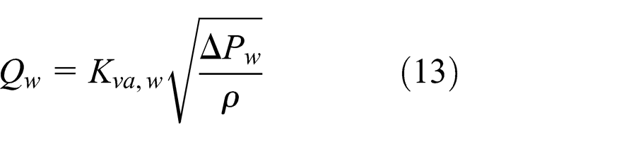
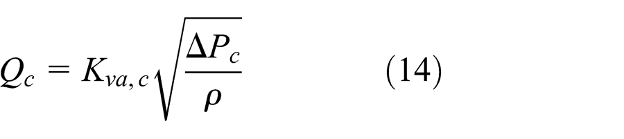
Each inlet pipe is connected to the outlet pipe by a set of five digital two-way two-position valves. Each ith valve is characterized by a flow rate coefficient Kv which doubles that of the (i−1)th valve.
According to this assembly, the total flow coefficient of the port linking warm or cold water pipe with the mixed one is the sum of the flow coefficient of the open valves, defined as
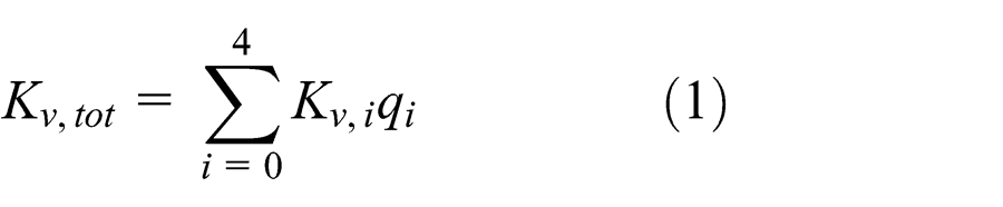
where
Considering that
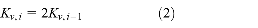
it is immediate to realize that the flow coefficient of the ith valve can be defined as a function of the flow coefficient of valve 0 as

And then the total flow coefficient is
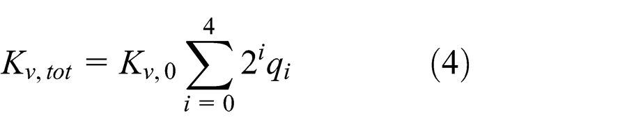
and it can assume 32 discrete values ranging from 0 to 31Kv,00.
The mixer regulates the temperature and the total flow rate in closed loop, thanks to the temperature and flow rate sensors placed downstream of the mixer. In Sciacovelli et al., 9 the temperature distribution of the outlet flow was analyzed.
This arrangement potentially provides a fast actuation to regulate the flow rate across the warm and cold water pipe, upon which rate and temperature of the outlet flow depend.
In order to obtain a short response time, the manifold was constructed considering the use of plugs actuated by solenoids to open and close the orifices that allow flow between the pipes. The selected assembly of poppet and solenoid has a response time of 0.1 s, and this involves that the response time of the whole valves assembly is 0.1 s too.
Control algorithm
The control algorithm was designed to simultaneously regulate temperature and flow rate. Two closed-loop controllers that operate contemporarily on the warm and cold valve bench compose it.
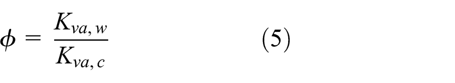
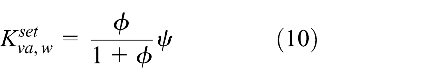
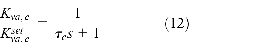
The control processes the reference and actual values of temperature and flow rate in order to compute the actuation values Kva, w and Kva, c for the warm and cold side valve assembly.
In order to set the two variables, two proportional–integral–derivative (PID) controllers with a feed-forward branch were designed, as shown in Figure 3.

Block schematics of the control algorithm.
The feed-forward values are set considering two standard values for cold and warm water temperature, which were chosen to be, respectively, 20 °C and 60 °C. The PID controllers compute the setting values for variables
and

Feed-forward values are computed considering equal and nominal upstream pressure at the cold and warm valve sides, that is, considering that at equal flow coefficient should they correspond equal, nominal, flow rate values.
The Kv values are considered dimensionless, and they range from 0 to 31, coherent with the discretization range defined in the former section.
In nominal pressure conditions, the flow rate corresponding to fully open side is 30 L/min, and this value is considered to compute the feed-forward value for flow rate feedback control.
The feed-forward values

and

Finally, the actuation values

and
System model
A model of the plant was developed in order to find suitable combinations for the gains of the PID controllers.
The nonlinear model is based on the following equations


In order to consider the thermal transient of the water, some tests were carried out to measure the time constant to model it as a first-order system, and it was evaluated as 0.2 s.
The flow rate and temperature sensors were modeled as first-order systems too, their time constants were analyzed in order to define their requirements, and the same was considered for the actuators of the digital valves.
The nonlinear model was implemented in the Simulink environment.
Prototype construction
A prototype was built in order to carry out experimental tests. The manifold was constructed according to the drawings of Figure 4.

Mechanical construction of the manifold.
In the left part of the figure, a complete system layout is shown. The inlet pipes A and B can be seen as well as the two-valve benches C and D. In the left part of the figure, a section of the manifold is shown, where the water mixing pipe W and the valve that places the inlet pipes in communication with the outlet pipe can be seen.
Inlet pipe B is connected to a chamber F via the pipe E. The chamber F is connected with the mixing chamber by a line G. A poppet H, actuated by a solenoid L, can open or close water admission to line G and then it opens and closes the communication between pipes B and W. The poppet H is kept in its rest position by a spring which is not represented in the drawing. The normal position of the arrangement is such that the valve is closed in the absence of command voltage. The stiffness of the spring is calibrated to ensure perfect closure for pressure up to 8 bar. Finally, the admission port to line G includes a nozzle with a calibrated hole that defines the flow coefficient across the valve.
Five different kinds of nozzles were built, each one with different size of the calibrated holes designed in order to obtain the desired ratio in the flow coefficients. The calibrated holes have the following diameters: 1, 1.41, 2, 2.82, and 4 mm.
An integrated temperature and flow rate sensor was selected to control the system. The flow rate measurement is based on ultrasound technology, and its response time is 0.35 s. Temperature measurement is based on a thermocouple, and its response time is 0.1 s.
The control algorithm was implemented on an Arduino board interfaced with the valves by a power board including 10 opto-isolators that drive the solenoids. Control input is provided by a user interface that allows the selection of flow rate and temperature and the visualization of the water consumption. In Figure 5, the final prototype can be seen.

Manifold prototype.
User interface
Figure 6 shows a picture of the user interface. It is composed by a three lines display upon which the controls are placed.

User interface prototype.
In the upper left part, two buttons allow increasing and decreasing of temperature set, while in the upper right part, the buttons “litri” and “reset” allow reading of the water consumption since last reset and resetting the counter.
In the middle level, the on/off command is placed together with the start/stop one.
Finally, in the bottom line, three buttons allow the selection of the desired flow rate considering three discrete values (small, medium, large).
The interface is intended to be installed within the shower or bath and to be connected by a wireless link with the control board of the mixer.
Test setup
To carry out characterization tests, a setup in which warm and cold water can be supplied at constant temperature and pressure was developed. Variable flow resistances were introduced along the supply lines in order to simulate the effect of a reduction in supply flow due, for instance, to the insertion of another user on the same water distribution network (Figure 7).

Test bench layout.
Warm water supply temperature was set to 60 °C and cold water temperature to 20 °C.
In true operating conditions, actual supply temperatures are probably different from the expected values Tw, th and Tc, th used in the feed-forward branches of the controller. To consider this aspect, the reference values were set to 65 °C and 25 °C, respectively. Other tests were carried out setting 55 °C and 15 °C, respectively.
The measured data include pressures PW and PC along the supply lines and output flow rate Q and temperature T.
Test results
The following graphs show some results obtained during the tests. Each test was carried out setting the reference values for flow rate and temperature and evaluating the performance of the system at ensuring their regulation when a disturbance is applied. This disturbance is achieved by acting on the flow regulation valves to restrict the supply lines.
Figure 8(a)–(e) shows results obtained in four different types of tests:
Flow rate limitation along warm water supply line;
Flow rate limitation along cold water supply line;
Step variation of +3 °C of reference temperature;
Step variation of −3 °C of reference temperature;
Step variation of −10 L/min of reference flow rate.

Results of experimental tests: (a) restriction of cold water supply line, (b) restriction of warm water supply line, (c) increasing reference temperature of 3 °C, (d) decreasing reference temperature of 3 °C, and (e) decreasing reference flow rate by 10 L/min.
In each figure, the behavior of temperature and flow rate together with the disturbance or reference change versus which the response of the servosystem is analyzed is reported.
The results show that under all the considered circumstances, the system reacts promptly, and it reaches new steady state conditions in a time included between 5 and 10 s, stabilizing the system at the reference values.
Finally, tests were carried out to measure the response time to an abrupt increase of temperature over a threshold level set at 55 °C. The control board was programmed to close all the valves whenever this fact happens, in order to stop the water flow rate and to prevent damages or burns. Cold water flow rate was abruptly interrupted by acting on the resistance on flow rate supply pressure, and the time elapsed between the overcoming of the threshold and the end of the water outlet was measured.
As the response time of the flow rate sensor is larger than the response time to be measured, the test rig was modified to include a downstream pressure sensor and a downstream fluid resistance. The time to stop mixed water supply was hence measured as the time delay between temperature overshoot and fall to zero of downstream pressure.
The average measured time was 0.55 s, which is largely shorter than the maximum delay of 3 s allowed by the standard NF 077 Rev. 15. 10
The experimental results show that the behavior of the system is generally satisfactory as regards temperature regulation: under all the considered test conditions, the reference temperature is recovered quickly and the perturbation lasts less than 5 s. Only in case (c) in which the reference temperature is increased by 3 °C, the water temperature after reaching the reference +0.5 °C within 5 s from perturbation shows some more oscillations in the next 15 s. These oscillations are within the reference +1 °C to −0.5 °C. Similarly, the temperature in case (d) where its reference value is reduced by 3 °C reaches the ±1 °C error range within 5 s from command, but it requires 15 s for a total stabilization.
As regards flow rate regulation, it can be pointed out that its reference value is recovered in a time included between 5 and 10 s in all the tests. Here again, the worst performance is shown when the reference value is changed by the user.
These regulation results show that the system respects the requirements defined by the French standard NF 077 Rev. 15, which transposes the corresponding European Standard, and then it is possible to conclude that the performance is satisfactory.
Conclusion
This article proposes a new architecture for the construction of thermostatic water mixers that use a mechatronic approach to ensure temperature and flow rate regulation.
The main advantages of the proposed solution are the promptness of the response in the case of temperature overcoming of a safety threshold, which is a major requirement to prevent burns. At the same time, the system can be interfaced with a domotic network for building automation. This can be important to optimize water distribution for the requirement of large number of users at the same time, as it can easily happen in sport clubs or similar facilities.
Footnotes
Appendix 1
Academic Editor: Zhaowei Zhong
Declaration of conflicting interests
The authors declare that there is no conflict of interest regarding the publication of this article.
Funding
The authors wish to thank Regione Piemonte and Polo di Innovazione del Lago Maggiore for their financial support within the M10Flow project (Misura I.1.3 “Poli di innovazione–II Programma”).