
Abstract
Digital hydraulics offers advantages over traditional proportional valves but lacks high flow rate performance. This study proposes a solution based on operated on/off valves. The proposed system achieved a flow rate of nearly 350 LPM at nominal operating pressure with a roughly 25 ms fast response time. A novel dual flow solution is also presented and analyzed. These breakthroughs demonstrate the innovative feasibility of implementing pilot-operated, stroke-limited on/off valves in digital hydraulics. The results show that more possible discrete flow rates were achievable using the dual discrete flow method. In conclusion, the grouping of these valves and digital control approach enhances fluid power systems resolution, opening new possibilities for wider adoption, and improved performance in digital hydraulic systems.
Introduction
Binary-coded configuration for digital hydraulic system
Digital Flow Control Units (DFCUs), a method of managing fluid power systems, operates in parallel-connected valves utilizing binary principles much like Pulse Code Modulation (PCM) in signal processing, where analog signals are converted into digital ones. Within the realm of hydraulics, this binary-coded system operates based on the “on” and “off” states of the valves. These combined binary-controlled valves can realize a wide range of accurate flow rates with compact size, in contrary to other coding mechanisms, such as PNM or Fibonacci coding. The core advantage of digital hydraulics lies in their fault tolerance, exactness, robustness, and, most importantly, standardization, paving the way for significant advancements in fluid power technology. 1
In response to rising energy costs, stringent emissions standards, and the need for greater productivity, digital hydraulic systems have been developed, initially as an alternative to high precision proportional valves, and subsequently as an alternative to conventional displacement-controlled systems.2,3
An ideal PCM system would consists of several parallel-connected on/off valves whose flow capacities are in the ratios of
Proportional valves market analysis and digital hydraulics research for high performance two-way valves
High performance valve (such as pilot operated valves) units find wide-ranging applications across various sectors, characterized by rigorous hydraulic demands. In the field of mining, they are integral to hydraulic supports within coal mining operations. 4 They play a pivotal role in high-pressure systems like hydraulic forging presses5,6 and offshore drilling rigs. 7 Their robust functionality extends to large drilling machines used for tunnel excavation. In mobile machinery, these valves exhibit significant utility in hoist control systems of large-scale trucks, exemplified by models like the CAT 797F.
In a comparative market analysis, Parker TDA 2/2 one-way proportional three-stage throttle slip-in cartridge valves (size NG25) 8 yield a flow rate of 352 LPM at a modest 5 bar, responding within 25 ms at a pilot pressure of 50 bar. Rexroth 2WFC, a 2/2 pilot-operated proportional cartridge valve, 9 offers 330 LPM for the NG25 size, exhibiting a linear-progressive structure with non-linear flow stroke performance, and a response time of approximately 50 ms when operating at 100 bar at ports A, B. Lastly, Vickers’ CVU-**-EFP1 two-stage Valvistor proportional throttle valve (NG25) 10 achieves a flow rate of 320 LPM at 5 bar, with a response time of 60 ms when operating at 100 bar at ports A, B, and X. This analysis indicates that the valves currently available on the market necessitate high pilot pressures to attain such rapid response times. The high control pressures in valves for high fluid flow rates are primarily due to increased hydrodynamic forces on the moving components (poppet or plunger) as flow rate rises. Hence, the control force must exceed all combining forces, necessitating higher pilot pressures to achieve rapid response times. 11
Additionally, the requirement intensifies for servo-controlled proportional valves. Despite advancements with VCD technology in the new (year 2021) two-way TFP Parker valve series, 12 these valves offer higher flow at lower pressure drops but require a minimum pilot pressure of 140 bar to achieve fast response time of 9 ms (NG25). 13
Looking at the academia, at Aalto University integrated fluid power research, 14 they utilized a main-stage 2/2 bi-directional two-stage, slip-in cartridge valve, piloted by two 2/2 on/off Bucher Hydraulics WS22 solenoid-operated valves. This assembly confirmed a response time of 27 ms at 200 LPM, under an 80-bar pressure difference. Another study by Taiyuan University of Technology in 2022 4 introduces a high-capacity, quick-response directional proportional valve for large water hydraulic systems. This valve, employing a three-stage structure with high-speed 2/2 solenoid valves as the pilot stage, achieves a 20–30 ms response time and 1100 LPM flow rate at a 10 bar pressure differential. High-speed 2/2 on/off valves have previously been employed in the pilot stage of pilot-operated valves, yielding several advantages such as improved efficiency, digitalization, and precise control. These benefits, thoroughly explored and discussed in a recent review article. 15 Historically, digital hydraulic applications have been constrained to limited flow rates, with the highest flow rate DFCU achieving 115 LPM at a pressure difference of 5 bar. 16
Three key innovations in the proposed DFCU
This article proposes a DFCU with six valves, as this number could be expected to provide resolution comparable to servo-controlled proportional valves. 17 The current research aims to engineer a DFCU that matches the performance of a 2/2 proportional valve, targeting a specification of approximately 350 LPM at 5 bar with a response time of around 25 ms. By employing a PCM configuration, the proposed DFCU is expected to surpass all previously assembled DFCUs. Due to this unique configuration, the DFCU not only has a higher flow capacity but also offers better resolution.
To distribute the 350 LPM flow discretely among the parallel connected valves in a binary coded DFCU, two methods can be used: limiting the valve stroke or attaching an orifice to it. The stroke limiter technique, chosen for its better dynamic response, 18 was tested on pilot-operated valves, was chosen for testing on pilot-operated valves. Moreover, Gao et al. 19 experimentally verified that a larger maximum stroke of the main valve reduces its response time. This marks the introduction of the first DFCU with the stroke limiter technique according to the best of authors’ knowledge.
Additionally, the study innovatively utilizes a dual function of the pilot operated valve ensemble, enabling two distinct flow rates from the same pilot operated valve unit, thereby enhancing resolution and compactness, which are the main advantages of PCM coding, as detailed subsequently.
As a secondary contribution, the study presents a novel algorithm for calculating flow disturbances caused by valve timing discrepancies during switching, beyond merely assessing the deviation of actual flow from the desired flow. This approach is essential for effectively addressing flow disturbances that arise in PCM configurations.
Study limitations
The proposed DFCU with binary-coded series offers
PCM control manages valve operations to regulate flow rate precisely. However, timing discrepancies can cause flow fluctuations (Crests or Troughs) during valves switching, 20 particularly when at least one valve is opening while another is closing. This study identified 2702 (Instructions on how to calculate these 2702 incidents are outlined here 21 ) such incidents for a typical DFCU (n = 6) with PCM configuration, with the intensity of flow deviations varying according to valve sizes and operating conditions.
This study will remarkably reveal that the use of externally pilot-operated valves enables the formation of fluctuations under different switching scenarios compared to conventional aforementioned incidents. Therefore, to diminish these fluctuations along with other fluctuations incidents that will be presented it is crucial to: (i) accurately model these pressure peaks and (ii) implement an optimization algorithm to optimize valve timing. 22 While these objectives are beyond the scope of this article, they are mentioned to provide a comprehensive context for the reader. The primary focus of this study is to present and evaluate the overall configuration and response time of the newly proposed DFCU, highlighting its novel features.
Moreover, data from manufacturers and published experimental studies by other researchers have been preferred over detailed 3D modeling of the valve. This approach is adopted to focus on the main unit outcomes and assessments, ensuring that the findings are applicable to various valve manufacturers beyond the one specifically addressed in this study.
Mathematical modeling
System configuration
Designed DFCU binary valve system
To achieve the desired DFCU with 350 LPM at 5 bar (nearly matches the performance of NG25 size two-way valves) through binary coding, the system configuration encompasses six output flow valves, divided into three pilot-operated and three direct-operated valves. The enhanced Bucher direct operated valve type WS22GD-**, not on the market but studied in detail through, 16 is employed. That valve uses Bucher hydraulic cavity Type DH, compatible with pilot-operated valves WS22GNH-**Size 10, per ISO 7789. Two of these valves namely DV1 and DV2, are paired with unique orifices, limiting their flow to 8 LPM (2.8 mm orifice) and 15 LPM (4 mm orifice), while the third valve, DV3, offers 37 LPM at 5 bar with no orifice connected. The pilot-operated valves are Rexroth stroke-limited, two-way cartridge valves NG16. 23 The pilot-operated, stroke-limited valves, POV4, POV5 and POV6, are adjusted to have flow capacities of 75 LPM (3.1 mm stroke), 104 LPM (4.3 mm stroke), and 125 LPM (5.2 mm stroke), respectively.
While Six Bucher pilot valves of the same type as the direct ones, namely In_PV4, Out_PV4, In_PV5, Out_PV5, In_PV6, and Out_PV6, without any orifices (37 LPM) are used in pairs to operate the three Rexroth pilot-operated valves. Kindly refer to Figure 1 for a visual representation of the system.

Digital flow control unit layout, DFCU (n = 6 + 1) at full operating state.
Pilot-operated valves selection assessment
Given the high flow rate requirement of the DFCU, two-stage poppet valves, either externally or internally piloted are essential. Externally piloted operated valves, more suitable to bi-directional flow implementation,24,25 present an advantage. Moreover, integrating a stroke limiter for the sack of achieving discrete flow rate in internally piloted flow control valves poses challenges. 18
The matching relationship between the pilot valve and main valve is crucial for the hydraulic pilot control system in engineering machinery, the Rexroth Type LC cartridge valves, featuring a Type LFA-HWM control cover, are selected. 23 The chosen model, size NG16, has a nominal flow rate about 200 LPM at 5 bar. This valve configuration mentioned to have a response time of nearly 10 ms when recommended pilot flow is provided. The manufacturer recommends using a four or three-way spool-WE-6 valve as a pilot valve to manage the main stage. However, this study opts for two 2/2 direct acting on/off poppet valves with response times around 14 ms, serving as pilot valves. These “decoupled” valves aligned with the digital hydraulics approach. At the same time, changing the operational states of the 2/2 piloting valves allows fluid to flow bidirectionally across the pilot-operated valves. 26
Governing equations
To accurately model a PCM DFCU, integrating both (i) Steady-state and (ii) Dynamic equations is essential. Steady-state equations determine the required valves for a desired flow rate; once this is settled, the dynamic model simulates valves operation, considering response times and transient states.
Calculation of flow capacities using steady-state equations
First step, the system flow capacities can be expressed mathematically based on the given information provided by the manufactures datasheets (Table 1):
Valves flow coefficients.

The

Where

With
The pilot valves are excluded from the steady-state flow estimates as they are not involved in continuous flow supply to the output system.
It should be mentioned that only in the case of Out-PV6 valve, coupled with In-PV6 valve, will the pilot valves participate in continuous flow steady-state calculations. This scenario requires a different steady-state model, detailed in Section ”Introduced dual operation scenario.”
Dynamics of valve operation
Bucher valves (direct and pilot)
The valve is modeled following standard procedures, which include limiting the first derivative during opening and closing, along with incorporating a constant delay value. 29 Additionally, the valve was observed to have a nearly constant response time under varying, studied operating pressures, as experimentally verified in Ketonen and Linjama.16,30
Therefore, the dynamic flow rate of the valve can be expressed as follows:


Where
Rexroth valves (pilot operated)
Areas and strokes
The pilot-operated cartridge valve depicted in Figure 2 operates based on the following descriptions. The step area
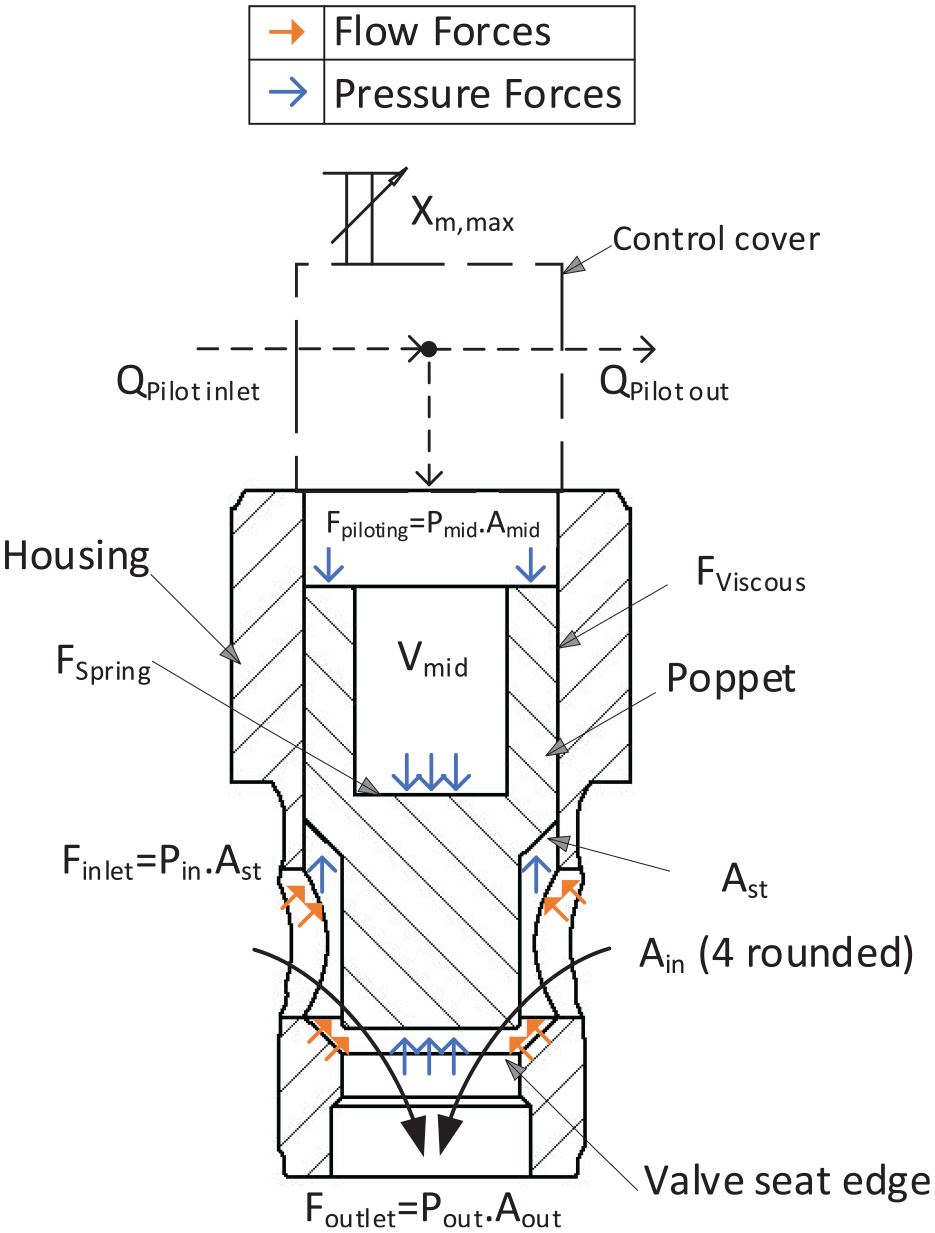
Pilot operated valve main parameters and force analysis, modified from Bosch Rexroth. 32
In order to model the pilot operated valve outlet area, plunger half angle
Spring force
A soft compression spring is positioned on the main poppet within the control chamber to guarantee the main valve remains closed when no fluid forces are present. The spring constant coefficient
The spring force should be slightly less than cracking pressure forces, the selected cracking pressure from the catalog is 2 bars. hence the pilot pressure is
Damping impact
In general, all forms of friction contribute to the damping of a system. This is because frictional forces always oppose the direction of motion. The viscous friction coefficient,
Hydrodynamic forces
Valve designers and manufacturers has been keen to prioritize minimizing pressure drops and hydrodynamic forces negative effect while ensuring stable operation. Commonly, research articles have explored the reduction of hydrodynamic forces
In the case of the addressed Rexroth valve, the areas
A rough estimate for the flow forces under extreme conditions of 125 LPM at ΔP of 5 bar across the POV6 poppet can be calculated using the formula
Governing equations
The dynamics of the Rexroth valve are modeled more detailed using the equation of motion, unlike the Bucher valve, due to several critical factors. Firstly, the Rexroth valve poppet has significantly larger inertia, which greatly influences its dynamic behavior and response time. Secondly, the complex interactions between the Rexroth valves and the Bucher pilot valves, along with the varying stroke lengths that impact flow capacities, necessitate a comprehensive dynamic model to ensure precise control and performance optimization. Thirdly, the higher flow rates of the Rexroth valves increase the intensity of flow fluctuations and their impact on the system in dynamic states, making detailed modeling essential as presented below:
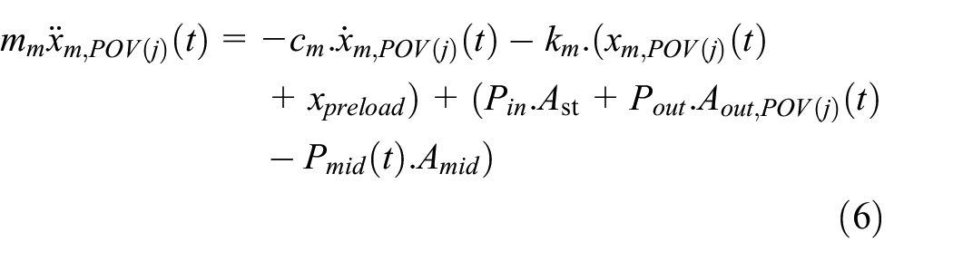
Where the main mass
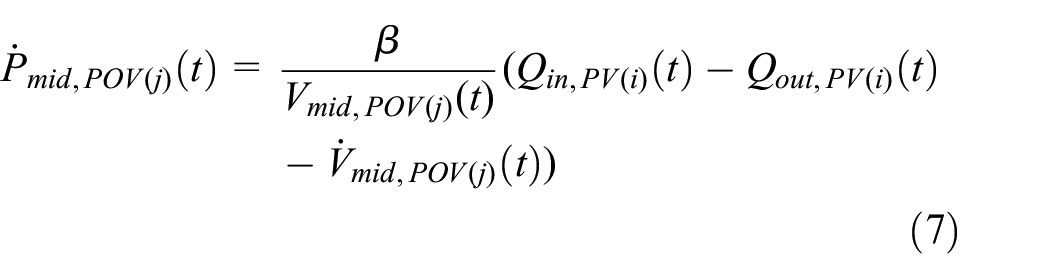
Also, mid volume when main plunger is at bottom
The mid pressure
The values of

Introduced dual operation scenario
Dual pilot valve flow management
An innovative methodology has been proposed enabling dual discrete flow rates from the same pilot-operated valve assembly, comprising two 2/2 pilot valves and a main valve. This methodology involves either opening both pilot valves for flow propagation through them (as shown in Figure 3(a)), ensuring main pilot operated valve closure, or closing the inlet side connected pilot valve while simultaneously opening the outlet side connected pilot valve, guaranteeing main pilot valve opening (Figure 3(b)).
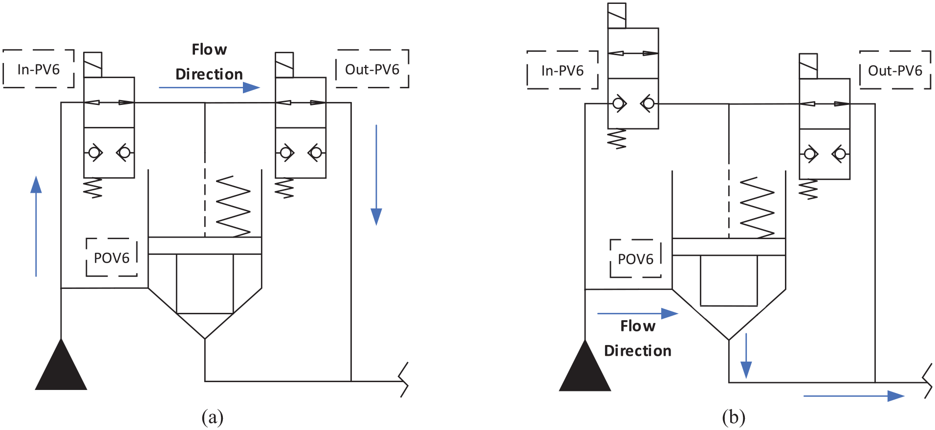
Simultaneous opening of the two 2/2 pilot valves to enable dual discrete flow, applied on POV6. (a) 26 LPM at 5 bar and (b) 125 LPM at 5 bar.
The steady-state equation for Case (b) in Figure 3 will be presented through Section “Governing equations,” However, to model Case (a), the combined flow coefficient for the two valves,

Choosing optimal dual-mode configurations in valve assemblies
This section investigates the potential of obtaining three dual discrete flows from three pilot-operated valve assemblies. Despite this innovative potential, several challenges and considerations arise. Initially, it is not feasible to derive two discrete flows from the pilot valve assembly (as shown in Figure 3) at the same time. Furthermore, when dual valve assembly outputs are linked to the main line rather than the tank, a flow surge occurs upon the controller command to open the pilot-operated valve. This surge results from the necessity to evacuate the pilot flow in the Rexroth valve pilot (mid) chamber before the valve poppet rises and allows flow to the main line.
A direct solution to aforementioned issue involves connecting the pilot valves output to the tank side. Moreover, the pilot valves were chosen based on the maximum flow rate advised by the manufacturer. As such, all pilot valves linked to the three pilot-operated valves maintain identical flow rates and employing pilot valves with lower “different” flow rates to have unique flow capacity would delay the main valve response time.
The plot diagram (Figure 4) illustrates four distinct valve configurations: DFCU (n = 6 + d), where d could be 0, 1, 2, or 3. The “Dual function” is not implemented in DFCU (n = 6), whereas it’s fully implemented in all pilot-operated valves in DFCU (n = 6 + 3). The number of discrete flow step sizes was computed by calculating the differences between successive flow values. In the standard DFCU (n = 6) is 64, this figure increases to 96, 144, and 216 for DFCU (n = 6 + 1), DFCU (n = 6 + 2), and DFCU (n = 6 + 3), respectively.

Comparative analysis of pilot valve assembly configurations.
Remarkably, the symbol “d” has been presented to denote Dual-Mode, a new change, since the digital hydraulics concept was first reintroduced nearly 20 years ago.
From the previous plot, it can be observed that the median shifts to smaller flow rates as the dual function is increasingly implemented. The data suggests that dual functions enhance precision, especially at low flow rates. This is a particularly challenging task in flow tracking for digital hydraulic systems. 44 Moreover, particularly increasing the Dual mode from DFCU (n = 6 + 2) to DFCU (n = 6 + 3) doesn’t notably enhance the step size. However, the rise in the 0–5 LPM Step Size Range compared to DFCU (n = 6 + 2) is due to the redundancy of achieving the same flow rate with different valve combinations. This could be an advantage that, when the system is well-optimized (Future research direction), helps minimize the occurrence of flow peaks in DFCUs during flow state shifting, as more flow combinations are achievable. However, it is advisable to initially study the concept in a simplified manner to fully understand and grasp the complex flow disturbances, which may be difficult to identify if multiple pairs of pilot valves are connected to the output. Based on that, DFCU (n = 6 + 1) is chosen as a compromise option.
In the dual mode cases, the controller ensures that no instance occurs where both the POV6 and the dual pilot valves (In_PV6 and Out_PV6) simultaneously receive a “1” signal. It optimizes for the smallest error, elects specific configurations, deciding on either open both pilot valves or open the pilot operated valve.
Then, the total DFCU (n = 6 + 1) flowrate is:

Where,

Dual operation limit
This section studies the conditions under which the pilot operated valve (POV6) will remain closed despite the opening of the two associated valves (In_PV6 and Out_PV6) as shown in Figure 3(a). This is achieved by equating the forces responsible for closing, represented by equation

Pilot operated valve closure analysis in case of dual scenario.
Given that the Bucher valves closing time is modeled to be nearly equal to its opening time (14ms), 16 Rexroth pilot-operated valves exhibit a distinct pattern. As shown in the upcoming results section, the closing time for pilot-operated valves is slightly quicker than the opening time. This discrepancy occurs because the closing force is greater than the opening force, a concept which is clarified in Figure 5.
Controller
Overall flow controller implementation
The valves flow rates subsystem computes the flow rate for each valve based on the input ΔP as shown in the Mathematical section. This allows the main controller to select the optimal control signal that achieves a flow rate close to the reference from a generated search space matrix which has all possible valves combinations.
The flow rate through the DFCU is calculated by summing the corresponding valve flow rates. The resulting flow rates are outputted in a vector

High level controller diagram for the DFCU.
Quantifying flow disturbances in DFCUs
Types of expected flow disturbances
Three types of flow disturbances have been identified in the current DFCU:
Troughs originating from the switching of pilot operated valves, which commonly occur in PCM coding when at least one valve opens while another closes. This results from a faster closing speed compared to opening with the selected valves in our study. These commonly known scenarios are counted to be 2702 in a typical PCM DFCU with 6 valves.
Crests from the pilot valve mid-chamber volume during opening. These disturbances, newly revealed and explained in this study, occur in a PCM DFCU with externally pilot operated valves.
Crests observed during the closure of the pilot-operated valve (POV6), which can also occur, though less visibly, during opening. This disturbance arises due to a brief instance where both the In_PV6 and Out_PV6 valves are simultaneously open at the mid-stroke of their operations, leading to minor leakages from the pump to the output system. These also are recently revealed disturbances occur in a PCM DFCU with externally pilot-operated valves.
Simulation analysis of flow disturbances
Deviations from the reference flow rate could occurred due to mainly three reasons. Laamanen et al. 46 proposed schematic diagrams to address these factors, which are as follows:
Delay-induced errors: Errors from lag in valve opening/closing, causing flow rate discrepancies.
Flow disturbances: Sharp increases (Crests) and decreases (Troughs) in flow rate due to rapid valve switching. The above three mentioned points (1, 2, 3) relate to this cause.
Flow deviation: Differences between actual and desired flow rates due to valve characteristics.
In previous studies, the Root Mean Squared error (RMS) was employed as a metric for the evaluation of tracking signal (actual flow rate) against the reference signal (desired flow rate). 47 It allowed a general assessment of the system performance. however, it was less effective for isolating Crests and Troughs in flow disturbances (Point ii). According to the best of the authors’ knowledge, no quantitative analysis has yet been conducted.
Figure 7 illustrates various flow disturbances, depicting the system complex dynamic characteristics through a Simulink software simulation. This model incorporates the valve manufacturer parameters and the governing equations detailed in the Mathematical section. The reference Step signals were carefully selected to examine different cases and observe the valve responses. After extensive trial and error, the authors believe this graph should include all anticipated scenarios in the studied DFCU (n = 6 + 1). Comprehending these flow disturbance types is crucial before proceeding to the results section, which analyses more complicated scenarios.
- 100–120 ms: In this period, the first direct operated valve (V1) opens without any concurrent switching, resulting in no flow disturbances.
- 160–180 ms: This interval experiences multiple peaks regarded to the operation of the pilot and pilot-operated valves. Slightly before 160 ms, valves In_PV6 (although not seen in the graphs for clarity) and Out-PV6 open simultaneously, inducing a flow response before the POV6 started to open. This causes a small crest. After the In-PV6 valve completely closes, a momentary decrease in fluid speed occurs, forming a trough, followed by a subsequent steep rise in flow as the pilot valve partially opens. Notably, another peak appears between 170 and 180 ms, coinciding with the main valve opening and the evacuation of the flow from the POV6 mid-chamber. Although the first crest and trough could be mitigated by manipulating Out-PV6 valve opening, their minor influence compared to the main valve disturbances during switching scenarios makes them relatively unimportant for controller detection, additionally, they are within the start and the end flowrates limits. Conversely, the second crest impact is unavoidable due to the prerequisite evacuation of the mid-chamber for the pilot valve to open.
- 240–280 ms: This segment is characterized by two opposing flow disturbances. A crest forms as POV6 closes, initiating when the controlling pilot valves change positions, resulting in the simultaneous opening of In-PV6 and Out-PV6, so additional flow from the pump is leaked through the pilot valves to the system. Even though a similar phenomenon occurs during the opening of POV4, the output of Out-PV4 is routed to the tank line, not the main circuit output (Figure 1). The second disturbance, a trough at 260 ms, arises due to the pilot-operated valves close faster than they open, causing a trough, typical phenomena occur with PCM circuits.
- 340–380 ms: The first crest in this interval echoes the disturbance observed at 250 ms, however since it’s between the start and the end flowrates limits, it shouldn’t be considered as a flow peak. Then, followed by a trough similar to the one occurred previously at 260 ms. The last crest, at 370 ms, resembles the peak that was observed between 170 and 180 ms.
- 460 ms: The final trough is due to the same dynamic phenomena observed at 260 ms, reinforcing the cyclic nature of these disturbances.
- 520–540 ms: In Dual-Mode operation, a continuous flow of nearly 26 LPM is achieved with both In-PV6 and Out-PV6 remaining open. Notably, a crest is observed at 530 ms, which contradicts the common expectation of a trough when switching between two pilot-operated valves. However, this situation involves a pilot-operated valve (POV4) and a pilot valve (Out-PV6), with pilot valves opening and closing faster than pilot-operated valves. This is because pilot-operated valves operate after the pilot valves have reacted first.
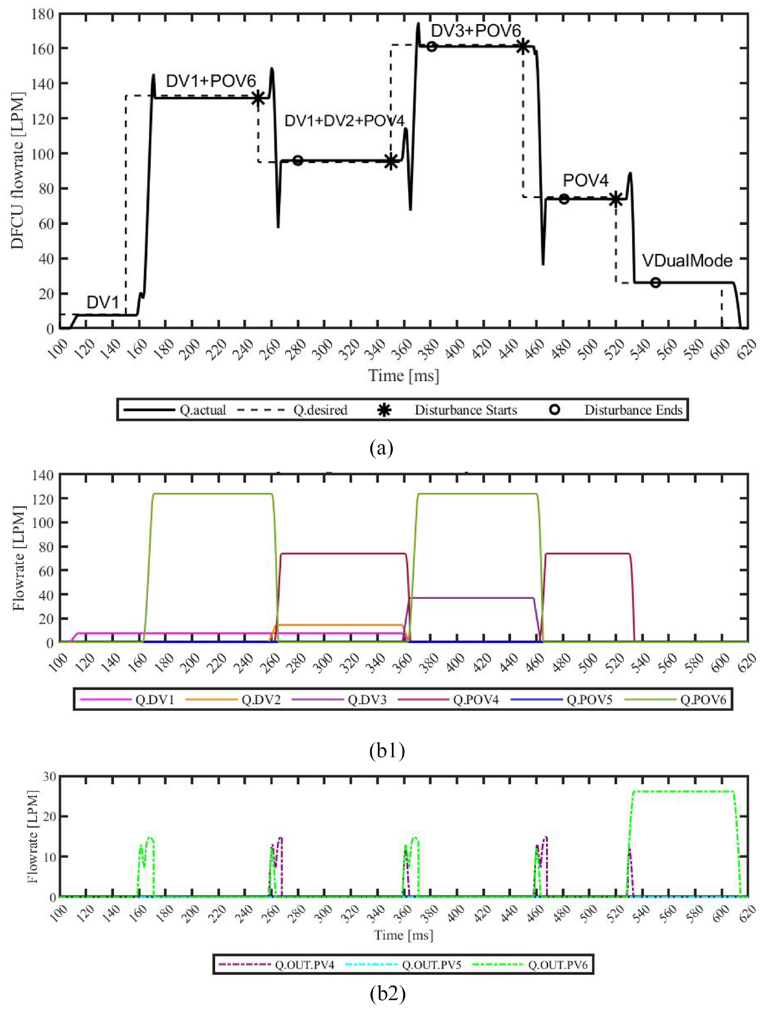
(a) Schematic diagrams for flow disturbances in DFCU (n = 6 + 1). (b1) Corresponding direct and pilot operated valves flow, (b2) Corresponding pilot valves flow.
Notably, in the studied simulated system, fluid inertia for the conduits was neglected. While the Simulink model captures nuanced flow fluctuations, in reality, due to fluid inertia and flow sensor resolution, these fluctuations will be less sharp and challenging to be measured. This underscores the importance of pressure readings over flow measurements when implementing practical testing, as discussed by researchers at Zhejiang University when testing a high-performance pilot-operated directional valve. 48
Automated script for identifying flow disturbances
This above detailed analysis of the flow disturbances sheds light on the system complex dynamics, highlighting the importance of the temporal interplay between the valves operations and the resultant fluid flow disturbances. To rectify this, an innovative method was introduced that measures the flow disturbances (Crests and Troughs) in a fluid flow system by analyzing valves activity and flowrate changes. A script examines valve signals, collecting their time-series data. It computes temporal derivatives (At least one valve opens while another closes) to capture valve operation, thus flagging flow disturbance starts
For each disturbance pair (p) timing, characterized by a start point and end point, define the time subvector
After determining the timing of each pair, next is to calculate the flow disturbance volumes. Let D, for each disturbance pair (d), where D denote the set of all disturbance pairs flow, let

and

Flow switching cases may involve multiple flow disturbances in the form of crests and troughs. To accurately locate these disturbances, the time interval
Additionally, it is important to note that if a crest or trough lies between the baselines, the controller can still detect their presence. However, the calculation of their volumes is not performed in such cases, as only crests or troughs outside the baselines ranges are considered flow disturbances.
Results and discussion
Standard “DFCU (n = 6)” versus dual operation “DFCU (n = 6 + 1)” comparison
Improved tracking accuracy for small flow rates
The graph below, Figure 8(a), illustrates the improvement in performance when dual function is implemented in the DFCU at smaller flow rates. However, as explained in Chapter 3, the number of flow disturbances also increases as shown in Figure 8(b). More analysis of the incident of the flow disturbances shows that flow disturbances predominantly occur at intermediate flow rates, while being notably absent at the lower and upper extremes of the flowrate spectrum. This is due to at lower and upper extremes only the direct operated valves are switching (Figure 9), and their high speed and uniformly modeled response time ensure that no noticeable flow disturbances occur.

Examination of flow disturbances in standard DFCU (n = 6) and dual mode DFCU (n = 6 + 1). (a) DFCU flowrate at 5 bar and (b) corresponding DFCU peak distribution.

DFCU (n = 6) (Top) versus dual mode DFCU (n = 6 + 1) (Bottom) switching states.
Additionally, the width of the flow disturbance peaks at a mere 15 ms, determined at pressure drops ranging from 5 to 20 bars over the DFCU. While the magnitude of the crests can vary by as much as 20% from the reference signal, the magnitude of the troughs, which exhibit the greatest deviation, can diverge by 50%. This is due to troughs caused are by the main valves, which have higher flow rate capabilities, thereby emphasizing the higher priority of mitigating such errors over other types of flow fluctuations.
Depicted in the following Figure 9 are the corresponding valve states for each scenario. It’s noteworthy that the frequency of valve switching rises in the dual-mode configuration, DFCU (n = 6 + 1) case. This heightened activity uncovers the operational complexity introduced by the additional mode.
Analysis of flow disturbances
Table 2 is utilized to provide a more detailed quantitative analysis of the flow disturbances observed in Figure 8, comparing the standard DFCU (n = 6) and dual mode DFCU (n = 6 + 1).
Flow disturbance analysis over Figure 8 course reaching Max Q of 364 LPM.

To sum up, Table 2 shows that employing the dual-mode DFCU (n = 6 + 1) expands the range of flow combinations available to achieve the desired flow rate, While this innovation introduces new and diverse possibilities for flow rates, it also increases the occurrence of flow disturbances (crests and troughs). These disturbances can be effectively managed using previously studied controllers20,46 or smart optimization algorithms (future research).
DFCU response time at different pressure values
In comparison, the two graphs represented in Figure 10 display the desired and actual flow rates over time, both at a lower pressure of 5 bar and a higher pressure of 100 bar. In both scenarios, all the valves in the DFCU (n = 6 + 1) are opened. Further analysis shows that pressure drop slightly influences response time, due to the DFCU combination of direct and pilot-operated valves. Direct operated valve response times, as modeled by Ketonen and Linjama,
16
remain consistent despite pressure changes, when examined at the specified testing conditions. Although the pilot-operated valves output flow rates increase when pressure rises from 5 to 100 bar (

DFCU response time demonstration.
For 5 bars, the system opening and closing times are 21 and 16 ms respectively. At 100 bars, the opening response time slightly improves to 15 ms, while the closing time, already saturated, remains at 15 ms. This analysis overlooks flow forces and friction complexities, potentially impacting response time accuracy. A secondary observation is that the rapid closure of the direct-operated valves, compared to the pilot-operated valves, results in a sloped or chamfered appearance at the top right side of the flow curve.
Effect of response time and coefficient of discharge on tracking accuracy
POV6 has been selected as the subject of a controlled study to examine the influence of variations in the response time and coefficient of discharge on flow disturbances (crests and troughs). As shown below in Figure 11 in the first scenario, it is observed that a reduction of 20% (correspond to mere 3 ms) in the response time of In-PV6 and Out-PV6 valves leads to a consequent impact on the response of main valve POV6. This, in turn, results in an increase of flow disturbance by 27%.
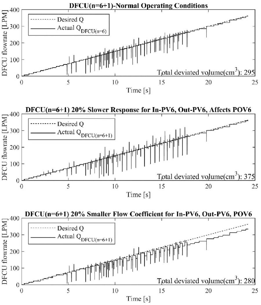
Flow sensitivity analysis.
In the secondary analysis, a 20% (same percentage as in the response time test) fault has been intentionally introduced into the discharge coefficient of In-PV6, Out-PV6 and POV6 valves, a plausible scenario attributable to imprecise modeling, such as ignoring thermal effects or factors like fluid viscosity. This alteration impacts flow disturbances via two mechanisms: (1) it introduces minor variations in the main valve (POV6) response time due to changes in the flow rate of the pilot valves (In-PV6 and Out-PV6), and (2) it influences the main valve discharge coefficient, thereby modifying the flow magnitude and consequently the intensity of the flow disturbance. 20 The system incorporates diverse origins of flow disturbances (as outlined in Section “Quantifying flow disturbances in DFCUs”), and these disturbances may either counterbalance or amplify each other, based on not just their temporal sequencing but also their intensity. Hence, the results show that a 20% change in the coefficient of discharge affects the system dynamics by 5%.
Although significant deviations are observed at 20% faulted flow coefficient scenario, the primary interest lies in the flow disturbances (crests and troughs), emphasizing the necessity of utilizing the specialized approach detailed in Section “Quantifying flow disturbances in DFCUs” to quantify and measure only the flow disturbances. If traditional methods (such as RMS method reviewed and critiqued in Section “Quantifying flow disturbances in DFCUs”) were employed, one might incorrectly assume that the coefficient of discharge has a more substantial effect on flow disturbances than the response time.
Conclusion
In conclusion, this article presented a comprehensive study on the mathematical modeling and controller implementation of a DFCU (n = 6 + d), including both stroke limited pilot-operated and direct-operated valves. An innovative dual operation scenario was introduced, enabling the achievement of dual discrete flow rates from the same pilot-operated valve assembly.
The article discussed the types of flow disturbances in the DFCU, originating from the switching of main valves and pilot valve openings, which escalate in case of employing pilot operated valves. A comparative analysis of different pilot valve assembly configurations showed the advantages of using DFCU (n = 6 + 1) as a compromise option between precision and flow peaks. Notably, the troughs were accounted for most of the errors when compared to the crests deviations. It was also noted that 20% alteration in valve response time has more than five times the impact on flow disturbance errors compared to changes in the discharge coefficient.
However, there are some limitations and drawbacks that need to be considered. The increased possibilities of valve switching observed in the dual-mode configuration indicates the operational complexity introduced by the additional mode. The model was simplified by neglecting the flow forces acting on the valve, friction, and fluid inertia. Lastly, the sensitivity analysis highlighted the impact of deviations in output flow and in switching times, emphasizing the need for precise control and calibration (optimization) of the DFCU components to correctly predict flow disturbances.
Footnotes
Appendix
Acknowledgements
The authors would like to express their gratitude to Jyrki Tammisto (Project Researcher at TAU) for his invaluable comments.
Handling Editor: Sharmili Pandian
Declaration of conflicting interests
The author(s) declared no potential conflicts of interest with respect to the research, authorship, and/or publication of this article.
Funding
The author(s) disclosed receipt of the following financial support for the research, authorship, and/or publication of this article: This work was supported partially by the Ministry of Education in Finland, represented in Tampere University Automation Technology and Mechanical Engineering unit (ATME), specifically within the Innovative Hydraulics and Automation (IHA) Lab. And partially by the Egyptian Cultural Affairs and Missions.