
Abstract
The use of computer-based automation and control systems for smart sustainable buildings, often so-called Automated Buildings (ABs), has become an effective way to automatically control, optimize, and supervise a wide range of building performance applications over a network while achieving the minimum energy consumption possible, and in doing so generally refers to Building Automation and Control Systems (BACS) architecture. Instead of costly and time-consuming experiments, this paper focuses on using distributed dynamic simulations to analyze the real-time performance of network-based building control systems in ABs and improve the functions of the BACS technology. The paper also presents the development and design of a distributed dynamic simulation environment with the capability of representing the BACS architecture in simulation by run-time coupling two or more different software tools over a network. The application and capability of this new dynamic simulation environment are demonstrated by an experimental design in this paper.
Keywords
1. Introduction
Through the use of recent technological advances in computers and communication protocols, a computer-based automation and control system is frequently used to replace so-called hardwired controls with control strategies implemented in software. Such a technology in Automated Buildings (ABs) generally refers to the Building Automation and Control Systems (BACS) architecture. In order for BACS technology to adapt ABs to changing requirements, such as the needs of a building’s occupants and environmental changes in a building by control systems design, experiments or similar analyses must be conducted to improve the automation and operational integrity of building heating, ventilation, and air-conditioning (HVAC) equipment and lighting components. 1 However, experiments are time consuming as they require an occupied period, that is, at least 24 hours including an unoccupied period, to obtain the results, and because implementing BACS architecture in a real building is expensive. For this reason, this paper deals with the development and implementation of a distributed dynamic simulation environment with the capacity to similarly represent the BACS architecture in simulation by run-time coupling two or more different software tools over a network.
The current situation is that representing BACS architecture in simulation by means of a single software tool or two different simulation tools running on a single computer is complex and even more challenging because it requires taking into account the physical distance of a network in control loops so as to emulate the real-world applications of BACS as closely as possible. It is also important to represent the BACS architecture in simulation by distributing multiple different software tools at run-time over a network to enable assessment of distributed building control applications by predicting the overall effect of innovative control strategies in ABs (see Yahiaoui et al. 2 and Yahiaoui 3 ). As there exists a software tool for very advanced in control modeling, that is, MATLAB/Simulink, and a domain-based Building Performance Simulation (BPS), the combination of both over a network would result in a rational design of distributed control and BPSs by means of experimental design for representing, as in a similar way, the BACS architecture in simulation. This has an objective to assist architectural use and design of distributed control applications in ABs in the form of combined simulations in heterogeneous systems (i.e., different operating systems (OSs) with different access technologies). Although there exist several tools for BPS, such as ESP-r, Trnsys, and Energy+, ESP-r was chosen for this study because of its modular programming.
Previous and ongoing work by others, especially with a focus on run-time coupling, include for example coupling between lighting and building energy simulation (see, e.g., Janak 4 ), between computational fluid dynamic programs and building energy simulation, 5 and between building performance and energy systems simulation, 6 as well as using the buildings controls virtual test bed (BCVTB) library (e.g., Wetter 7 ). However, most approaches are often based on coupling of two simulation tools in the synchronous mode, which indeed does not take network dynamics into account. Moreover, these approaches cannot be used to represent distributed building control applications in simulation, as they are performed in BACS architecture. As a result, a middleware for distributed dynamic simulations by run-time coupling between a software system for control systems design and one or more BPS tool(s) over a network is developed for a more general and wider applicability.
2. Development and implementation
2.1. Description of BACS architecture
ABs are a class of buildings that are automatically supervised and controlled by or from a central computer-based monitoring and control system, such as distributed control system (DCS) architecture, or more specifically BACS architecture. Therefore, BACS is an example of a DCS because it uses a computer-based control system to replace so-called hardwired controls with control strategies implemented in software. The basic function of BACS is to automatically monitor and control a wide range of building performance applications, including HVAC equipment, lighting components, and other tasks, such as access control, energy management, and fault diagnoses, in a building or a group of buildings over a network. While this technology has several advantages, it also brings inevitably problems due to the network. Figure 1 shows a complete BACS architecture that can be described at four main levels2,8,9:
the management level consists of a central computer used for managing and analyzing data, communicating with external systems, and operating building equipment and components;
the network level consists of an open protocol connected to the network through routers used for data exchange between the central computer and substations (or terminals);
the automation level consists of one or more substations used for interfacing building HVAC equipment and lighting components to the network;
the field level represents the low level where building HVAC equipment and lighting components (i.e., sensors and actuators) and final users are located.
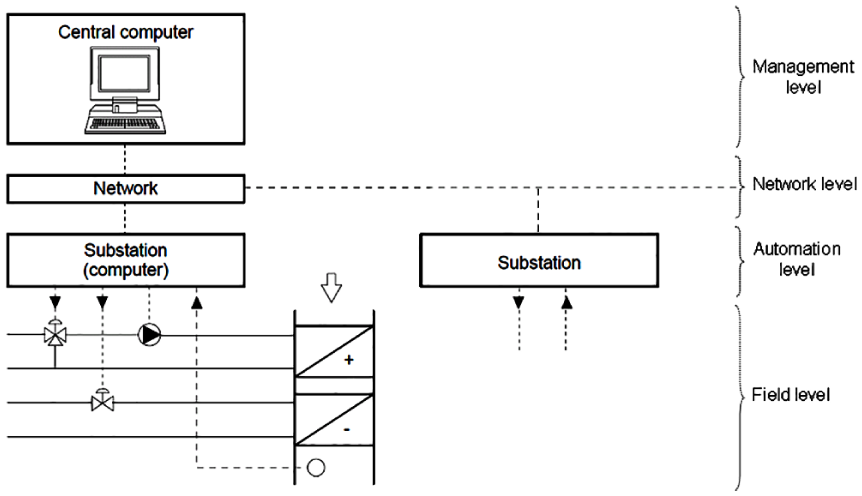
Building Automation and Control Systems architecture.
Because BACS uses a network for data exchange between a central computer and substations, this can degrade both the performance and the stability of HVAC equipment and lighting components in buildings. The most straightforward way to evaluate such problems without a full-scale implementation of BACS is through a modeling and simulation approach. Therefore, successful development and application of BACS require a scalable simulation platform that supports the evaluation and verification of different control and network algorithms. As a consequence, a distributed simulation environment was developed and implemented mainly for BACS to simultaneously simulate building control applications and communication network dynamics.
2.2. Development and design of run-time coupling
The design of run-time coupling between MATLAB/Simulink and one or more ESP-r(s) begins with the definition requirements, and proceeds eventually to conceptual design of the run-time coupling by means of trade-off analysis, and then to detailed design of every part of the run-time coupling being developed. Therefore, a set of requirements were first identified and set forth as the basis for the development and design of the run-time coupling. However, these requirements must then be taken into consideration at the early stage of development. Among the most important of these requirements are the following4,10,11:
the ability for run-time coupling between MATLAB/Simulink and one or more ESP-r(s) to run on a heterogeneous network as on Windows and Unix OSs;
the ability for run-time coupling between MATLAB/Simulink and one or more ESP-r(s) to support data exchange over a network that is either unidirectional or bidirectional;
the ability for run-time coupling between MATLAB/Simulink and one or more ESP-r(s) to support different data-exchange formats, including ASCII, binary, and Extensible Markup Language (XML);
the ability for run-time coupling between MATLAB/Simulink and one or more ESP-r(s) to support different communication modes, including synchronous, asynchronous, and partially synchronous (or asynchronous); and
the possibility for run-time coupling between MATLAB/Simulink and ESP-r to enable simulations with either a real building (e.g., building emulator) or a control test-rig (e.g., hardware in the loop testing), in which the Inter-process Communication (IPC) must then be platform independent.
After evaluating and selecting the most suitable solution among a number of possible options, using network (or internet) sockets has been chosen and approved by Yahiaoui et al.2,12,13 as the best means of implementing run-time coupling between MATLAB/Simulink and one or more ESP-r(s) because they meet all the requirements of the run-time coupling, including those described above, and they can also be used to represent in simulations of real-time building control implementations over a network, as shown in Figure 1.
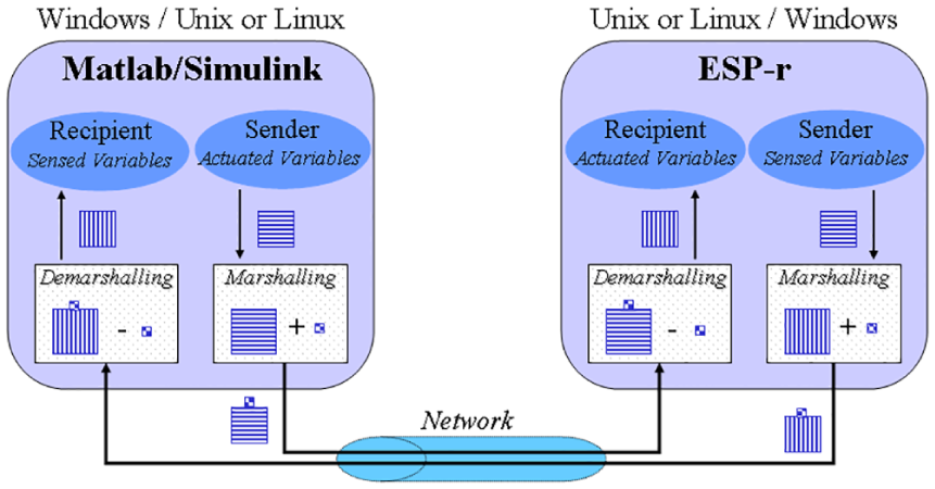
Run-time coupling between MATLAB/Simulink and ESP-r.
Network sockets are an IPC mechanism that is used for run-time coupling between ESP-r and MATLAB/Simulink to support modeling of a building model and its external control systems separately. Both the building model and its control systems can be located on different machines running different OSs, such as Unix and MS-Windows. They also work together by exchanging data in a common format, including ASCII, binary, and XML, through a network, and by supporting communication modes, such as synchronous, asynchronous, and partially synchronous. Figure 2 illustrates the proposed approach to run-time coupling between MATLAB/Simulink and ESP-r.
Run-time coupling is implemented in such a way as to facilitate data exchange between MATLAB/Simulink and ESP-r when they are concurrently operating either on the same machine or to increase the speed of simulations, on separate machines connected by a network. In addition, when MATLAB/Simulink and ESP-r are located on different machines running over different OSs and/or use different data formats by initiating network protocols, such as LonWorks and BACnet, run-time coupling can be run to support portability and distributed dynamic simulations over a heterogeneous network (i.e., on different machines with different OSs and/or different data format protocols). For this reason, in this work different methods for marshalling and demarshalling (or unmarshalling) data over a network were implemented within run-time coupling to convert data (i.e., sensed or actuated variables) into a form of external network representation and then back to their native format before being accessed by a building model and its control systems, respectively.
2.2.1. Detailed design of run-time coupling
In order to implement run-time coupling between MATLAB/Simulink and ESP-r with network sockets, the C/C++ programming language was used of which socket libraries were originally implemented. As neither MATLAB/Simulink nor ESP-r have simple interfaces with socket Application Programming Interfaces (APIs), a detailed design of the run-time coupling is proposed and implemented with the objective of interfacing socket APIs to both ESP-r and MATLAB/Simulink, as shown in Figure 3.
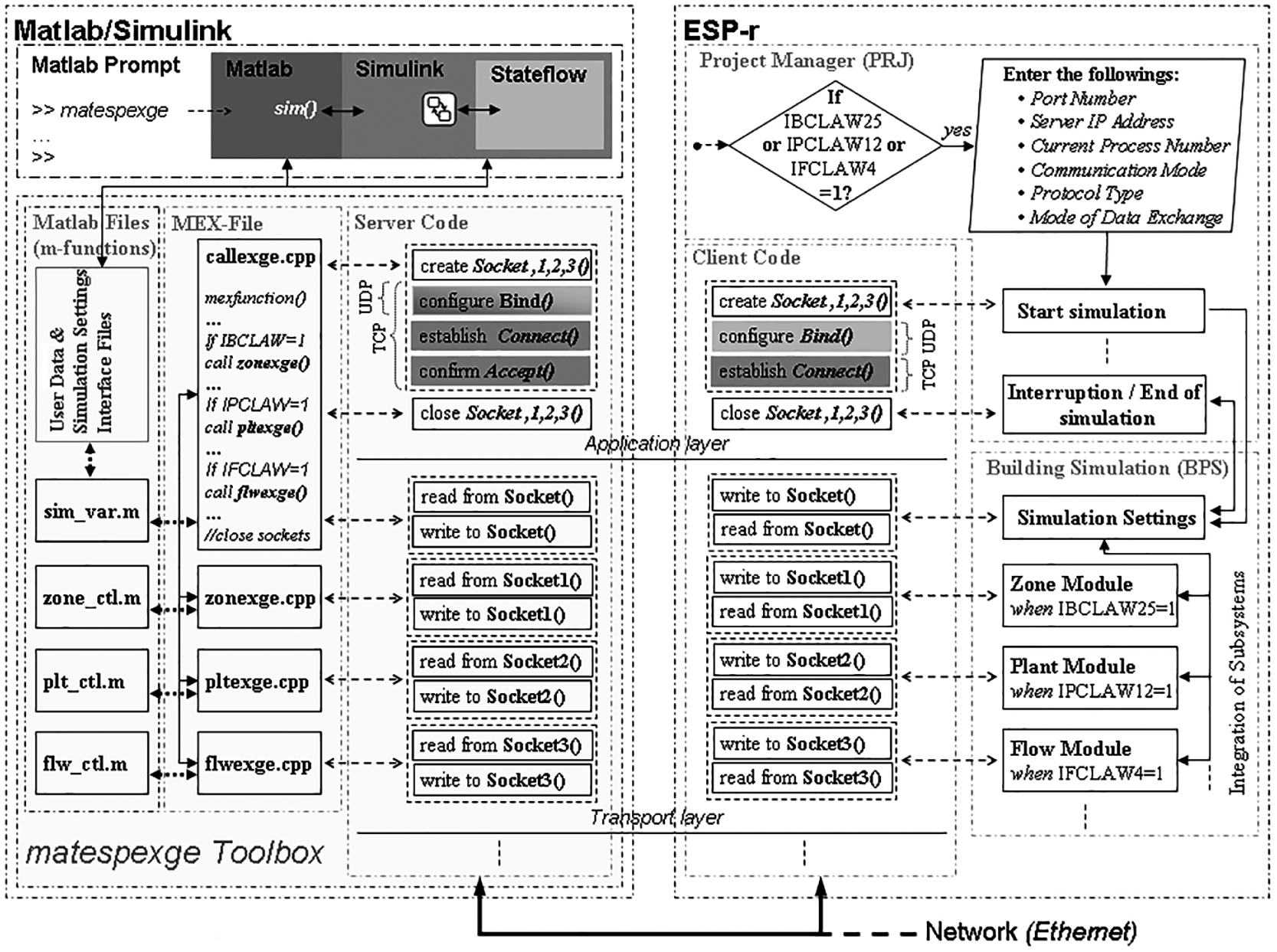
Detailed design of run-time coupling between ESP-r and MATLAB/Simulink.
As the detailed design shown in Figure 3 is based on the idea that run-time coupling should be delivered in such a way that there are no or minor user interferences, the details of the parallel and distributed computations are then hidden to users, while necessary information, such as the port number and Internet Protocol (IP) address of the MATLAB/Simulink location, is provided through user interfaces in order to create sockets that allow one or more ESP-r(s) to exchange data with MATLAB/Simulink. As both datagram and stream sockets are supported, the same socket type should be selected on both sides of the run-time coupling mechanism. By such means, this mechanism can serve as a virtual interface that supports portability between heterogeneous platforms, enables distributed dynamic simulation of BACS, and achieves a higher level of interoperability by using a common middleware platform rather than a non-distributed communication system. Besides this middleware platform, two data encoding methods are integrated to improve interoperability when MATLAB/Simulink and ESP-r are running on heterogeneous environments and to increase the speed of data exchange between a building model and its control systems when both ESP-r and MATLAB/Simulink are running on distant machines connected to a network. The first method of data encoding consists of implementing two modes (ASCII strings and binary codes) to meaningfully and accurately exchange data between a building model and its control systems over a network. The second method consists of using a set of web-based interoperability specifications, such as web services based on XML, in order to enable building models and their control systems to exchange data with a high level of interoperability between ESP-r and MATLAB/Simulink while representing different network technologies, such as BACnet and LonWorks protocols, in a simulation.
The right-hand side of Figure 3 shows how ESP-r and its integrated subsystems (zone, plant, and flow modules) are bound to socket APIs, while the left-hand side of Figure 3 details how the “matespexge” toolbox is implemented to bind socket APIs to MATLAB/Simulink. On the ESP-r side, several subroutines, such as IBCLAW25, IPCLAW12, and IFCLAW4, are added and implemented in a building simulator (BPS) to allow direct data transmission between the subroutines and their parallel programs, which are implemented in the matespexge toolbox during simulation. Other subroutines, such as that for a test function, are implemented in a project manager (PRJ) to determine whether any of the building simulator (BPS) integrated modules invokes an external control system that should be remotely processed from MATLAB/Simulink. If one of these integrated modules occurs, a graphical user interface containing data regarding the port number, server IP address, current process number, communication mode, protocol type, and mode of data exchange appears so that the user can modify and choose specific settings. Initially, these settings are set to default values and correspond exactly to those specified in the matespexge toolbox. Changing these settings is possible, although MATLAB/Simulink and ESP-r must use the same entries to ensure their connection. On the MATLAB side, the matespexge toolbox is designed with graphical interfaces in order to allow users to differentiate between sensed and actuated variables that should be exchanged with ESP-r. Executing the matespexge toolbox at the MATLAB prompt results in a graphical user interface appearing and displaying the machine IP address of the MATLAB/Simulink location, which should match the ESP-r IP address. As MATLAB is the server of ESP-r client(s), executing first the matespexge toolbox is essential before initiating simulation in ESP-r.
As shown in Figure 3, run-time coupling between ESP-r and MATLAB/Simulink is designed in a layered fashion, where the upper Open Systems Interconnection model (OSI) layers resolve different aspects of the communication process. As ESP-r consists of legacy Fortran codes, the programs that operate building simulation and those that initiate and terminate it are positioned and executed in different steps (i.e., the first programs are executed every time step during the simulation period, while the second programs are executed only when initiating and terminating the simulation). Placing functions that open and close sockets in the first programs would certainly incur significant delays while exchanging data with MATLAB/Simulink during simulation, and opening and closing sockets at every time step could lead to computer failures.
The main advantages of this developed run-time coupling are that it permits any simulation of a building model and its control systems to be built separately using ESP-r and MATLAB/Simulink, respectively, and that it provides the preferred means to handle interoperability tasks, especially cross-interdisciplinary data integration and exchange between ESP-r and MATLAB/Simulink with no or minor user interferences. Therefore, it requires only modeling a building model on ESP-r and its control systems on MATLAB/Simulink, and then indicating their interfaces by specifying the port numbers, modes of exchange, or variables that they will use to import or export data to or from each other.
2.2.2. Interfacing client socket to ESP-r
Because ESP-r (see, e.g., ESRU 14 ) is almost completely written in the Fortran programming language and socket APIs can only be implemented in programming languages such as C/C++, mixed-language programming using Fortran and C++ must be used to interface between Fortran and C/C++ programs. 15 Therefore, mixed-language programming is used to develop and implement an approach combining a Fortran common block with global C/C++ extern data structures (or extern structs) of the same name in order to enable the addition of new variables that need to be exchanged with MATLAB/Simulink without making large modifications in the existing programming codes.
ESP-r was modified and extended to enable users to obtain data on sensed and actuated variables in the external control systems of building zones, plant components, and/or mass-flow networks, and to choose settings (including the server IP address, port number, current process number, network protocol, communication mode, and data-exchange format) for run-time coupling. The added Fortran subroutines that exchange data with MATLAB/Simulink and functions indicate when initiating and ending simulations are combined together with socket APIs of the C/C++ client code separately. The C/C++ client code was developed in a hierarchical way in order to support all possible combinations of exchanged variables and settings that a user could choose in run-time coupling with MATLAB/Simulink. Compiling the modified and extended ESP-r code together with the socket APIs of the C/C++ client code generates executable ESP-r, respectively, and allows ESP-r to run as a client process.
2.2.3. Interfacing server socket to MATLAB/Simulink
MATLAB/Simulink 16 has a built-in utility called MATLAB EXecutable (MEX) that is often used to convert C or C++ programs to a MEX format. The original sense of the MATLAB/Simulink word represents two different environments, which are a high-level technical programming language and a graphical block-diagram interface. Depending on which environment is interfaced, two main approaches can be used to link external programs written in C/C++ code as follows.
For MATLAB, MEX files are used with dynamically linked programs that, when compiled, can be called from within MATLAB in the same way as M-files or built-in functions. In the case that we need to deal with Simulink, the links can be performed between each other by just using “sim” functions.
Practically the same procedure is adopted by Simulink, although MEX S-functions are used with dynamically linked programs that, when compiled, can be called from within a Simulink block diagram. However, when there is a need to deal with MATLAB, the link should be done via M-file S-functions that are more complicated than using a straightforward “sim” function.
The first approach is preferable not only because it is less complex than the second approach, but also because it offers more advantages, such as the following: (1) the capability to manage a high number of exchanging variables simultaneously; (2) the versatility needed to meet the requirements of run-time coupling; and (3) the ability to implement functionalities that are not accessible to M-file S-functions.
Although the MEX files were originally designed to allow the inclusion of external routines written mainly in C/C++, they are also capable of integrating external shared libraries, such as socket APIs, into MATLAB. For these reasons, a MEX file was used for the development and implementation of the “matespexge” toolbox.
By combining MEX file functions and socket APIs, access from ESP-r to MATLAB and Simulink functionalities, especially to the application toolboxes for advanced control systems, is realized by just invoking the name “matespexge” from the MATLAB prompt. Once the matespexge toolbox has been executed, a graphical user interface, including icons and menus, will display and provide the dialogue for users to create M-files to remotely control a building zone, plant, and/or flow model as built on ESP-r accordingly. Further access from these M-files to Simulink can be obtained by using “sim” functions, although access from Simulink to Stateflow should be obtained by incorporating a Stateflow block in the Simulink block diagram. Moreover, these M-files include MATLAB functions that contain the left- and right-hand arguments with which the MEX file is invoked. Therefore, the matespexge toolbox was designed with the use of MEX files that includes facilities for enabling run-time coupling between MATLAB/Simulink and one or multiple ESP-r(s). After compiling the matespexge toolbox, a dynamic executable file is generated with an extension corresponding to the OS over which MATLAB/Simulink is running. Within the implementation of the matespexge toolbox, the external routines that specifically exchange data with subroutines for the building zone, plant, and flow network modules of ESP-r are encapsulated into a single MEX file. A global identifier is also integrated to determine which building zone, plant, and/or flow network model will exchange data with the created control file. Due to this fact, the user must provide valid information (i.e., as stated in ESP-r) on the input interface. In addition, as MATLAB is an interactive tool, the handling callbacks from ESP-r are ensured by default in order to access MATLAB/Simulink as a computational engine. For these reasons, the matespexge toolbox is designed in such a way to let MATLAB/Simulink operate as a server process when its created control files are invoked by one of the three ESP-r modules. Because Stateflow can be used together with Simulink for the simulation of Multi-agent Systems (MASs), the use of the matespexge toolbox becomes essential for enabling the integration of advanced control systems, such as hybrid systems and MASs in BPS. It enables a user to interactively build, test, and simulate distributed applications between MATLAB/Simulink and ESP-r(s), even when these software tools are running on separate and different OSs. Therefore, it is a key solution in enabling the analysis of multi-variable control systems of building performance applications (or operations) that had previously not been feasible.
2.3. A practical approach to represent BACS technology in simulation
Although representing BACS technology in simulation, as shown in Figure 1, is difficult if not impossible, this design of run-time coupling between multiple ESP-r(s) and MATLAB/Simulink can allow for identifying practical solutions for the integration of advanced control systems into BPS and improving distributed control applications, such as planning and coordination of control actions, in ABs for better operation. As one of BACS’ constraints is time delays associated with the network, distributed simulations are required to analyze and simulate both the performance and stability of building HVAC equipment and lighting components in ABs. Consequently, the need for distributed simulations originates from the fact that BACS requires the study of both control theory and communication networks in design architecture. 17
By assuming that MATLAB/Simulink represents a central computer and ESP-r represents a terminal in a similar way to BACS architecture, the IPC mechanism used to run-time couple them is indeed designed to support cooperative applications through interoperable middleware that provides a layer facilitating the interface of any building model built in ESP-r with its external control system modeled in MATLAB/Simulink. This has an objective to simplify data management and distribution over a network, provide for the independence and transparency of data exchange between building models and their control systems, and allow web services to be highly portable in distributed simulations, similar to the real-time control applications unfolding in BACS architecture. For this reason, this work has enhanced the traditional approach to run-time coupling between ESP-r and MATLAB/Simulink, as shown in Figure 2, with the addition of involving more ESP-r(s) to represent BACS architecture in simulation. Figure 4 illustrates a new practical approach to distributed control and BPS by run-time coupling multiple ESP-r(s) and MATLAB/Simulink over a network.
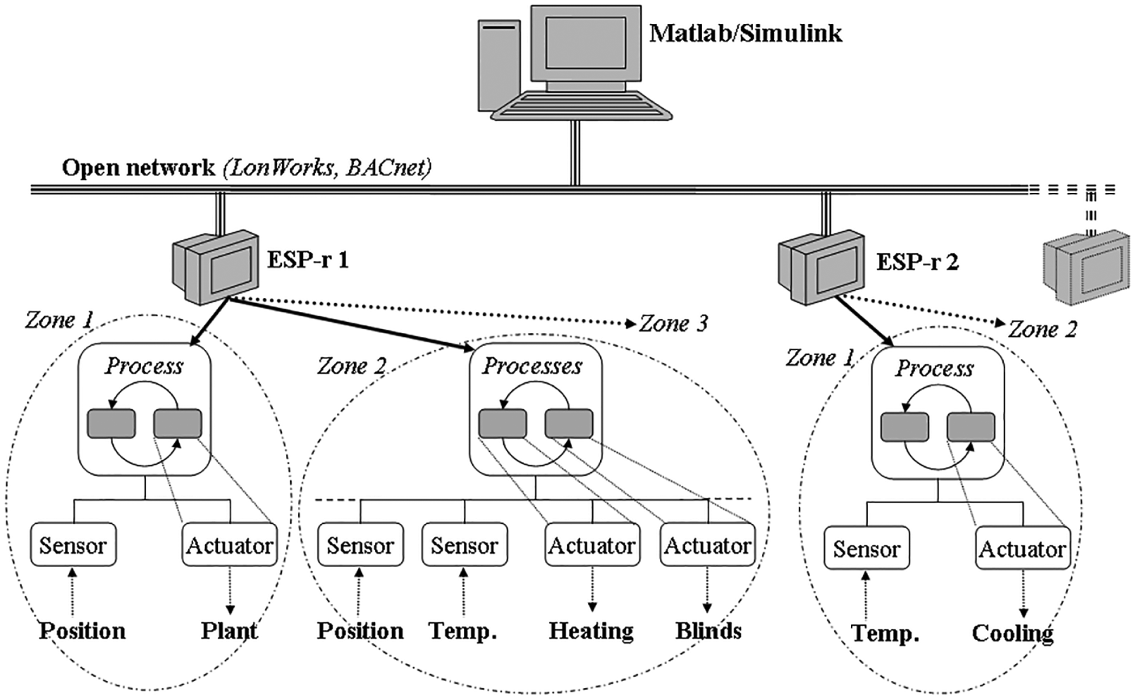
A practical approach to run-time coupling MATLAB/Simulink with multiple ESP-r(s).
As shown in Figure 4, the framework that is implemented to support distributed and parallel simulations by run-time coupling one or more ESP-r(s) with MATLAB/Simulink over a network occurs practically, as in BACS technology. This framework was developed using multi-threads in creating and linking multiple ESP-r(s) to MATLAB/Simulink, for which a similar application to BACS architecture can at once run across multiple machines distributed over a network. 1 In an analogous way to BACS architecture, each ESP-r in the framework must be used to simply model building zone(s), plant system(s), and/or flow network(s), while MATLAB/Simulink must be used to model all their remote control systems. The number of ESP-r(s) that can connect to MATLAB/Simulink is at present limited to at most nine, due to the difficulty in managing all exchanged variables over a network.
2.4. Communication modes in run-time coupling
Because the main feature distinguishing a distributed simulation from a standalone simulation (or a sequential simulation) is the method of advancing simulation time steps, run-rime coupling between MATLAB/Simulink and ESP-r was implemented with all the options accessible from the user interface to specify the number of simulation time steps per hour and to determine whether the simulation should run in a synchronous, an asynchronous, or a partially synchronous mode.
2.4.1. Synchronous mode
The synchronous mode is used when ESP-r and MATLAB/Simulink are run-time coupled and synchronized with the same number of simulation time steps in execution. When either ESP-r or MATLAB/Simulink must wait for incoming data from the other, the number of simulation time steps is defined by ESP-r, which is the client for MATLAB/Simulink, the server. Figure 5 shows how ESP-r and MATLAB/Simulink must wait for each other and exchange data by run-time coupling at several predetermined time steps for the completion of their computations.
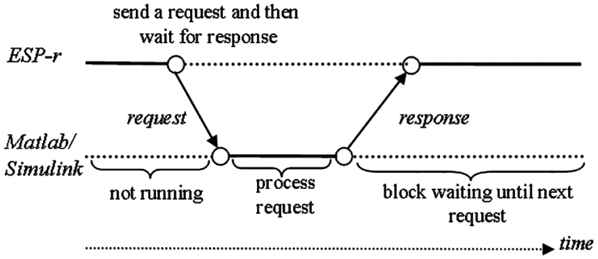
Run-time coupling between ESP-r and MATLAB/Simulink in the synchronous mode.
Because both ESP-r and MATLAB/Simulink are executed sequentially, the exchange of data in this mode blocks the entire simulation at each predetermined time step until the data exchange has been totally completed. Therefore, when MATLAB/Simulink and ESP-r are run-time coupled in the synchronous mode, the time constraints of scheduled transitions must be satisfied by such means as adjusting the timing of a control loop for several applications.
2.4.2. Asynchronous mode
The asynchronous mode is used when ESP-r and MATLAB/Simulink are run-time coupled and processing separately from each other, and not synchronized totally. As such, neither ESP-r nor MATLAB/Simulink must wait for incoming data from the other and can continue their computations with the existing data, although the data might be outdated, until the updated data become available for computation. Running distributed simulations in the asynchronous mode can be positive in some cases because ESP-r and MATLAB/Simulink can be computed with different numbers of simulation time steps, although in other cases the accuracy of the obtained simulation results cannot be ensured. Figure 6 shows a case where the time step of either MATLAB/Simulink or ESP-r differs from that of the other.
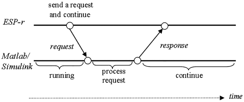
Run-time coupling between ESP-r and MATLAB/Simulink in the asynchronous mode.
The asynchronous mode is difficult to program because it requires that MATLAB/Simulink and ESP-r be run-time coupled in a chaotic manner; that is, in such a way that neither MATLAB/Simulink nor ESP-r must wait for incoming data from the other but instead proceed with its computation until the common task is fulfilled. As run-time coupling between MATLAB/Simulink and ESP-r is implemented with sockets, the asynchronous communication is characterized by the fact that the client and server programs integrated in ESP-r and MATLAB/Simulink, respectively, contain functions that change sockets to the non-blocking mode. Moreover, such a changing signal is returned immediately when the operations reading data from the sockets are invoked by another to indicate that there are no data to be received (see, e.g., Stevens 18 ).
The asynchronous mode was developed in such a way that MATLAB/Simulink began computing once it received the first data from ESP-r. After data were received, ESP-r and MATLAB/Simulink computed independently from each other, and when no data were available to be received, both continued computing using the most recently received data. Using the asynchronous mode allows run-time coupling between MATLAB/Simulink and ESP-r to handle existing data in a manner that may significantly reduce the execution time (see, e.g., Fumagalli and Grasso 19 ). As it imposes no constraints on the control performance, this mode can be used in situations where network-induced time delays are unpredictable. When the synchronous mode is used in these situations, MATLAB/Simulink and ESP-r may have to wait for incoming data for an extended time, which could result in very low or even impractical computation efficiency. Therefore, computation in the asynchronous mode can be useful for the simulation of large building control applications, such as that supported by BACS technology, although it is much more difficult to parallelize due to various independencies in the run-time coupling of MATLAB/Simulink and multiple ESP-r(s).
2.4.3. Partially synchronous mode
The partially synchronous mode is used when ESP-r and MATLAB/Simulink are run-time coupled in partially synchronized (or partially asynchronized) mode, which partly imposes time restrictions on the synchronization of their events. However, the exchange of data between MATLAB/Simulink and ESP-r by run-time coupling does not occur in the lock-time-step, as it does in the synchronous mode. When using the partially synchronized mode, it is assumed that the computation time step and data delivery time of either MATLAB/Simulink or ESP-r is between the upper and lower bounds. Therefore, as a partially synchronous mode lies between the synchronous and asynchronous modes, two possibilities are available for run-time coupling MATLAB/Simulink and ESP-r in the partially synchronized mode: (1) when ESP-r is running in the synchronous mode and MATLAB/Simulink in the asynchronous mode; and (2) when ESP-r is running in the asynchronous mode and MATLAB/Simulink in the synchronous mode. Figure 7 shows both cases of the partially synchronous mode.
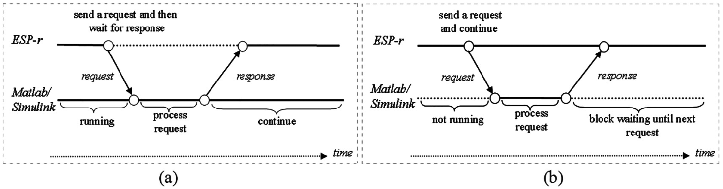
Run-time coupling between ESP-r and MATLAB/Simulink in the partially synchronized mode: (a) ESP-r synchronized and MATLAB/Simulink asynchronized; (b) ESP-r asynchronized and MATLAB/Simulink synchronized.
The partially synchronized mode, when ESP-r is running in the asynchronous mode and MATLAB/Simulink is in the synchronous mode, represents the most realistic communication characteristic of BACS technology (i.e., such that real-time control applications are performed in BACS). Although time delays associated with communication are difficult to predict in BACS architecture, these delays usually have an upper bond, mainly when data are exchanged over a network. Hence, use of the partially synchronous mode leads to less uncertainty than does the fully asynchronous mode, but is very difficult to program due to the timing differences between MATLAB/Simulink and ESP-r (see, e.g., Shamsi et al. 20 ).
3. User interfaces for run-time coupling of ESP-r and MATLAB/Simulink
The user interfaces were developed and implemented on both sides of the run-time coupling in order to facilitate its use (i.e., the setting up of a connection session and exchanging variables). Figure 8 depicts the user interfaces for both sides of the run-time coupling between ESP-r and MATLAB/Simulink.
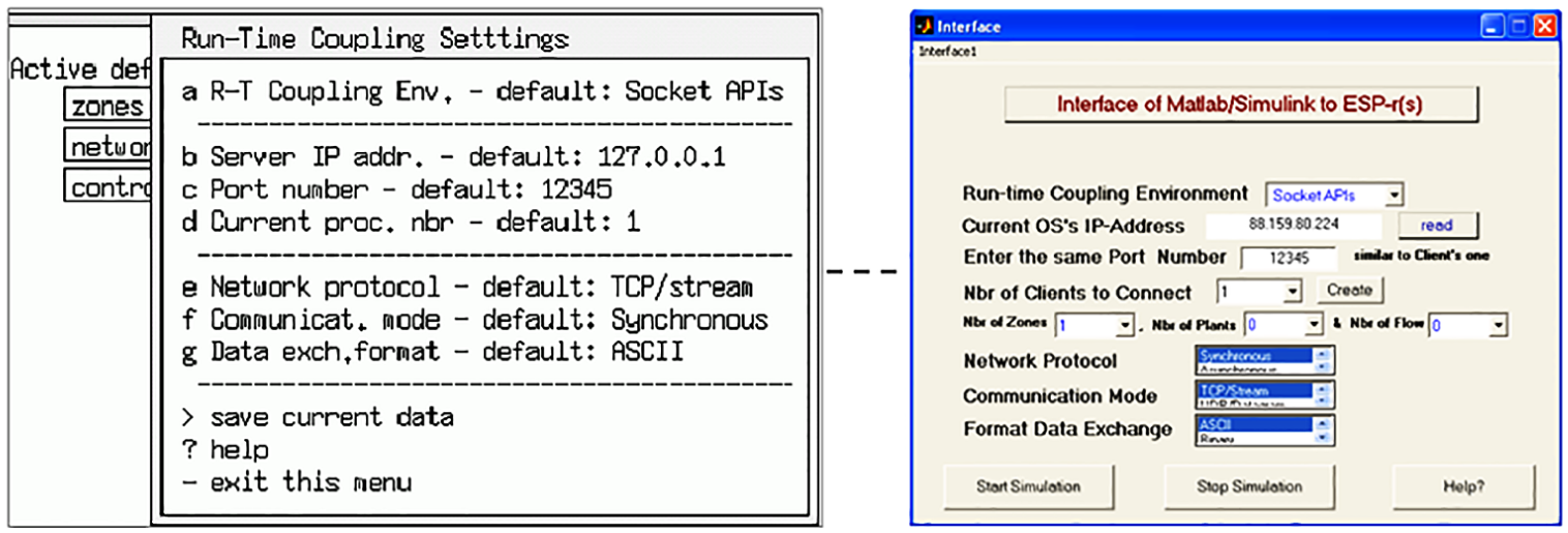
User interfaces for run-time coupling settings: ESP-r (left) and MATLAB (right).
On the ESP-r side, the user interface of the Run-Time Coupling Settings menu can be displayed only if one of the three control laws (zone, plant and systems, and flow network) chooses “Calling MATLAB/Simulink” as a control system/strategy, in which this requires then using external (or remote) control systems, either existing or newly designed, modeled on MATLAB/Simulink. Figure 9 illustrates the upgraded menus of control laws for zone, plant and system, and flow network in ESP-r.
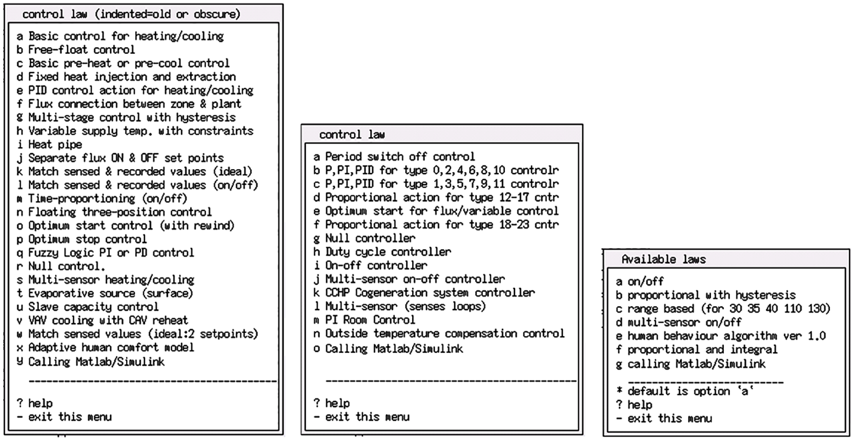
The upgraded menus of ESP-r control laws: zone, plant system, and flow network.
On the MATLAB side, the user interface of the Run-Time Coupling Settings menu is displayed by typing “≫ matespexge” at the MATLAB prompt, as shown in Figure 10. After providing and choosing the necessary entries for run-time coupling with ESP-r, and invoking the creation of one of the three control laws (zone, plant and systems, and flow network), a sub user interface is then displayed. Figure 10 shows this developed and implemented sub user interface on the MATLAB side to set up which sensed and actuated variables should be exchanged with ESP-r by run-time coupling.
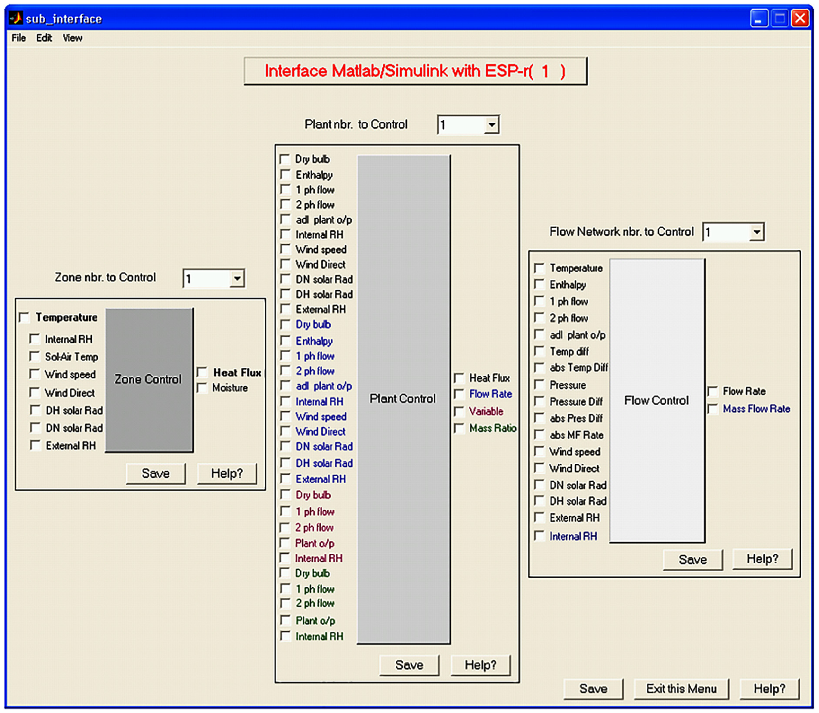
MATLAB sub user interface for zone, plant and systems, and flow network control variables with ESP-r by run-time coupling.
The process of entering all the necessary data required for run-time coupling in MATLAB/Simulink is practically similar to that in ESP-r. In addition, the sub user interface on the MATLAB/Simulink side was designed in the same way, more or less, as in ESP-r. All possible sensed variables (inputs) and actuated variables (outputs) for control of zones, plant and systems, and flow components that ESP-r can exchange by run-time coupling with MATLAB/Simulink are shown in Figure 10.
4. Experimental design
The resulting experimental design, in this work, consists of representing important functions of BACS technology in simulation, and comparing simulation results obtained in different modes of communication using at least two instances of ESP-r(s) run-time coupled to MATLAB/Simulink over a network, referred to as BACS architecture, shown in Figure 3. One way of doing so was to run ESP-r(s) and MATLAB/Simulink on different machines over different OSs like Unix, Cygwin, and Windows. These machines were a Sun Blade Workstation (or Server), a laptop PC, and an office PC, respectively. ESP-r1 was installed over the Unix 10 (or Solaris 10) OS on the Sun Blade Workstation, ESP-r2 was installed over the Cygwin 6.1 on the Windows XP OS on the laptop PC, and MATLAB was installed over the Windows 7 OS on the office PC. The Sun Blade Workstation and laptop PC were connected to the network by an Ethernet LAN cable at a speed of 10 MBps, and at distance of about 7 m from each other, whereas the office PC was connected to the network by an Ethernet LAN cable at a speed of 100 MBps, and distanced from the two other machines (Sun Blade Workstation and laptop PC) by about 1.9 km (i.e., all were located at different places). The compilers used for Fortran and C/C++ programs were of the GNU Public License on Unix and of the Visual Studio 2010 on Windows. Figure 11 shows how distributed dynamic simulations are performed as in a grid computing environment by run-time coupling between MATLAB/Simulink and multiple ESP-r(s) while exchanging data over a network in the form of ASCII, binary, or XML format, and in different communication modes, including synchronous, asynchronous, and partially synchronous, during the simulation.
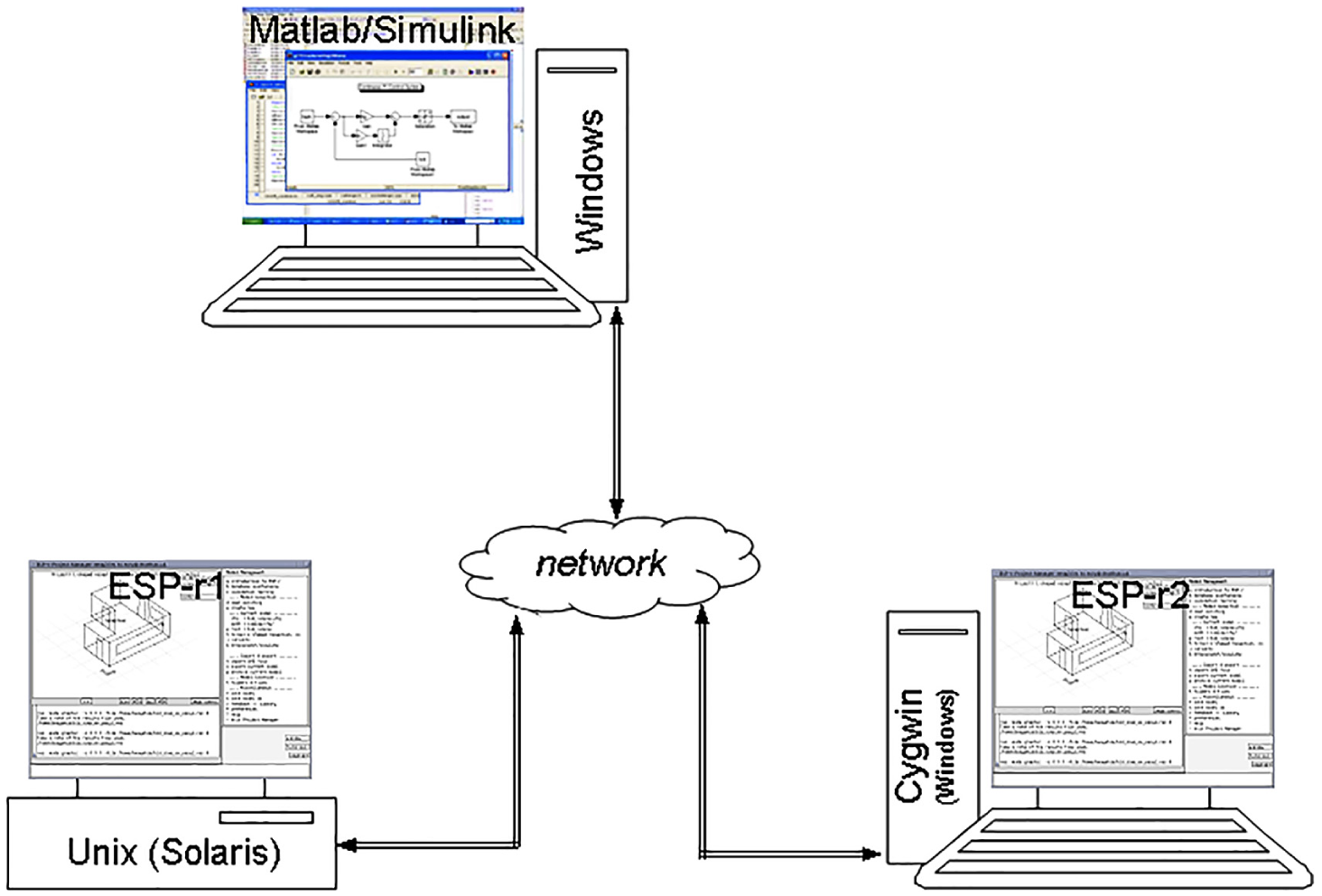
Distributed simulations by run-time coupling of MATLAB/Simulink and two ESP-r(s) as in a grid computing environment.
4.1. Distributed building control application
Studies2,21 have highlighted the importance of run-time coupling between MATLAB/Simulink and ESP-r over standalone simulations in the integration of advanced control systems in BPS for improving all quality aspects of building indoor environments, as well as in the simulation of building control applications requiring multivariable control systems. In order to demonstrate the development and design of run-time coupling between multiple instances of ESP-r and MATLAB/Simulink, and compare the simulation results obtained by different modes of communication, the same building model, which is actually an existing exemplar in ESP-r, was built in two distanced instances of ESP-r, as shown in Figure 8, and in combination with an external (or remote) Proportional Integral (PI) control modeled in MATLAB/Simulink, that is, in the form of a closed control loop. This external PI control is here used simply to regulate the air temperature in a building zone by supplying the required heating flux capacity to it (which is at maximum 3000 W). Figure 12 shows a building model built on two instances of ESP-r (left) in a closed loop with its external PI control modeled on MATLAB/Simulink (right).
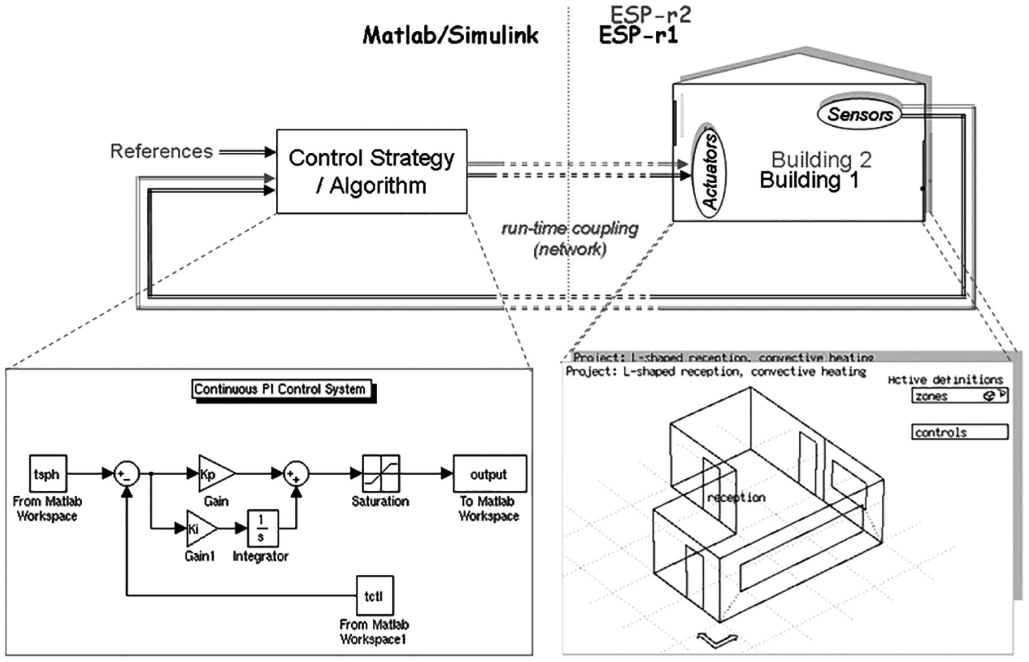
A building model built on two instance of ESP-r (left) with a Proportional Integral (PI) control modeled on MATLAB/Simulink (right).
In this application, the continuous PI control is set to maintain the indoor air temperature (i.e., the control response) at the set-point of 22°C during a period that is valid from 07:00 to 18:00 hours. Consequently, the input to the PI control implemented in MATLAB/Simulink is the error signal created by subtracting the sensed indoor air temperature of the building model built on ESP-r from the set-point. The output of this PI control, a weighted sum of the error signal and its gains, is the actuated heating flux to that building model built on ESP-r.
4.2 Simulation results
The simulation results were obtained with run-time coupling between MATLAB/Simulink and two instances of ESP-r, as shown in Figure 11, while exchanging data in a binary format over a network, and in different modes of communication, including synchronous, asynchronous, and partially synchronous. Figure 13 shows the simulation results obtained for the PI control by run-time coupling between MATLAB/Simulink and two ESP-r(s) in the synchronous mode for simulation time steps of 1 min (a) and 2 min (b).
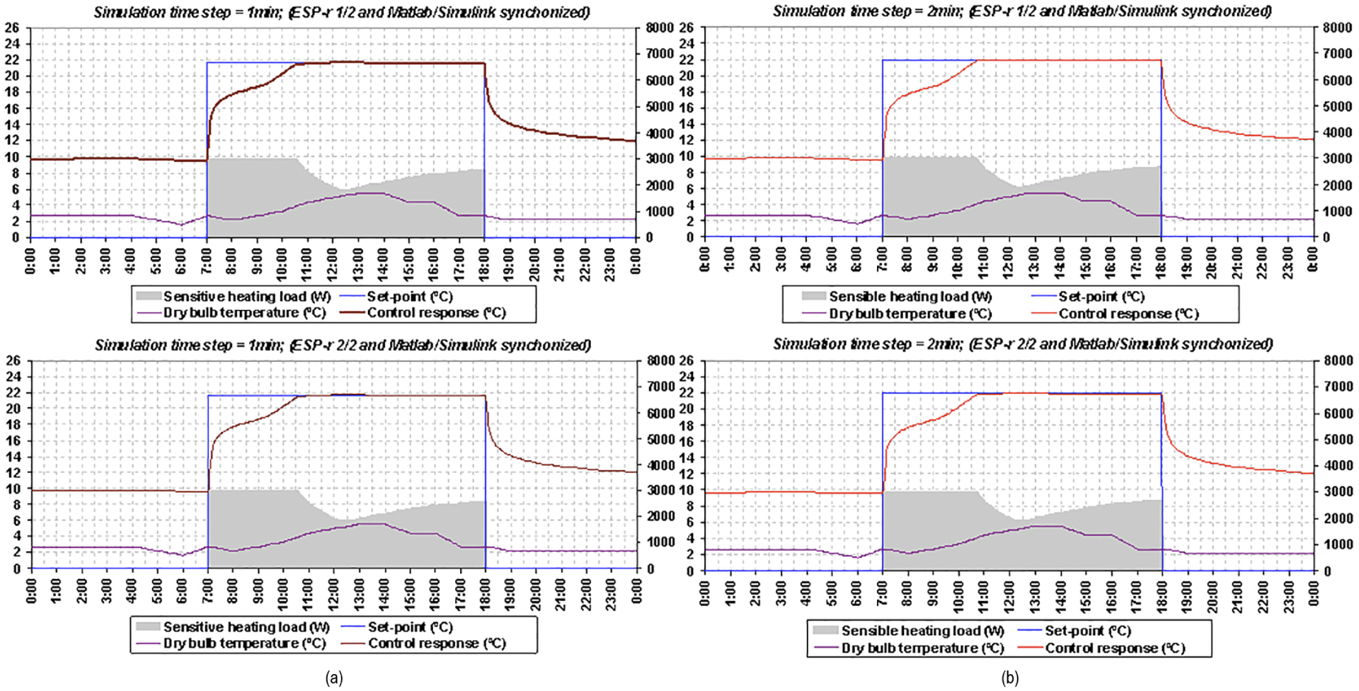
Simulation results obtained for the Proportional Integral control by run-time coupling between MATLAB/Simulink and two instances of ESP-r in the synchronous mode.
By comparing the simulation results obtained by ESP-r1 with those obtained by ESP-r2, it can easily be observed that they are similar and very comparable to each other for both simulation time steps of 1 and 2 min. This is mainly because every coupled MATLAB/Simulink and ESP-r is synchronized at run-time, and thus takes no network-induced time delays into account as both MATLAB/Simulink and ESP-r must wait for each other to receive data during the simulation. Figure 14 shows the simulation results obtained for the PI control by run-time coupling between MATLAB/Simulink and two ESP-r(s) in the asynchronous mode for simulation time steps of 1 min (a) and 2 min (b).
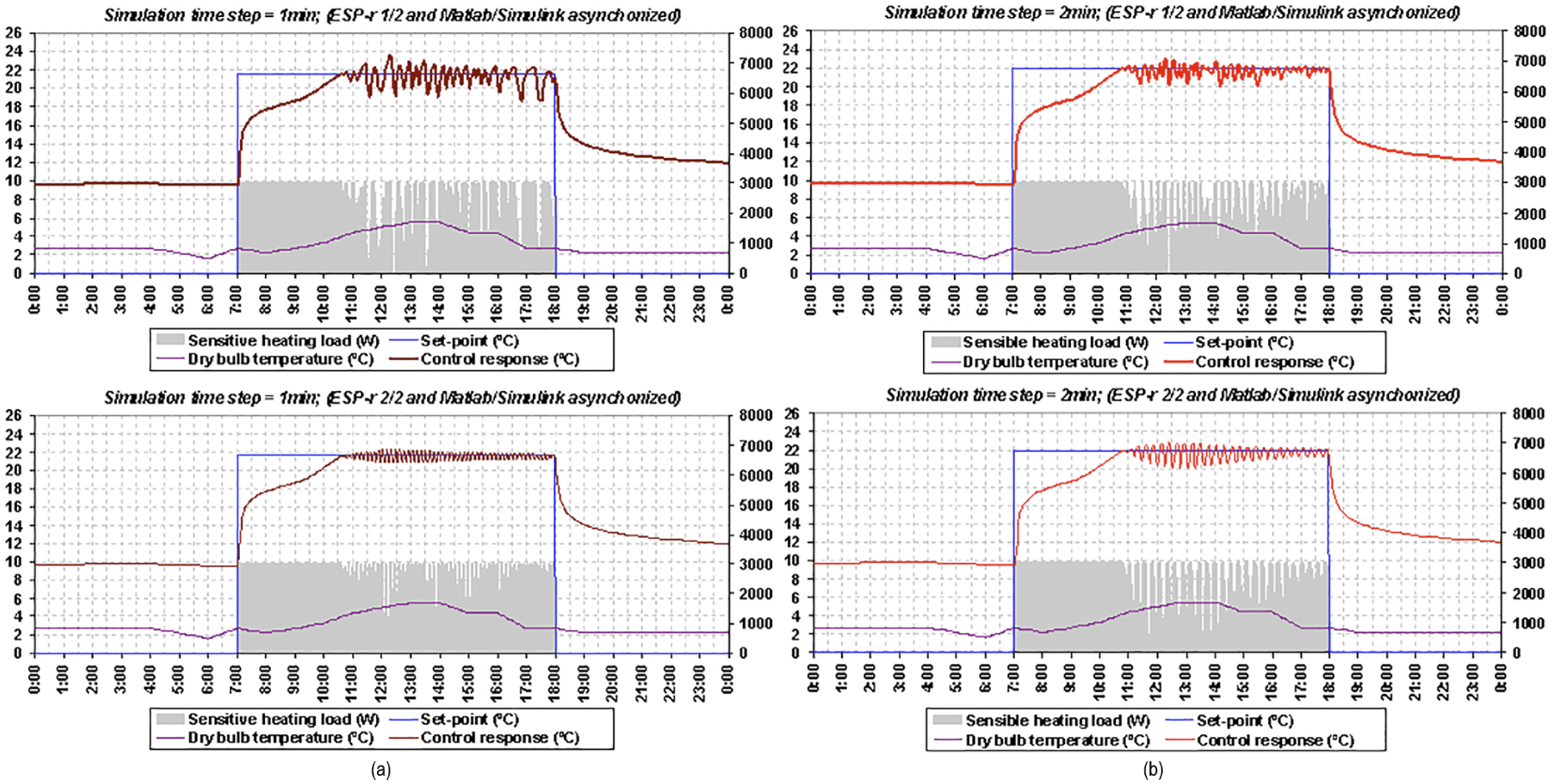
Simulation results obtained for the Proportional Integral control by run-time coupling between MATLAB/Simulink and two instances of ESP-r in the asynchronous mode.
By comparing the simulation results obtained by ESP-r1 with those obtained by ESP-r2, it can easily be observed that they are quite different and incomparable to each other for both simulation time steps of 1 and 2 min. They are different especially when the control action is applied (or valid, which is during the period between 7:00 and 18:00 hours), that is, once the control response has reached the set-point of 22oC because every coupled MATLAB/Simulink and ESP-r is asynchronized at run-time. Neither MATLAB/Simulink nor ESP-r waits for one another to receive data during the simulation as both precede their computations independently. It also appears that these simulation results are different from those shown in Figure 13 for both ESP-r(s) and different simulation time steps. The reason for this difference is because the addition of a network (i.e., physical distance) into a control loop and the use of more than one ESP-r by run-time coupling with MATLAB/Simulink adversely affect the control response due to time delays associated with that network in principal, and time delays associated with the processing capabilities of the used computers for simulation (i.e., over which MATLAB/Simulink and ESP-r run). When considering the control performance, it can be seen from Figure 14 that the control responses are continually influenced by network-induced time delays once they reach the control set-point. Therefore, those results validate the fact that network-induced time delays degrade both the performance and the stability of building HVAC equipment and lighting components. Figure 15 shows the simulation results obtained for the PI control by run-time coupling between MATLAB/Simulink and two ESP-r(s) in partially synchronous mode, that is, when MATLAB/Simulink is asynchronized and ESP-r(s) is synchronized for simulation time steps of 1 min (a) and 2 min (b).
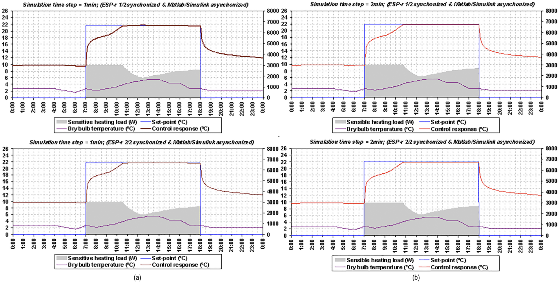
Simulation results obtained for the Proportional Integral control by run-time coupling between MATLAB/Simulink and two instances of ESP-r(s) in the partially synchronous mode (when MATLAB/Simulink is asynchronized and ESP-r(s) is synchronized).
It appears that the simulation results shown in Figure 15 are relatively similar to those shown in Figure 13, because ESP-r(s) are synchronized and wait to receive data from MATLAB/Simulink. Therefore, network-induced time delays in this communication mode have no impact on the control responses because building zones and plant models built in ESP-r wait during the simulation (i.e., at every simulation time step) to receive data from MATLAB/Simulink. Even though MATLAB/Simulink is asynchronized, it does affect the control responses of building models built in ESP-r while being synchronized. However, these simulation results can also be used to validate the design and implementation of run-time coupling between ESP-r and MATLAB/Simulink, as they are accurately similar to those obtained in the synchronous mode. As MATLAB/Simulink uses the latest available data from ESP-r, this proves that when ESP-r is synchronized the simulation results obtained by the two different modes for the two different simulation time steps are perfectly the same. Therefore, this developed distributed dynamic simulation environment by run-time coupling between MATLAB/Simulink and one or more ESP-r(s) over a network is accurately implemented and completely operationalized throughout this study. Figure 16 shows the simulation results obtained for the PI control by run-time coupling between MATLAB/Simulink and two ESP-r(s) in the partially synchronous mode, that is, when MATLAB/Simulink is synchronized and ESP-r(s) is asynchronized for simulation time steps of 1 min (a) and 2 min (b).
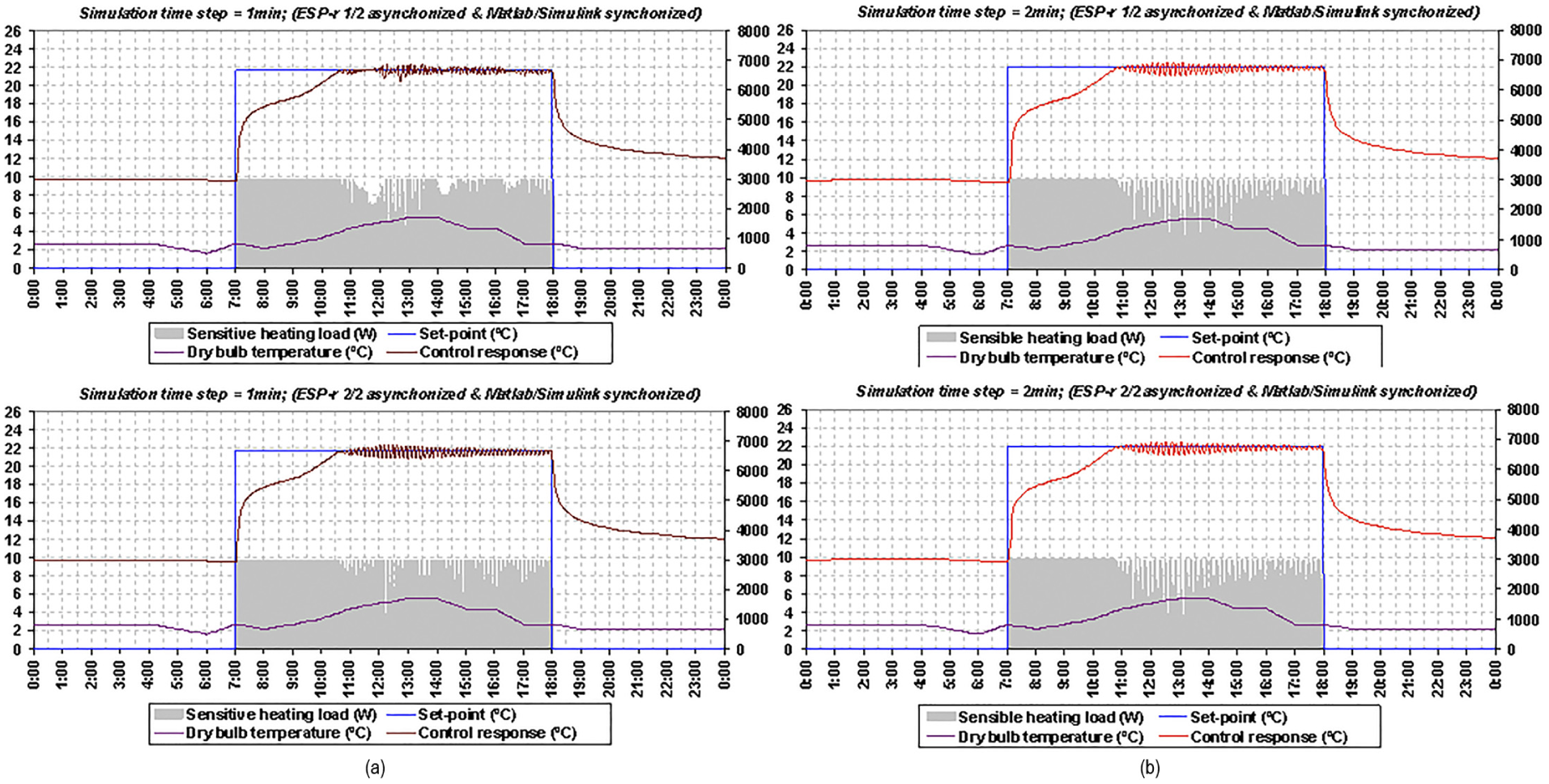
Simulation results obtained for the Proportional Integral control by run-time coupling between MATLAB/Simulink and two instances of ESP-r(s) in the partially synchronous mode (i.e., when MATLAB/Simulink is synchronized and ESP-r(s) is asynchronized).
By comparing the simulation results obtained by ESP-r1 and ESP-r2, as shown in Figure 16, it appears that the results for the simulation time step of 1 min are absolutely different and not comparable to each other, but the results for the simulation time step of 2 min are relatively similar and more or less comparable to each other. From this comparison, it can be deduced that network-induced time delays have an impact on the control responses, depending mainly on the simulation time step, as has actually been stated by Yahiaoui and Sahraoui 17 and Yahiaoui 1 for networked control systems (NCSs). It also appears that the simulation results shown in Figure 16 are different from those obtained in Figures 13 and 15, but partly similar to those obtained in Figure 14, especially for ESP-r2 for the simulation time step of 1 min only, because when ESP-r(s) are asynchronized, the presence of a network in a control loop has an impact on the automation and operational integrity of building HVAC equipment and lighting components, as this adversely affects the control responses depending on the distance of a network and the time step used for the simulation. In principle, this is the communication mode representing real-time control implementations, as they are actually performed in BACS architecture. By assessing the results obtained by ESP-r1 with those of ESP-r2 mainly for the simulation time step of 1 min, it can also be observed that these are different because of less uncertainty that this communication mode leads to compared with the asynchronous mode, and especially the network distance that separates ESP-r(s) from MATLAB/Simulink. In consequence, the use of a network by BACS architecture for distributed control applications in buildings can severely degrade both the performance and the stability of HVAC equipment and lighting components depending on network-induced time delays. While control performance is the measurement (or ability) of how well a controlled system is achieving its desired dynamic responses, despite disturbances caused by changes (such as delays), control stability is the guarantee that a controlled system will remain stable, without affecting its function, even in the presence of a longer time delay and higher magnitude (such as increased overshoot and settling time).
4.3 Insights into control system behavior and BACS enhancement
The relative performance of the different simulation results obtained by run-time coupling between MATLAB/Simulink and two instances of ESP-r in different modes of communication can be mathematically expressed in many different measures, which can be used to evaluate and compare the quality of their controlled responses. The two commonly used criteria are Integral Absolute Error (IAE) and Integral Time-weighted Absolute Error (ITAE), which are defined as follows:
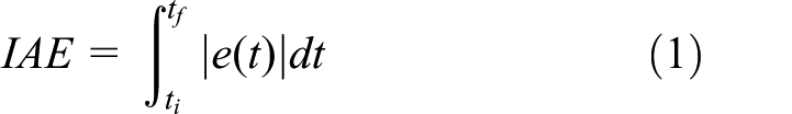
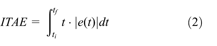
where e is the error difference between the reference (or set-point) and the control response, and
Performance criteria for the control responses.
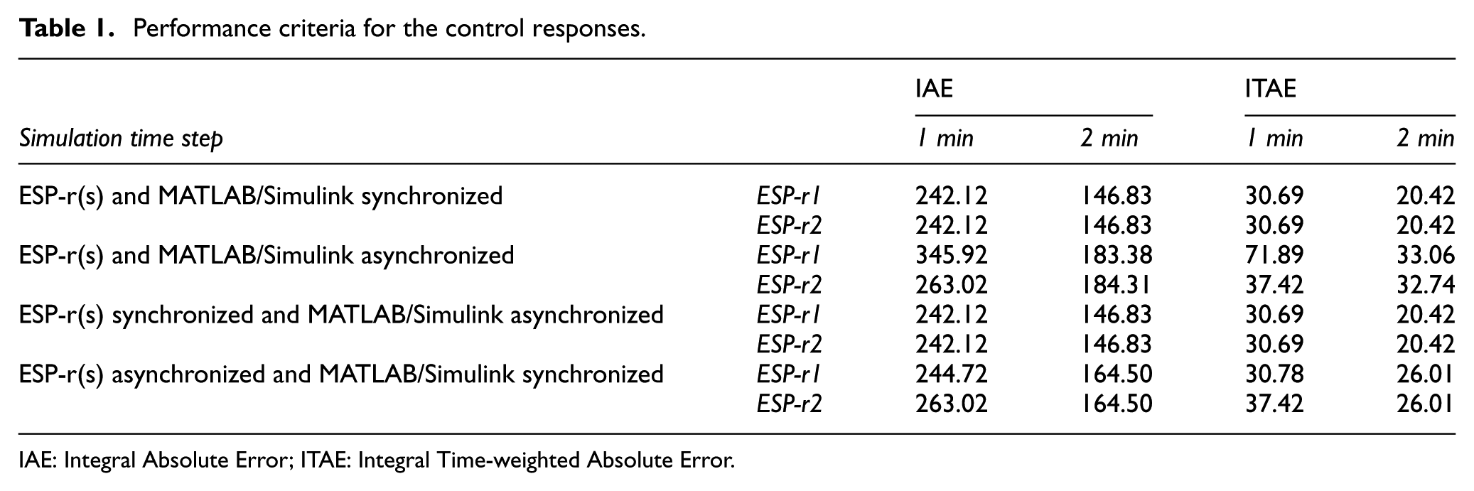
IAE: Integral Absolute Error; ITAE: Integral Time-weighted Absolute Error.
The calculated values of IAE and ITAE criteria confirms that the simulation results obtained by run-time coupling between MATLAB/Simulink and two instances of ESP-r in the synchronous, asynchronous, and partially synchronous modes are quite different. The IAE and ITAE values are effectively the same for both ESP-r1 and ESP-r2 when the simulation results are obtained either in the synchronous or partially synchronous (when MATLAB/Simulink is asynchronized and ESP-r(s) is synchronized) modes, but they are rather different when the simulation results are obtained in the asynchronous and partially synchronous (when MATLAB/Simulink is synchronized and ESP-r(s) is asynchronized) modes. For the asynchronous mode, the IAE value calculated with ESP-r2 is greater by 18% than the one calculated with ESP-r1 for the simulation time step of 1 min and by 1% for the simulation time step of 2 min; the ITAE value calculated with ESP-r2 is higher by 34% than the one calculated with ESP-r1 for the simulation time step of 1 min and by 1% for the simulation time step of 2 min. For the partially synchronous mode (when MATLAB/Simulink is synchronized and ESP-r(s) is asynchronized), the IAE value calculated with ESP-r2 is higher by 19% than the one calculated with ESP-r1 for the simulation time step of 1 min, but these are similar for the simulation time step of 2 min; the ITAE value calculated with ESP-r2 is greater by 7% than the one calculated with ESP-r1 for the simulation time step of 1 min, but these are identical for the simulation time step of 2 min. It is therefore important to note that distributed simulations are essential to investigate and analyze the impact of physical (or geographical) distances on the control responses and the influence of network-induced time delays on distributed building control applications.
5. Conclusion
Distributed simulations are important in a number of applications, especially in distributed control applications, such as those used in BACS architecture, and are formed by connecting two or more individual simulation components via a network (wireless or wired). Although the geographical network distance plays a major role in control responses, the technology is still being researched to eliminate network-induced time delays due to the intrinsic property of the network. Therefore, the use of two or more separate computers for distributed simulations is crucial in assessing and understanding the impact of physical (or geographical) distance on the control responses. On the other hand, using one single computer or separate computer in the synchronized mode for distributed simulations remains rather ineffective because it does not consider the impact of physical distance on data and time exchange during the simulation run-time, in which geographical distance can impact the control performance and stability.
This paper has demonstrated the application of a distributed dynamic simulation environment that is developed with the capability of representing BACS architecture in simulation by run-time coupling between MATLAB/Simulink and multiple ESP-r(s) over a network. It briefly described the design of this dynamic simulation environment and how this is used to similarly represent the BACS architecture in simulation through the use of different communication modes, such as synchronous, asynchronous, and partially synchronous, while performing distributed simulations by run-time coupling between MATLAB/Simulink and one or more instances of ESP-r. It finally presented the simulation results by experimental design for the representation of BACS architecture in simulation as a grid computing environment.
The design of a distributed dynamic simulation environment for BACS exploits the strengths of both MATLAB/Simulink and ESP-r to enable the integration of innovative control strategies in building environments, and the representation of real-time network-based building control implementations in simulation. While MATLAB/Simulink is used for control systems modeling and design, ESP-r is used for building performance and energy simulation. In principal, this design enables the run-time coupling between MATLAB/Simulink and one or more instances of ESP-r over a network in modeling distributed control and building performance applications while exchanging data in different formats, such as ASCII, binary, and XML, and in different communication modes, including synchronous, asynchronous, and partially synchronous. The development of a distributed dynamic simulation environment for BACS is managed in such a way as to support complex and large-scale control applications, such as the integration of coordinated control strategies in BPS. Therefore, future work will include simulation of building control applications with coordination of control actions in a distributed network, such as applications of MASs in ABs.
Footnotes
Acknowledgements
The author would like to thank Abdelkader Sahraoui, Prof. at LAAS-CNRS of Toulouse in France, for his significant support in the application of SE best practices to the development and design of a middleware for distributed control and building performance simulations, and Jan Hensen, Prof. at Eindhoven University of Technology (TU/e) in the Netherlands, for his critical help in this research work, Mrs Vicki Pate of Simulation: Transactions of the Society for Modeling and Simulation International for her great help in publishing this manuscript, as well as the anonymous reviewers for their valuable feedback to the manuscript.
Funding
This research received no specific grant from any funding agency in the public, commercial, or not-for-profit sectors.
6. Abbreviations
AB: Automated Building
API: Application Programming Interface
BACS: Building Automation and Control System
BCVTB: buildings controls virtual test bed
DCS: distributed control system
HVAC: heating, ventilation, and air-conditioning
IAE: Integral Absolute Error
ITAE: Integral Time-weighted Absolute Error
IP: Internet Protocol
IPC: Inter-process Communication
MAS: Multi-agent System
MEX: MATLAB EXecutable
NCS: networked control system
OS: Operating System
OSI: Open Systems Interconnection
PI: Proportional Integral
XML: Extensible Markup Language