
Abstract
Micro milling can fabricate miniaturized components using micro end mill at high rotational speeds. A major obstacle that limits the productivity in machining operations is the presence of machine tool chatter. The analysis of machining stability in micro milling plays an important role in characterizing the cutting process, in estimating the tool life and optimizing the process. But the majority of the traditional models used to predict chatter stability assume that parameters remain unchanged. In reality, the parameters affecting the machining stability vary with the high spindle speed and dynamic characteristic of the milling system. A numerical analysis and experimental method is present to investigate the machining stability in micro end milling process considering the parameter uncertainty. A robust chatter stability model based on the analytical chatter stability milling model is developed, and the edge theorem and the zero exclusion condition are used. The method is verified experimentally for micro milling operations while considering a changing cutting coefficient and natural frequency.
Introduction
Micro end milling can overcome the limitations of processing techniques based on semi-conductor by utilizing miniature tools to make complex three-dimensional (3D) parts from different engineering materials with no need for expensive masks.1–4 Due to the fragile nature of the miniature tools, even a minute vibration in micro end milling can lead to part failures. When cutting conditions are not appropriate, tools are easily fractured, which wastes time and money.5,6 It is very important to predict chatter stability considering the parameter uncertainty in micro end milling for proper planning and control of machining process and for the optimization of the cutting conditions to minimize production costs and times. For given cutting conditions, chatter stability can be expressed through stability lobe diagrams, which show a distinct boundary that separates unstable and stable machining regimes.
When system parameters change during milling process, the variations can have a significant effect on stability lobe prediction. Dornfeld et al. 6 and Altintas and Weck 7 have described many aspects of metal cutting operations that contribute to nonlinearities and varying parameters. Specifically, chatter is highly dependent on the system dynamics and the cutting coefficients of the tool–workpiece combination. Dynamics at the milling tool tip have been shown to be greatly influenced by the dynamics of the machine, tool holder, and spindle. 8 High spindle speed can cause centrifugal forces to develop due to small mass imbalances and cause gyroscopic effects to have a greater impact on tool frequency response functions.9,10
The properties of the workpiece and the uniformity of the material strongly affect the value of the cutting coefficients. 11 The cutting coefficients are susceptible to variation depending on tool wear, and friction between the cutting tool and workpiece. By considering the effects of the system parameters’ uncertainty, the occurrence of chatter can be predicted more accurately, which will result in an improvement of productivity in micro milling processes.
Robust stability theory is a branch of control theory dedicated to issue the problem of varying parameters.7,12 Edge theorem can be employed to predict the stability systems by considering minimum and maximum boundaries of changing variables. 13 The zero exclusion condition simplifies the practical approach of using edge theorem by determining whether or not a family of polynomial values encircles the complex origin for all frequencies. 14
The objective of this study is to improve the chatter stability in milling operations by considering the linear two-degree-of-freedom (2DOF) analytical chatter stability model with the use of the robust stability methods. Using edge theorem and the zero exclusion condition, a robust stability model based upon the analytical chatter stability for micro milling can be developed. Through experimental work, the method is verified while considering a changing cutting coefficient and natural frequency.
Modeling of dynamic micro milling process
Micro milling is most effectively described as a 2DOF system, and the micro milling tool is assumed to have two orthogonal degrees of freedom in the X and Y directions as shown in Cao and Li 15 by our research group. For this simulation, we will neglect the possibility that the current surface may depend on more than the prior and current tooth vibrations.
Micro milling stability model
The equation of micro milling motion can be described as


where Mx, Cx , and Kx are the effective mass, damping coefficient, and stiffness, respectively; Fc,x is the cutting force in X direction. The same formulation can be applied to Y direction as well. Since the depth of cut in micro milling operation is very small, the effect of the helix angle and axial forces can be neglected.
The resultant cutting forces depend on the chip’s cross-sectional area in chatter stability can be described as

where Ktc is the cutting coefficient in the tangential direction, Kr is the ratio of radial to tangential cutting coefficients, Ks is the resultant cutting force coefficient, a is the depth of cut, and h is the regenerative chip thickness, which is a function of the immersion angle. The chip thickness h can be formulated as

where f is the feed rate, T is the tooth passing period, and r is the displacement in the radial direction. The static component of the chip thickness is dropped since it does not contribute to chatter.
After transferring the cutting forces, substituting them in equation (1), and transferring to the Laplace domain, the following equations will be obtained

where
Taking into account the regeneration effect of the cutting system, the motion equations can be expressed as

The eigenvalues of the system characteristic equation are expressed as

Ultimately, the expression for the axial depth of cut is obtained

And the corresponding spindle speed is

The critical depth of cut determines the border of stability and instability. Depth of cut greater than the critical value may cause chatter, whereas the cutting operation is stable when depth of cut is smaller than the critical value. For general micro milling operations, the 2DOF analytical stability model gives a sufficient prediction of chatter stability lobes. The model does assume that dynamic parameters are constant. For real machining systems, parameter uncertainty exists in machining processes, and if parameters change, the stability of a micro milling system will be affected. By incorporating robust theorems, the stability of a 2DOF micro milling system with varying parameters can be checked.
Milling stability with edge theorem
Micro milling is a highly dynamic process. System dynamics, such as natural frequency and damping ratio, can vary at high spindle speed due to imbalances and eccentricities of the spindle, and the cutting coefficients can change due to variations with tool geometry and material uniformity. The effects of varying parameters can be accounted for by implementing edge theorem and the zero exclusion condition.
The edge theorem interprets that evaluating a polynomial, P, at every combination of extreme values of the varying parameters will form a family of polynomials. Evaluating these extreme polynomials at a given frequency will form points in the complex plane, known as polynomial vertices. If the edges between each pair of vertices are stable, then the system is guaranteed to be robustly stable within the boundary of the edges.16–18
The characteristic equation of the micro milling chatter stability model is the system polynomial. The equation can be represented as a family of extreme polynomial equations, P, by considering the uncertain parameters. Both the natural frequency and the cutting coefficients are assumed to change within abounded interval between a maximum and minimum value. For the purposes of robust modeling, the parameter of natural frequency includes values in the X and Y directions as well as vibration modes, and the uncertain cutting coefficient parameter includes values in both the radial and tangential directions. The uncertain parameters are also assumed invariant, declaring that the rate at which the parameters vary over the bounded interval is not considered. The family of polynomials, P, can be expressed as

where m is the number of polynomial equations; with two uncertain parameters the family will consist of four extreme polynomial equations (m = 1–4). The critical point of stability occurs when the frequency
A vertex or point will be produced in the complex plane by evaluating each characteristic polynomial at a given frequency. It can be seen from Figure 1 that a four-sided polygon can be generated by forming edges between each polynomial vertex which represents the outer boundaries of system stability. Actually, if the characteristic equation were evaluated at any combination of the varying parameters, the points produced would lie within these boundaries. Therefore, if these edges are stable, then the system is stable for any other value of the uncertain parameters accordingly. It is most efficiently done graphically using the zero exclusion condition to finding the stability of the edges. If the origin is excluded from the value set, see Figure 1, then the characteristic equation is robustly stable by the zero exclusion condition. 19 Zero exclusion method must be applied over a range of chatter frequencies, and only those extreme vertices that form the outer shape are required. This approach mentioned above is also applicable to complicated systems with a time delay.
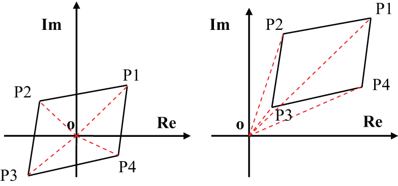
Edges and zero exclusion method.
The algorithm of finding stability is described in Figure 2. The input parameters include the feed rate, the cutting coefficients, the dynamics at the tool tip, and so on. Then, the algorithm sweeps the depths of cut and chatter frequencies at each spindle speed. After the edges are formed, the stability of edges at each condition is checked through the proposed zero exclusion method. If the cutting operation is identified to be stable at current cutting depth, the algorithm will try the next depth of cut. Otherwise, the first depth of cut causing the unstable machining is identified as the border between the stable and unstable regions at that specific spindle speed. Furthermore, the algorithm continues to sweep the spindle speed range to find the critical depth of cut in all of the conditions. Assembling all of these individual points in one diagram will form the stability lobes. As the proposed algorithm sweeps the spindle speed and depth of cut range, it may take a lot of simulation time.

Algorithm for robust chatter stability.
The cutting coefficients and natural frequency are the two parameters which are considered to be changed in this robust chatter model. The robust stability model will predict a different stability boundary than the conventional analytical chatter stability model with variations taken into account. Actual chatter conditions at different depths of cut and spindle speeds can be detected and compared with the simulated lobes to verify the model.
Experiments
This study utilized a three-axis computer numerical controlled (CNC) milling machine tool that implements an electric spindle with air bearings to provide a maximum speed of 120,000 r/min. Figure 3 illustrates the experimental setup.

Experiment setup.
The goal is to verify robust stability by introducing uncertainty in the cutting parameters, namely, the natural frequencies and the cutting coefficients. The system dynamics were determined through mathematical coupling of substructures using the receptance coupling (RC) method, and the cutting coefficients were identified for a given workpiece and cutting tool material. Chatter tests were performed to simulate chatter conditions for comparison with predicted stability lobes.
Tool tip dynamics
Chatter stability mainly depends on the tool tip dynamics, which in turn are highly influenced by the spindle dynamics, especially at high rotational speeds.20,21 These parameters must be found experimentally for the milling system for accurate chatter prediction. For micro end mills, a combination of experimental modal analysis (EMA) and RC, are employed to identify tool tip dynamics.
EMA is an experimental method to acquire dynamic parameters of mechanical systems. Usually, impact hammers are used to deliver initial exciting forces to the system, and the response is measured through sensors. For the dynamics of the micro milling tools, impact hammer testing cannot be applied directly to measure tool tip response due to the fragility of micro milling tools. RC can be used to combine EMA results of the spindle and a finite element (FE) model of the micro tool to obtain the dynamics of the tool tip. For the chatter tests, the dynamics for a two fluted, tungsten carbide 500 µm diameter end mill, with a 35-mm overhang length and a 3-mm shank diameter needs to be obtained first. To apply the RC method, the end mill is modeled into two parts as shown in Figure 4, a lower substructure A containing the cutting portion and an upper part, substructure B.

Receptance coupling modeling of micro end mill.
The dynamics of substructure B are identified using a blank tungsten carbide cylinder with a 15-mm overhang with a miniature impact hammer (PCB208A03) and accelerometer (Kistler 8778A500).
The dynamics of the cutting tool, as well as substructure A, can be obtained in free-free boundary conditions using FE analysis. The bottom 20-mm portion of the cutting tool is modeled as three sections using Timoshenko beam theory. The material parameters for tungsten carbide end mills used in the FE analysis are as follows: Young’s Modulus = 580 GPa, density = 14,300 kg/m3, Poisson’s ratio = 0.28, and damping ratio = 0.01. Then dynamics are coupled mathematically using compatibility conditions of the joint. The dominant modal parameters of the tool tip are summarized in Table 1. The tool tip dynamics were assumed to be the same in both the X and Y directions due to the symmetrical shape of the cylindrical micro end mill.
Dynamic parameters at the tool tip.

It can be seen from Table 1 that mode 4 shows the most dominant mode at the tool tip for each direction. Stability lobes are plotted by sweeping a range of chatter frequencies around all dominant modes of the milling system.
Cutting tests to acquire cutting coefficients
The cutting coefficients reflect the contributions of the workpiece material and cutting conditions to cutting forces, which must be found experimentally. Cutting coefficient tests were performed on a high-speed CNC machine (Haas Micro) at different feed rates to acquire the cutting forces at stable cutting conditions. The coefficients were determined for two aluminum alloys Al 2024 with a two fluted, 500 µm diameter carbide end mill with a 3-mm diameter shank. A miniature table dynamometer (Kistler 9317B) was used to measure cutting forces. The data were acquired for 100,000 samples per second using a data acquisition system (NI 9233). And anti-aliasing filters were used during the data acquisition. An acoustic emission sensor was used to ensure that chatter did not occur during the cutting coefficient experiments. Cutting conditions were set at a constant spindle speed of 80,000 r/min with full immersion conditions.
Chip thicknesses in micro milling process vary with both feed rate and immersion angle. A plowing effect can be observed during the cutting operation if the feed rate is below a critical value. For this study, experimental force measurements were curve fitted using the linear cutting force model in equation (11)
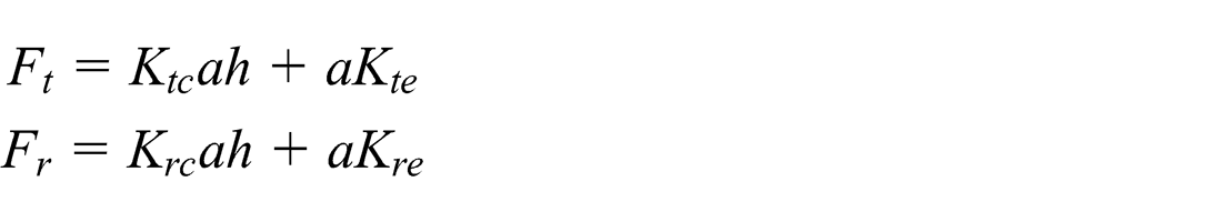
where
Mechanistic coefficients.

Results and discussions
Experimental results
The simulated chatter tests were performed over a range of cutting depths and spindle speeds. Chatter tests were performed with the workpiece Al 2024. Figure 5 outlines the predicted stability lobes and the stable and unstable points tested. Lobe predicted using conventional chatter stability modes was also plotted to compare with the robust stability model. All lobes were plotted over the same spindle speed and cutting depth range as the chatter tests, and iterated by sweeping a frequency range from 10 Hz to 4000 Hz, which can cover all the dominant frequencies of the tool and spindle. The occurrence of chatter was determined for each spindle speed and cutting depth combination tested based on the acoustic emission sensor data acquired in the frequency domain. Due to the high bandwidth of acoustic emission sensor, high frequency chatter signals can be easily detected. When chatter is detected, a prominent peak occurs.22,23 It can be seen from Figure 5 that the experimental chatter tests show a good correlation to the predicted robust stability lobes with most of chatter free points below the robust boundary. It can be observed that many of the unstable points that were detected below the lobes were predicted by the analytical chatter stability model. This indicates that the robust method gives a more conservative prediction than conventional method, which is the main advantage of predicting chatter stability using the robust method. As system parameters may fall anywhere within a given range, the analytical chatter stability model may shift and not adequately predict a suitable stable cutting regime. Robust stability accounts for all the range the parameters vary, whereas the conventional stability lobes account only for a constant value of the parameters.

Comparison of robust stability lobe with experimental test points.
If parameters change during micro milling operations, the analytical chatter stability lobes may shift accordingly. A robust stability method will give a conservative prediction, which can assure the stability. Robust stability is based upon the analytical chatter stability model, and therefore, the lobes predicted are related to how the analytical chatter stability model lobes shift. Robust stability does not predict a new set of lobes; it only allows the analytical chatter stability model to analytically account for uncertainties.
Discussion
From conventional analytical chatter method, chatter stability lobes shifts can be observed as the individual system parameters are changed. A major aspect of robustly predicted lobes is the apparent shift that is made from the analytical model by accounting for uncertainties. Most of the current chatter theories explain that natural frequency is related to spindle speed, and any change in the natural frequency will tend to shift the horizontal locations of the stability lobes. Changing cutting coefficients will mainly affect the cutting depth, while changing the damping ratio will vary the magnitude of the stability peaks. For parameters that lie within a given uncertainty interval, these stability lobe shifts can be observed if analytical chatter stability is plotted at the maximum and minimum extremes.
The effects of robust stability in comparison to analytical chatter stability can be simulated for a given varying parameter. If parameters vary during a micro milling operation, analytical chatter stability may not inevitably produce a precise stability limit since the model uses constant parameters, whereas robust stability takes parameter uncertainties into account. It also can be observed that when robust chatter stability lobes take into account parameter uncertainty, it predicts the most conservative stability lobes. Edge theorem can be used to consider any two parameters and not just the natural frequency and cutting coefficient. Currently, the robust chatter stability model is already an accurate and well-used model which can account for parameter variations and can enhance the practicality of analytical chatter stability model.
Compared to other methods for predicting parameter uncertainty, robust control method is easy to apply and needs much less data. However, in actual micro milling process, other dynamic effects such as thermal effects, stiffness, and tool wear would also change. So the number of polynomial equations and the computational time will increase with more parameters. Accordingly, there are also many difficulties associated with modeling different sources of uncertainty and identifying these variations experimentally.
Conclusion
Many uncertainties occur during actual machining operations and affect the regenerative chatter. Accurate chatter prediction is crucial in micro milling operations in order to improve tool life, dimensional accuracy, and productivity. The regenerative chatter stability is strongly influenced by the dynamics of milling system, which are highly influenced by spindle, tool, cutting coefficients, and so on. The conventional mathematical formulations characterizing chatter vibrations assume that the machining parameters are constant. Variations in these parameters have a major effect in predicting chatter stability lobes essentially. The experiments were performed to predict parameter uncertainties in order to evaluate the effectiveness of a robust method. Robust control theory is a useful method to account for varying parameters in real machining systems.
A robust stability model for 2DOF micro milling systems was presented by extending analytical chatter stability using robust theorem and zero exclusion method. In this work, only two changing parameters were considered as the complexity of the formulation grows with more parameters considered. Dynamics were found through mathematical coupling of substructures using the RC method, and cutting coefficients were determined through optimizing curve fitting on measured cutting forces. The parameters and variations were accounted for and implemented in the robust model, and the stability lobes are predicted using the proposed robust formulation. This result was compared to lobes predicted by the conventional analytical chatter stability method and tested chatter conditions.
The analytical chatter stability model requires constant parameters, which can shift the predicted lobes with parameters changed. The robust formulation may not capture all stable points; however, it enables us to conservatively predict chatter stability for a micro milling system with varying parameters. In general, robust stability traces the lowest points predicted by the stability lobes. Robust stability can predict a boundary below which stability is guaranteed if uncertainty range for the parameters is provided. In summary, the analytical chatter stability model for micro milling operations was successfully extending into a robust stability formulation accounting for parameters uncertainty.
Footnotes
Academic Editor: Pedro AR Rosa
Declaration of conflicting interests
The authors declare that there is no conflict of interests regarding the publication of this article.
Funding
This project is supported by National Natural Science Foundation of China (grant no. 51305286), Suzhou Science and Technology Projects (SYG201244), Jiangsu Natural Science Foundation (BK2011314), and also sponsored by Qing Lan Project of Jiangsu Province.