
Abstract
Brain–computer interface provides a new communication channel to control external device by directly translating the brain activity into commands. In this article, as the foundation of electroencephalogram-based robot-assisted upper limb rehabilitation therapy, we report on designing a brain–computer interface–based online robot control system which is made up of electroencephalogram amplifier, acquisition and experimental platform, feature extraction algorithm based on discrete wavelet transform and autoregressive model, linear discriminant analysis classifier, robot control board, and Rhino XR-1 robot. The performance of the system has been tested by 30 participants, and satisfactory results are achieved with an average error rate of 8.5%. Moreover, the advantage of the feature extraction method was further validated by the Graz data set for brain–computer interface competition 2003, and an error rate of 10.0% was obtained. This method provides a useful way for the research of brain–computer interface system and lays a foundation for brain–computer interface–based robotic upper extremity rehabilitation therapy.
Introduction
Brain–computer interface (BCI) technology can directly transfer the activity of the brain into commands to control external devices. Now, BCI research is exploring many applications in different fields. An electroencephalogram (EEG)-based BCI system was developed for robotic interaction with environment, in which navigation and transport of objects are realized. 1 Fraunhofer-Gesellschaft Institute developed a brain-actuated wheelchair and the subject could guide the wheelchair by a BCI. 2 In Geng et al., 3 an asynchronous BCI system was designed to control a robot in the home. A shared control system was presented to drive an intelligent wheelchair using EEG signals in Vanacker et al. 4 This study demonstrates that the shared control system can improve the controlling performance. Although many different medical robots have been designed5–9 and provide effective tools for many stroke patients, there is no direct communication between the patient’s motor volitional thinking and the rehabilitation system. In recent years, noninvasive BCI has also been shown to have a beneficial effect in stroke rehabilitation. In Broetz et al., 10 the BCI was utilized to help stroke patients to perform recovery exercises. This research adopted the EEG and magnetic brain activity (magnetoencephalography (MEG)) to control the robot to stretch the subject’s affected upper limb and shows that the combination of BCI with goal-directed mechanism can accelerate the rehabilitation training.
Online feature extraction of the EEG is one of the challenges in designing BCI system. At present, several feature extraction methods, such as Fourier transform (FFT), 11 short-time Fourier transform (SFT), 12 autoregressive (AR) model,13–15 adaptive autoregressive (AAR)16–18 parameters, and wavelet transform (WT), 19 are commonly used in this field. The AR model or FFT model cannot capture the transient features in a given signal, and the non-stationary information is ignored in the AR parameters or transformed Fourier coefficients. SFT localizes the time and frequency information by a uniform time window. The WT adjusts the window size according to the frequency, and it is quite powerful in selecting features from the time–frequency domain.
In this article, discrete wavelet transform (DWT) in conjunction with AR are proposed to extract features of hand movement imagination. In addition, as the foundation of BCI-based robotic rehabilitation therapy, an online robot control system is designed, including hardware, software, and feature extraction algorithm based on DWT and AR. A large number of experiments have been conducted to validate the effectiveness of BCI-based system. Moreover, Graz data set is utilized to evaluate the performance of the pattern recognition algorithm, and the results demonstrate that it can effectively improve the classification performance in motor imagery EEG-based BCI systems.
System design
System overview
The robot control system mainly consists of EEG electrodes, EEG amplifier, PC, robot control board, and Rhino XR-1 robot. First, EEG amplifier acquires the signal and sends it to PC in real time via the USB interface. Second, the feature extraction and classification algorithm for mental imagination of hand movement figures out the classification result. Finally, the robot control board controls the robot according to the classification result. The composition of the entire system is shown in Figure 1.

The motor imagery EEG-based robot control system.
EEG data acquisition equipment design
Figure 2 presents the overall design of the USB EEG amplifier including Ag/AgCl electrodes, shielded twisted pair, preamp, high-pass filter, main amplifier, isolation, notch filter, low-pass filter, secondary amplifier, analog-to-digital (A/D) converter with 16-bit resolution, and micro control unit (MCU). First, the instrumentation amplifier of AD8221BR is selected to amplify the EEG signal. AD8221BR has the industry’s highest common-mode rejection ratio (CMRR) over frequency in its class. Second, an active high-pass filter is utilized to remove direct current (DC) voltage offset, and the signals were amplified about 83 times in the main amplifier stage. Active filter and amplification circuit use the high-precision amplifier of AD8627. Third, the signal is isolated by ISO124. Finally, a low-pass active filter is used to remove the high-frequency noise. After that, the signal is sent to the 16-bit A/D converter (ADS7805). Detailed design of the similar circuit can be seen in Xu et al. 20

EEG amplifier.
The microcontroller (C8051F340) reads the digitized EEG from the A/D converter and sends it to PC via the USB interface. It has the following properties:
It has a high-speed 8051 µC core with 48 MIPS throughput.
It integrates a USB 2.0 function controller.
It has 64 KB flash, 256 bytes data RAM, and 4 KB XRAM.
To ensure minimum distortion of the sampled EEG signals, the latest developments in EEG acquisition and analog integrated circuit are considered to design the schematic and print circuit board. In acquiring the steady-state visually evoked potential (SSVEP) and motor imagery EEG, the EEG amplifier shows its stability and reliability. In testing the EEG amplifier, a 15-Hz square-wave signal or sine-wave signal from function generator was first divided down to about 10 µV and then fed to it. Raw EEG signals were obtained from the EEG amplifier via USB interface using high-level data acquisition functions (OpenDevice(), InitDeviceAD(), ReleaseDeviceAD(), and CloseDevice()) and saved to PC in the form of binary for further analysis.
Pattern recognition algorithm for motor imagery EEG
Owing to the variable window size, wavelets can get an optimal time–frequency resolution in all the frequency bands. In processing the non-stationary EEG signals, the WT is better than the conventional FFT or AR. The WT decomposes a signal into a set of functions obtained by shifting and dilating one single function called mother wavelet.21,22 Continuous wavelet transform (CWT) can be obtained by
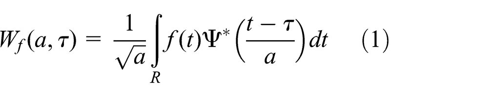
where
Figure 3 shows the CWT of EEG signals of C3 electrode location during left motor imagery and right motor imagery. Obviously, the CWT generates infinite coefficients and it is time-consuming to compute.
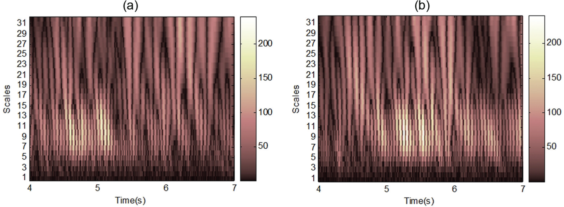
CWT of EEG signals taken for the C3 electrode location during (a) left motor imagery and (b) right motor imagery.
However, the DWT realized by a recursive filter and an inverse filter produces only the same number of coefficients as the number of samples. Full information of the EEG signals is expressed by wavelet coefficients. Figures 4 and 5 show the approximations (A1–A3) and details (D1–D3) of C4 channel during left and right motor imagination, respectively. These approximations and details are reconstructed from the wavelet coefficients.
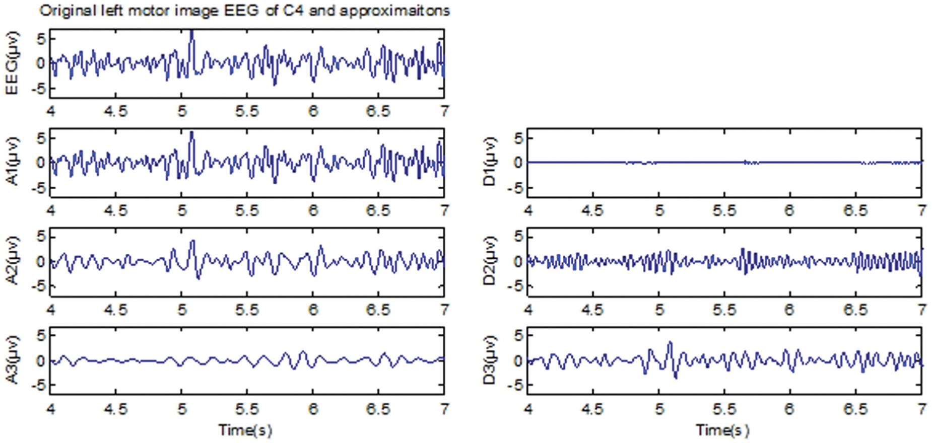
Approximations and details of Daubechies 10 wavelet on EEG signals taken for the C4 channel during left motor imagination.
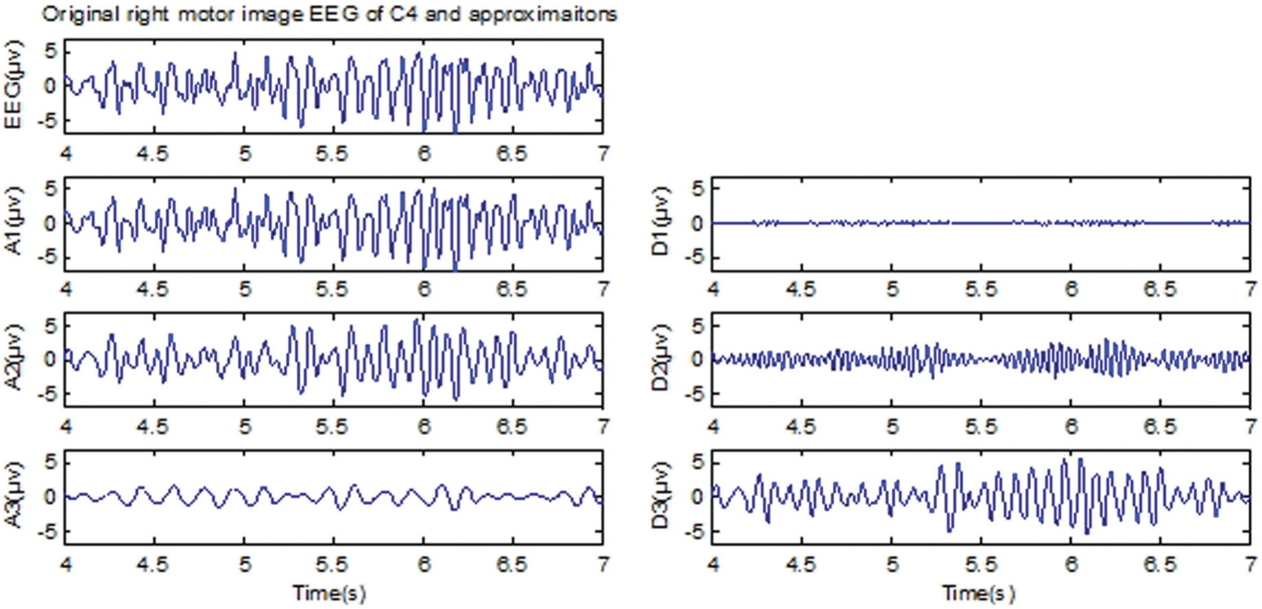
Approximations and details of Daubechies 10 wavelet on EEG signals taken for the C4 channel during right motor imagination.
Level of 3 and the wavelet of Daubechies order 10 were used to decompose the EEG signal into the details D1–D3 and approximation A3. Table 1 shows the ranges of different frequency bands. Wavelet coefficients of the component D3 (with the mu rhythm) and D2 (within the beta rhythm) were chosen for further analysis. The mean of the wavelet coefficients, standard deviation of the wavelet coefficients, and average power of the wavelet coefficients were used as features. 23
Frequencies corresponding to different levels of deposition for Daubechies order 10 wavelet with a sample rate of 128 Hz.

In addition, the six-order AR coefficients are also used as feature for each channel. Linear discriminant analysis (LDA) is chosen as the classifier,24,25 which can ensure the maximal separability by maximizing the ratio of between-class variance to the within-class variance.
Control scheme
Figure 6 shows the control scheme of the motor imagery–based robot control system. BCI research platform is utilized to realize the upper layer. The main function of the upper layer is providing the control board with commands for robot arm movement via USB interface. Our BCI research platform can be divided into three components: recording module, training module, and testing module. Recording module records the data of multiple experiments and saves it to the file of “train.bin” in binary form. Training labels are saved in the file of “true labels of train.bin.” Training module is a key part of the system. First, eigenvectors of the training data are extracted based on statistical characteristics of wavelet coefficients and the six-order AR model coefficients. Next, the weight matrix and bias of the linear LDA classifier are computed so as to be used in the testing module. Figure 7 shows the flow chart of the training module.

A scheme for the EEG-based robot control system.

Flow chart of the training module.
The main function of testing module is recording the data of experiment and classifying the feature vector. (The weight matrix and bias parameter of the LDA classifier have been calculated in training module.) The classification result will be transferred to the robot control board through USB interface. Then, the board controls the robot in accordance with the order. The arm of the robot moves upward at an angle of 60°, when the classification result is imaging left-hand movement. Conversely, the arm of the robot moves downward at an angle of negative 60°, when the classification result is imaging right-hand movement. Next, single-trial motor imagery EEG data are saved to the file of “test.bin” in binary form. Every trial’s classification result is saved to the file of “classification results.bin” and true label is saved to the file of true labels of test.bin. When all runs of experiment are finished, the classification accuracy of single subject is calculated based on the above two files. Figure 8 shows the flow chart of the testing module.
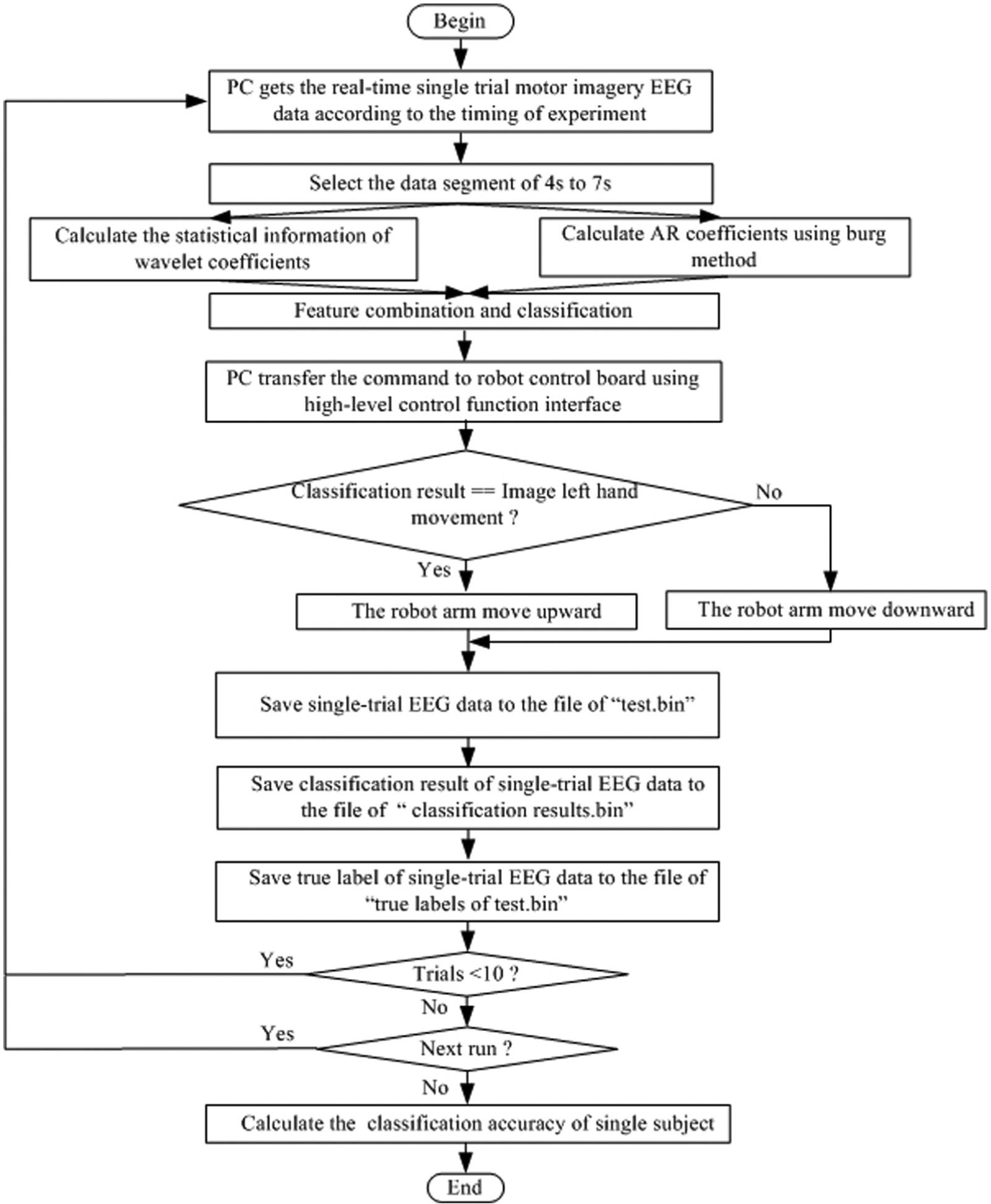
Flow chart of the testing module.
The lower layer of the motor imagery EEG-based robot control system is implemented on the control board and obtains the commands from PC via USB interface. The hardware of the robot control system is constituted by control board and power amplifier board. These two boards are isolated by optocouplers for the purpose of reducing electrical interference. The lower layer firmware is given by control algorithms running on the microprocessor. The actuator control system operates the robot motors according to the commands from PC and the feedback sensors.
Experimental procedures
Figure 9 demonstrates the operational procedures of the experiment. The first 2 s was quite. At t = 2 s, a cross “+” was shown to point out the start of the experiment. Then, at t = 3 s, an arrow (left or right randomly) was shown to ask the subject to perform mental imagination of left- or right-hand movement according to the arrow. Next, the robot was controlled by PC via USB interface in accordance with the online classification result. The arm of the robot moves upward at an angle of 60°, when the classification result is left-hand movement imagination. Conversely, the arm of the robot moves downward at an angle of negative 60°, when the classification result is right-hand movement imagination.
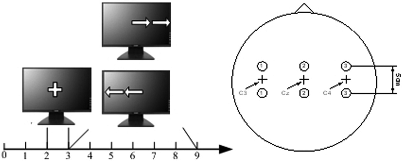
Timing scheme (left) and electrode positions (right).
Motor imagery EEG signals were recorded using our EEG amplifier. Differential signals of C3 and C4 (Figure 9, right) channels were measured. EEG signals were sampled at 128 Hz and band-pass filtered (0.5–30 Hz).
The training experiment consists of four to five runs with 10 trials each, and the testing experiment consists of 20–30 trials. A total of 30 subjects aged from 21 to 26 years are from Southeast University in Nanjing, China. This research had been approved by the local committee.
Experiment results and discussion
Channels C3 and C4 were utilized to extract features of hand movement imagination. For the purpose of obtaining the segment that has the obvious difference of the two mental imagination tasks, the EEG data among t = 4 s and 7 s were adopted. For each channel, six statistical features of the wavelet coefficients and six AR coefficients were obtained, giving a total of 24 features for a mental imagination task. Finally, these features were used as inputs for LDA classifier. Performance of the system has been tested by 30 different participants, and the average error rate is 8.5%. Table 2 shows the online classification rate of some of the subjects.
Online recognition rate of six participants.

Figures 10 and 11 are the pictures of subject S4 using motor imagery EEG to control the robot. The initial status of the robot arm is in horizontal position. When the subject images left-hand movement, the arm of the robot moves upward at an angle of 60°. Conversely, when the subject images right-hand movement, the arm of the robot moves downward at an angle of negative 60°.
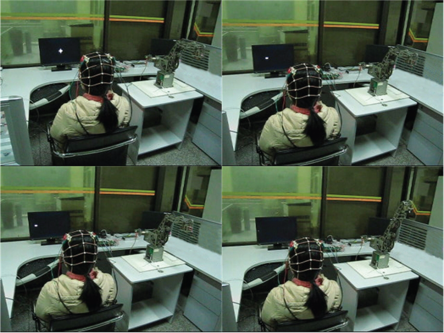
Control the robot using motor imagery EEG of left-hand movement. An arrow moves left on the monitor, and the subject images left-hand movement. Online pattern recognition algorithm outputs the classification result based on the features of motor imagery EEG. Finally, PC sends the command to the control board and the robot arm moves upward at an angle of 60°.
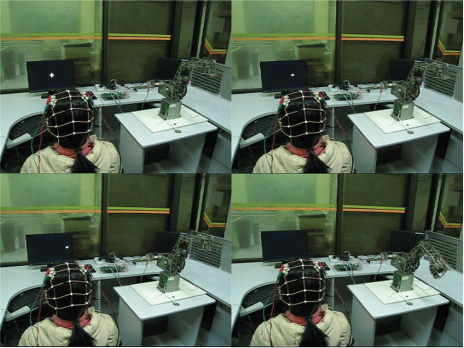
Control the robot using motor imagery EEG of right-hand movement. An arrow moves right on the monitor, and the subject images right-hand movement. Online pattern recognition algorithm outputs the classification result based on the features of motor imagery EEG. Finally, PC sends the command to the control board and the robot arm moves downward at an angle of negative 60°.
In addition, the Graz data set 26 was used to evaluate the proposed features for classifying the patterns of hand movement imagination tasks. This data set was made up of seven runs with 40 trials each. Among the total 280 trials, half of them were utilized to train the LDA classifier. Since the true labels of the rest trials are now available, we can apply them to validate the performance of our method to recognize motor imagery EEG patterns. Table 3 illustrates the classification result using different classifiers (neural network (NN), support vector machine (SVM), and LDA) to classify Graz data set on the basis of proposed hand movement imagination features. The NN with three layers and the SVM with polynomial kernel were adopted. The layers of the NN, input layer, hidden layer, and output layer, have the nodes of 24, 19, and 2, respectively. We apply the back-propagation algorithm to train the NN. Table 3 shows that LDA with the proposed features gets the satisfactory results on the Graz data set with an error rate of 10.00%.
Recognition rate of the proposed method with different classifiers on the Graz BCI data set.

NN: neural network; SVM: support vector machine; LDA: linear discriminant analysis.
Table 4 demonstrates the classification rate of the proposed method and the BCI competition 2003 winning methods 27 on this Graz data set. It can be seen from the table that LDA classifier gets the recognition rate of 90% using the proposed EEG features, which outperforms the first winner of the BCI competition 2003. Furthermore, the results indicate that the feature extraction method of DWT in conjunction with AR can get more information from the mental imagination EEG signals of hand movement. Additionally, a maximum recognition rate of 92.1% is obtained when the windows of 384 samples with a shift of one sample were used.
Recognition rate of the proposed feature extraction and classification method and the BCI competition 2003 wining methods on the Graz BCI data set.

BCI: brain–computer interface.
In the experiments on a PC with main frequency of 2.66 GHz, it takes only 7.4 ms to recognize the mental imagination pattern of hand movement from EEG signals. Therefore, the proposed feature extraction and classification method is not time-consuming. The main disadvantage of the proposed method is that selecting the order of AR is difficult.
Conclusion
In this article, a BCI-based online robot control system is realized for the research and application of BCI technology. The experiment results show the effectiveness and reliability of the whole system. Feature extraction and classification algorithm for hand movement imagination was implemented on our BCI research platform. Average online classification accuracy of 91.5% is achieved. Mental imagination of hand movement was detected to control the robot. Furthermore, Graz data set was utilized to evaluate the performance of the proposed features, and an error rate of 10% was achieved. Therefore, a new idea is provided for EEG feature extraction, and it also brings convenience for the research of online BCI technology.
Footnotes
Academic Editor: Zhuming Bi
Declaration of conflicting interests
The authors declare no conflict of interest.
Funding
This work was supported by the Natural Science Foundation of China (No. 61325018, No. 61272379, No. 61104206, No. 61403080, No. 61105048, No. 61305095, No. 61075068, and No. 61302131), Natural Science Foundation of Jiangsu Province (No. BK20141284), National High Technology Research and Development Program of China (No. 2013AA013703), Key Technology R&D Program of the Ministry of Science and Technology of Jiangsu Province (No. BE2012740), RD Project of China Southern Power Grid (K-GX2014-208, K-GX2014-062-49), the Open Fund of Jiangsu Province Key Laboratory for Remote Measuring and Control (No. YCCK201005 and No. YCCK201205), and RD Projects of Guangdong Province and Guangzhou City.