
Abstract
The goal of our research is to develop an assistive controller for robotic rehabilitation of the upper extremity after stroke. The controller is used to provide robotic assistance to participants to help them to track a desired motion trajectory required for the rehabilitation task in an accurate and concentrated manner. This rehabilitation task is designed to ensure concentrated repetitive motion that requires cognitive processing. Experimental results on unimpaired participants are presented to demonstrate the effectiveness and feasibility of the proposed controller.
Introduction
Stroke is a highly prevalent condition especially among the elderly that results in high costs to the individual and society (Matchar, D.B. & Duncan, P.W., 1994). According to the American Heart Association, in the U.S., approximately 700,000 people suffer a first or recurrent stroke each year (American Heart Association, 2006). It is a leading cause of disability, commonly involving deficits of motor function.
Recent clinical results have indicated that movement assisted therapy can have a significant beneficial impact on a large segment of the population affected by stroke or other motor deficit disorders. Experimental evidence suggests that intensive movement training of new motor tasks is required to induce long-term brain plasticity. The availability of movement training techniques, however, is limited by the amount of costly therapist's time they involve and the ability of the therapist to provide controlled, quantifiable and repeatable assistance to arm movement. Consequently, robot assisted rehabilitation that can quantitatively monitor and adapt to patient's progress, ensure consistency during rehabilitation may provide a solution to these problems.
In the last few years, robot-assisted rehabilitation for physical rehabilitation of the stroke patients has been an active research area to assist, monitor, and quantify rehabilitation therapies (Krebs 2004, Lum 2006, Kahn 2006, Loureiro 2003). These robotic devices are used to recover arm movement after stroke, which provide opportunities for repetitive movement exercise and more standardized delivery of therapy with the potential of enhancing quantification of the therapeutic process. The first robotic assistive device used as a therapeutic tool, the MIT Manus (Krebs 2003, 2004) uses impedance controller to provide assistance to move patient's arm to the target position in an active assisted mode, where patients can visually see their movement and target location. In (Krebs 2004) they expand the capabilities of MIT Manus to include motion in a three-dimensional workspace to rehabilitate other muscle groups and limb segments than shoulder and elbow. The Mirror Image Movement Enabler (MIME) and the Assisted Rehabilitation and Measurement (ARM) Guide, expanded the investigations of therapeutic applications of robots into the chronic stroke population. MIME uses a PUMA 560 manipulator to provide assistance to move the subject's arm with a pre-programmed position trajectory using Proportional-Integral-Derivative (PID) controller (Lum 2006). ARM Guide is capable of generating both horizontal and vertical motion, and giving resistance and support to the patient (Kahn 2006). The GENTLE/s (Loureiro 2003) is a haptic robot used to provide assistance to patients to move to the target positions along with a predefined path using admittance control. The subject's movement trajectory is represented in the virtual environment.
The promising results of the above-mentioned rehabilitation robotic systems indicate that robots could be used as effective rehabilitation tools. Current theories of stroke rehabilitation point towards paradigms of intense and repetitive use of the affected limb as a means for motor program reorganization. However, it has also been demonstrated in (Carey 2005) that repetitive execution of simple motor tasks may not be as effective as execution of more complex motor tasks that involve in-depth cognitive processing. Precision-demanding tasks that challenge motor learning processes create richer conditions for change in the brain reorganization on rats (Black 1990, Kleim 2002), primates (Plautz 2000, Nudo 1996) and human (Pascual-Leone 1995). It was shown that movement tracking training that requires cognitive processing achieved greater gains in performance than that of movement training that did not require cognitive processing (Carey 2005). Additionally, it was shown that finger movement tracking training produced greater gains in the range of motion and tracking accuracy compared to finger movement training that required no temporospatial processing (Carey 2006). Thus, it would be useful if a tracking movement training method can be developed, where the patients not only make repetitive movement but also pay attention to tracking accuracy. However, in such a tracking task, patients may not be able to track the desired motion because of their impairments. Thus, a rehabilitation robotic system can be designed to provide assistance to the patient to track the desired motion accurately based on his/her performance.
In this paper, we present a controller to be used to provide robotic assistance as and when needed to the participants to complete an upper arm rehabilitation task. This task is designed to impart movement training that requires cognitive processing. Note that the presented assistive controller is not specific to a given rehabilitaion robotic system but can be integrated with any previously proposed rehabilitation systems. However, in order to demonstrate the efficacy of the proposed assistive controller, we needed to develop a rehabilitation robotic system, which is also presented in the paper.
This paper is organized as follows. It first presents the proposed rehabilitation robotic system in Section 2. The methodology section (Section 3) includes task description, controller design, and decision logic of robotic assistance. Experiments and results are presented in Section 4. Section 5 discusses the potential contributions of this work and possible future research directions.
The Rehabilitation Robotic System
A PUMA 560 robotic manipulator is used as the main hardware platform in this work. The manipulator is augmented with a force-torque sensor and a hand attachment device (Fig. 1).

Participant Arm attached to Robot
The PUMA 560 is a 6 degrees-of-freedom (DOF) device consisting of six revolute joints (PUMA web site). In order to record the force and torque applied by the human, an ATI Gamma force/torque sensor is used. The robot is interfaced with Matlab/Real-time Workshop to allow fast and easy system development. The force values recorded from the force/torque sensor are obtained using a National Instruments PCI-6031E data acquisition card with a sampling time of 0.001 seconds. The joint angles of the robot are measured using encoder with a sample time of 0.001 seconds from a Measurement Computing PCI-QUAD04 card. The torque output to the robot is provided by a Measurement Computing PCIM-DDA06/16 card with the same sample time. A computer monitor is placed in front of the subject to provide visual feedback about his/her motion trajectory during the execution of the task.
Hand attachment device
Since in this work we are primarily interested in effecting assistance to the upper arm, we design a hand attachment device where the participant's arm is strapped into a splint that restricts wrist and hand movement. The PUMA 560 is attached to that splint to provide assistance to the upper arm movement using the assistive controller (Fig. 1). Forearm padded aluminum splint (from MooreMedical), which ensures the participant's comfort, is used as a splint in this device. We further design a steel plate with proper grooves that hold two small flat-faced electromagnets (from Magnetool Inc.) that are screwed on it. This plate is also screwed with the force-torque sensor, which provides a rigid connection with the robot. We attach a light-weight steel plate under the splint, which is then attached to the electromagnets of the plate. These electromagnets are rated for continuous duty cycle (100% duty cycle), i.e., they can run continuously at normal room temperature. Pull ratings of these magnets are 40lb. We have used two electromagnets to have a larger pulling force to keep the splint attached to the hand attachment device. An automatic release (AU) rectifier controller (Magnetool Inc.) has been used to provide a quick, clean release of these electromagnets. A push button, which has been connected to the AU Rectifier Controller, is used to magnetize and demagnetize the electromagnets when the participant wants to remove the hand attachment device from the robotic manipulator in a safe and quick manner.
Safety discussion about both the use of PUMA 560 Robotic Manipulator and Hand Attachment Device
Ensuring safety of the participant is a very important issue when designing a rehabilitation robotic system. Thus, in case of emergency situations, therapist can press emergency button. The patient and/or the therapist can quickly release the patient's arm from the PUMA 560 by using the quick-release hand attachment device (as described above) to deal with any physical safety related events. In order to release the participant's arm from the robot, the push button is used. When the push button is pressed electromagnets are demagnetized instantaneously and the participant is free to remove the splint from the robot. This push button can also be operated by a therapist. Additionally, we have covered the corner of the arm device with a foam self stick tape in order to avoid sharp surface.
Methodology
The objectives of the current work is to: i) design an upper arm movement rehabilitation task that requires cognitive processing as well as could contribute to a variety of functional daily living activities, and ii) design a controller to provide robotic assistance to help participants to perform the above movement rehabilitation task. In what follows we present the basic design of the task and the assistive controller.
Task Design
Let us first briefly review the task design of some well-known robotic rehabilitation systems. MIT Manus uses impedance controller to provide assistance to move patient's arm to the target position in an active assisted mode, where patients can visually see their movement and target location (Krebs 2003, 2004). MIME provides assistance to move the participant's arm with a pre-programmed position trajectory using proportional-integral-derivative (PID) controller (Burgar 2000, Lum 2006). The participant is asked to maintain a specified off-axis force while they are trying to reach toward a goal position using ARM Guide (Kahn 2006). The GENTLE/s provides assistance to patients to move to the target positions along with a predefined path using admittance control. The participant's movement trajectory is represented in the virtual environment in (Loureiro 2003). The therapy tasks designed for the rehabilitation robotic devices require predominantly shoulder motion or elbow motion, or some of them require the combination of both shoulder and elbow motion.
We choose a reaching task that is commonly used for rehabilitation of upper extremity after stroke. In this task, the participants are asked to move their arms in the forward direction to reach a desired point in space and then bring it back to the starting position repeatedly within a specified time. In other words, they have to follow a desired position trajectory. The reaching task designed in here requires combination of the shoulder and elbow which could increase the active range of motion (AROM) in shoulder and elbow in preparation of later functional reaching activities in rehabilitation. The allowable motion is restricted only to the direction of the task. For example, if the task requires the participants to move their arms in the Y-direction, then they will not be able to move their arms in X or Z directions. However, they can move their arms in the Y-direction at a velocity that could be the same, higher or lower than the desired velocity. The idea here is to improve the ability of participant's arm movement in one direction at a time by helping them to improve their speed of movement. Improving the speed of movement for such tasks is an important criterion to measure the success of a therapy. For example, in Constraint Induced Movement Therapy (CIMT) (Taub 1999) during the performance of the wipe table task, participants are required to complete as many back and forth motion as possible in a certain amount of time across the table and back between the two targets. The number of times of the completed movement in a certain amount of time is used as a metric to evaluate the participants' progress. If participants can improve their speed of movement, the metric described above will capture this progress. In this work, we constrain the motion of the arm in the horizontal plane and in one direction (along the Y-axis). Although, in this work the motion of the arm is constrained in the horizontal plane in one direction (along the Y-axis), it could also be designed for other directions (e.g., X-axis) or combination of directions (e.g., XY-axes) based on task requirements (only shoulder or elbow motion or the combination of shoulder and elbow motion).
In order to include cognitive processing within this reaching task, we ask the participants to follow a visually presented desired motion trajectory that is likely to command their concentration. The participants receive visual feedback of both their actual position and the desired position trajectories on a computer screen, which is placed in front of them. They are asked to pay attention to tracking the desired position trajectory as accurately as possible, which keeps them focused on the task. The visual feedback is used not only to inform the participants of how closely they are tracking the desired motion but also as a motivational factor to keep them focused on the task. The tip of the position trajectory that the participant is required to follow represents the velocity of the task trajectory.
The task presented here incorporates cognitive processing by asking the participants to follow the tip of the visually presented trajectory. The tip of the trajectory represents the current desired velocity. By asking the participant to follow the tip makes him/her focused on the task. This task is different from other tasks that have been used in the context of robotic rehabilitation in that here we are interested in improving the speed of motion in one direction at a time using visual feedback, which could be useful in a number of therapy tasks.
Controller Design
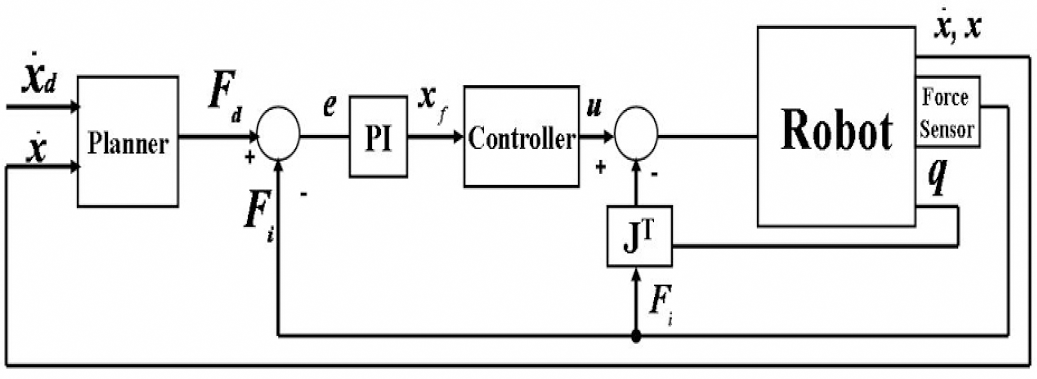
The controller designed in this work is responsible for providing robotic assistance to a participant to complete the movement tracking task in an accurate manner. The existing robotic rehabilitation systems operate in robot task-space to provide robotic assistance to the patients to follow a desired trajectory to complete a rehabilitation task (Krebs 2004, Lum 2006, Kahn 2006). Recently, a human-arm joint impedance controller is proposed, which operates in joint-space, to provide assistance to subjects to follow desired joint angle trajectory (Culmer 2005) specified for each individual joint (e.g., elbow joint). It is still not clear, however, whether the assistance in the task-space or in the joint-space will likely to have the best results for rehabilitation purposes. In this work, we design a controller that is responsible for providing the robotic assistance to subjects to complete a rehabilitation task in task-space. In this controller, an outer force feedback loop is designed around an inner position loop (Fig. 2). The tracking of the reference trajectory is guaranteed by the inner motion control (Sciavicco 1996). The desired force, which is given as a force reference to the controller, is computed by a planner. The proposed controller is similar to an impedance controller; however it allows specifying the reference time varying force directly.
Assistive Controller
The equations of motion for the robot are given by:

where M(q) represents the inertia matrix,
Using inverse dynamics control, manipulator dynamics are linearized and decoupled via a feedback. The dynamic equation of the robotic manipulator was given in (2). Control input u to the manipulator is designed as follows:

which leads to the system of double integrators

In (3), y represents a new input. The new control input y is designed so as to allow tracking of the desired force F
d
. To this purpose, the control law is selected as follows:

where x
f
is a suitable reference to be related to force error, M
d
, (mass), K
d
, (damping) and K
P
(stiffness) matrices specify the target impedance of the robot, x and

By substituting (4) into (5), we obtain

Equation (6) shows the position control tracking of x with dynamics specified by the choices of Kd, K
p
and M
d
matrices. Impedance is attributed to a mechanical system characterized by these matrices that allows specifying the dynamic behavior. Let F
d
, be the desired force reference, which is computed using a PID velocity loop:

where

where P and I are the proportional and integral gains, respectively, and F
i
, is the force applied by the human. Equations (6) and (8) are combined to obtain below equation:

We can observe from (9) that the desired force response is achieved by controlling the position of the manipulator.
During the tracking task, the activation of the controller to provide robotic assistance is decided based on the participant's actual velocity

where percentage is the value used to increment and decrement the desired velocity to define the upper and lower velocities for the selected
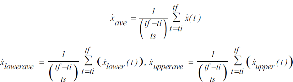
where tf, ti and ts are the final time, starting time and sampling time, respectively.
Note that the controller will be switching in and out to provide robotic assistance. In order to ensure smooth switching, a switching mechanism that we have previously shown to guarantee bumpless switching for satisfactory force response (Mallapragada 2006) is used in this work. This mechanism modifies the position reference, which is the input for the inner loop of the force controller, at the time of the switching in such a way that it is equal to the position reference at the time before switching occurred. The control action in (10) can be modified as below:
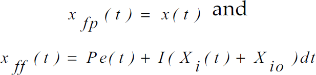
Here x
fp
(t) is the position reference when the controller is not active, which is equal to the position of the human/robot x(t) · x
ff
(t) is the position reference determined using the P and I gains when the controller is active, X
i
(t) represents the integral action and X
io
is the initial condition of the error integrator. e(t) is defined as the F
d
– F
i
. If t
s
is the time of switching, then equation (13) can be used to find the position reference just before the time of switching:

where

The integral action associated with the controller is reset during the switching so that:

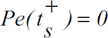
The force error defined as F
d
– F
i
is set to zero just after the time of the switching for a small period of time. Hence:
After the time of the switching F
d
which is calculated using (7), and F
i
, which is recorded from the force sensor are provided to the controller. The initial condition X
io
is defined as:
Then, substituting (15)–(17) into (14) we can observe that

This relation ensures that the position reference is indeed continuous during switching which guarantees bumpless activation and deactivation of the controller.
In this section we present the experiments and the results of the experiments with unimpaired participants.
Experiments
Experiment Procedure
Participants are seated in a height adjusted chair as shown in Fig. 1 (top left). The height of the PUMA 560 robotic manipulator has been adjusted for each participant to start the tracking task in the same arm configuration. The starting arm configuration is selected as shoulder at neutral 0° position and elbow at 90° flexion position. The task requires moving the arm in forward flexion to approximately 60° in conjunction with elbow extension to approximately 0°. Participants are asked to place their forearm on the hand attachment device as shown in Fig. 1 (bottom left) when the starting arm configuration is fixed. The push button has been given to the participants that can be used during the task execution in case of emergency situations (Fig. 1- bottom middle). The participants receive visual feedback of their position on a computer monitor on top of the desired position trajectory (Fig. 1-top right). Participants were asked to execute the tracking task 50 times.
Description of the Experiments
We had conducted two experiments to evaluate the proposed assistive controller. In the first experiment, the participants were required to perform the tracking task without any external resistance applied to his/her upper arm. Participants were asked to track the position trajectory displayed on the computer screen. The participant's
In the second experiment, we asked the participant to perform the same task as in Experiment 1; however, in this case, the participant's arm movement ability was constrained with a resistive band (Thera-bands). This was done to simulate the movement of a stroke patient who may experience variable stiffness during the course of motion. In order to apply resistance to participant's upperarm, a mechanism was designed as shown in Fig. 3. Thera-bands are color-coded into many levels of resistance, thus different color resistive bands can be selected in order to simulate different stiffness of the stroke patient's arm. We selected the green (heavy) color resistive band for our experiment, because it provided sufficient resistance to participant's movement while not inhibiting their ability to complete the task. The mechanism has a rod which can slide right or left to change the position of the attachment and can be used for both right-handed and left-handed participants. The rod has holes on it to adjust the location of the resistive band on the upper arm that may vary among participants. The resistive band is connected to the participant's upper arm through a soft strapped attachment to prevent the participant's arm from the irritation that may be caused when the band is stretched. A seat-belt mechanism that connects the rod to the resistive band attachment can be used to release the rod from the resistive band quickly.

Initially No Resistance is Applied to the Participant's Upper Arm, Fig. 3b. Resistance is Applied to the Participant's Upper Arm in the Direction of Motion as the Task Begins
Three female and one male participants within the age range of 25–30 years took part in the experiments that were described in above. All participants were right-handed. In these experiments (i.e., Experiments 1 and 2 as described in above), the participant tried to track the desired position trajectory by visually looking at the computer screen. Each participant performed the task 50 times for each experiment.
In the first experiment (E1), each participant performed the tracking task without any external resistance applied to his/her upper arm. The idea was to assist the participants as and when they were out of the velocity band. It was noticed that the participants needed less assistance from the robot as they practiced more (Table 1). This result implies that the participants learned how to accomplish the task with practice.
Number of Times Robot Assisted for E1

Number of Times Robot Assisted for E1
Now we present the detailed analysis of the data for one participant (P1) as an example to demonstrate the effectiveness of the assistive controller. This data represented P1's 50th trial. It could be observed from Fig. 4 that the participant's average velocity (dots), which was calculated every 5 seconds using (14), was out of range at A, B and C points. The controller was activated for the next 5 seconds to provide robotic assistance in order to take participant's velocity inside the velocity boundary, thus the controller was active between A-A', B-B' and C-C' (Fig. 5). It could be seen that the participant's velocity was brought inside the desired range at A', B' and C' points (Fig. 4), which verified that the assistive ability of the proposed controller.

Calculated Average Velocities for Experiment 1
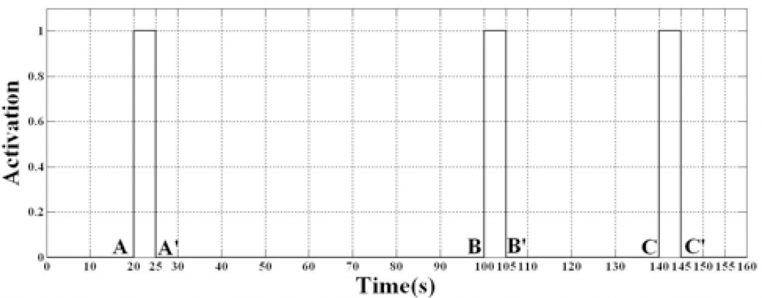
Assistive Controller Triggering
We further analysed the amount of time taken by the assistive controller (t
s
, in seconds) to take
Settling Time for E1

Thus it can be observed from the above set of results that the proposed controller could assist as and when needed and the provided robotic assistance could quickly (i.e., in approximately 0.55 seconds) bring the participant's velocity in the desired range.
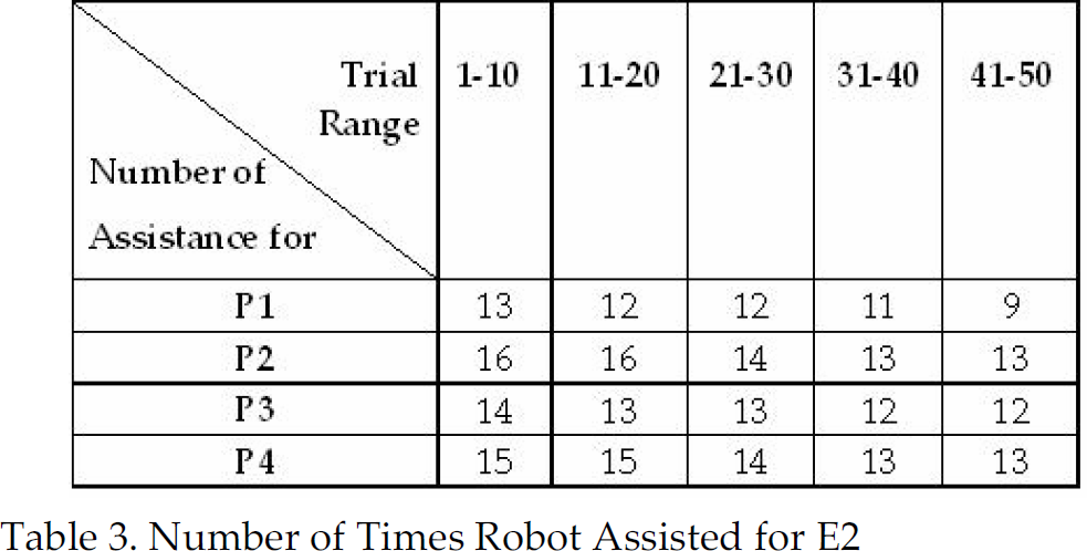
In the second experiment (E2), the participant's arm movement ability was constrained with a resistive band as shown in Fig. 3. The participants were asked to track the desired motion by visually looking at the screen as before. It was observed that the participants needed more robotic assistance when their motion was constrained. It could also be observed from Table 3, participants learned how to accomplish the task with practice. We present the mean and standard deviation of the settling time of the assistive controller in Table 4 for all participants' data when they performed E2.
Number of Times Robot Assisted for E2
Settling Time for E2
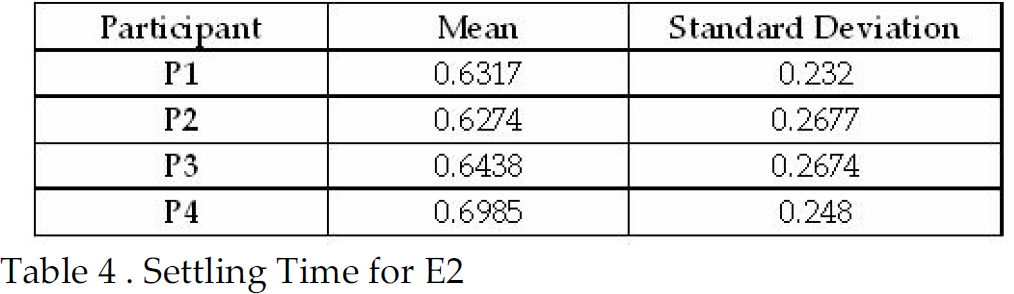
The second experiment was conducted to observe the performance of the controller in an artificially constrained motion scenario, which might provide insight about applying the system to stroke patients whose movement could be naturally constrained. It can be observed that the controller was able to assist as and when needed and could bring the actual velocity of the participant's arm within the desired range in about 0.65 seconds.
We have designed a movement tracking task where the participants not only make repetitive movement but also pay attention to the desired speed of motion from visual feedback. The task was designed in such a manner that it required cognitive processing. Including cognitive processing in the task design is an important criteria because it had been previously shown that the movement tracking task that requires cognitive processing achieved greater gains for brain reorganization of stroke patients than that of movement task that does not require cognitive processing (Carey 2005, 2006).
We have presented a controller to provide robotic assistance to participants to complete the movement tracking task. The assistive controller is evaluated with unimpaired participants. The results have demonstrated that the controller provided robotic assistance to participants as and when needed and quickly brought the participant's velocity in the desired range (i.e., in approximately 0.55 seconds for Experiment 1 and 0.65 seconds for Experiment 2).
We have used a switching mechanism to guarantee bumpless activation and deactivation of the controller.
We have shown that the participants needed less assistance from the robot as they practiced more, which implies that the participant's ability to complete the desired motion within a defined velocity range have been improved. Improving the velocity of patient's movement could be an important criterion to measure the success of a rehabilitation therapy.
We are aware that a PUMA 560 robot might not be ideal for rehabilitation applications. However the use of the hand attachment device, which has been described in Section 2, provided a quick release mechanism to protect the participant's arm from injuries. Note that the presented assistive controller is not specific to the proposed rehabilitation robotic system but can be integrated with any previously proposed rehabilitation robotic system.
An important direction for future development involves testing the usability of the proposed assistive robot controller with stroke patients. Functional magnetic resonance imaging (fMRI) procedure can be used to investigate whether the presented task that included cognitive processing result in long-term brain reorganization.
Footnotes
6. Acknowlegments
We gratefully acknowledge the help of Dr. Thomas E. Groomes who is the Medical Director of Spinal Cord and Traumatic Brain Injury Program, and therapist Sheila Davy of Vanderbilt University's Stallworth Rehabilitation Hospital for their feedback about experimental setup and task design during this work. The work was supported by Vanderbilt University Discovery grant.