
Abstract
This article proposes a novel method that combines real-time image recognition with choosing target object real-time localization in unknown environment. The position information of the object recognized as a target is provided by laser, which avoids collecting all the objects position information in the environment. This can save the computation resource and improve the real time. Furthermore, this article realizes the autonomous back and forth navigation in unknown environment and companies voice prompt and intelligent searching of the target object. This will set up a basis on building a complete environment map. Finally, the experiments show the validness of the proposed method and improve the intelligence of the environment information collection.
Keywords
Introduction
The development of science and intelligent control technology has expanded the research and application of service robot. 1 Service robot is a kind of semi-autonomous or fully autonomous robot. Service robot can complete the service work for human health. Service robot can be divided into professional service robot and personal/family service robot. And the service robot for personal and family use is currently the focus of research. Service robot is automatic machine with perception, planning, and action ability. NAO robot has many abilities similar to humans that other robots cannot achieve. 2 The autonomous navigation of robot in the complex environment is a fundamental research topic for service robots. 3 However, autonomous navigation in the complex environment is important for the robot to complete the task independently. Autonomous navigation of robot also demonstrates the intelligence of robot filed.
Vision is necessary for the autonomous navigation of humanoid robot. 4 Humanoid robot can acquire vision information through camera and it can recognize objects through camera, just like the human’s eyes. 5 People expect that computers can process the information obtained from the environment like the human vision system. 6 Computer vision is used to simulate the human vision function. The computer can extract information from graph or graphic sequence and recognize the shape and motion of objects in the environment. 7 Image feature extraction and matching are important to achieve automatic image registration. The object recognition algorithm mainly has three types:scale-invariant feature transform (SIFT) algorithm, Haar feature algorithm, and generalized Hough transform algorithm. 8 Haar feature recognizes objects by a large number of features using pattern recognition methods to identify the classifier. 9 The rectangular feature is only sensitive to some simple graphic structure, such as edges and line segments. So Haar feature can only recognize structures of specific directions (horizontal, vertical, and diagonal). Although Hough transform algorithm is significant, it has some shortcomings. The detection rate is too slow to accomplish the real-time control. Since Hough transform algorithm is not accurate enough, wrong judgments are made and the desired information cannot be obtained. At the same time, it can produce a large amount of redundant data, and its robustness is poor. SIFT algorithm 10 was proposed by D.G. Lowe in 1999, and it was refined and summarized in 2004. SIFT was presented as key point feature. The feature is invariant to the scaling and rotation of image. And the feature has strong adaptability to illumination and image deformation. In the meantime, this feature also has high discrimination ability in favor of subsequent match. Therefore, SIFT algorithm used to recognize the objects has good practical application in humanoid robot autonomous navigation. However, it imposes a large computational burden, especially for real-time systems such as visual odometry. Speeded up robust feature (SURF) 11 is a robust local feature detector, which can be used in computer vision like object recognition or 3D reconstruction. It is partly inspired by the SIFT descriptor. The standard version of SURF is several times faster than SIFT and is more robust against different image transformations than SIFT. However, the scale and the rotation change less than SIFT, the rotation is not much worse than the SIFT. Ethan et al. 12 proposed Oriented FAST and Rotated BRIEF (ORB) algorithm. ORB algorithm has fast accuracy and can be applied in complex environment real-time accurate detection of moving targets. However, ORB algorithm does not have scale invariance, and the feature point matching effect is poor when the image scale changes. In summary, SIFT algorithm has the best practical performance, but it is also the most time-consuming algorithm in the complex environment. Therefore, in order to improve the real-time performance of SIFT algorithm and further improve the accuracy of the extraction of complex environmental features, Harris corner detection is added to SIFT algorithm, which can judge the target object accurately and efficiently.
The core problem of robot autonomous navigation is the simultaneous localization and mapping (SLAM). In this article, extended Kalman filter (EKF) estimates the state space of the robot pose and landmark positions simultaneously and can demonstrate the correct estimation errors. 13 –15 Linearization error is one of the major factors leading to the EKF-SLAM inconsistency, but most of the SLAM problems are nonlinear. The process of linearization brings greater systematic error caused by the hardware of the robot, so the position error of the robot is increasing gradually in the experiment. There is also a problem which is the external interference. 16 Interference may arise when the robot explores the unknown environment. But for the SLAM, the external interference not only influences the environment mapping but also the robot localization. Thus, the error increases with the error accumulation. In addition, the computational resources needed for the feature-based position estimation by camera are quite expensive. In this article, we use classic EKF-SLAM method as the basic framework, 17 and fractional order controller 18 is used to reduce the deviation in NAO robot walking. We use the laser to provide the position information of the target object to EKF-SLAM. Finally, the laser is used to build the environment map.
The research on SLAM problem usually assumes that the feature of the environment is static (i.e. the landmark location of the environment does not change), but the real environment is often dynamic. Therefore, it has practical significance to study the SLAM problem in the dynamic environment. 19 We study the SLAM problem in the dynamic environment. The landmark locations are different when the robot walks forward and back.
A complex experimental scene is designed based on the ability of human when walking forward and back. The experimental scene is placed with three landmarks. Two landmarks are used when the NAO robot moves forward. And the third landmark is used when the NAO robot walks back, as shown in Figure 1. The landmarks used in the experiment are only regarded as a walking sign guiding the motion of the robot, which can demonstrate accuracy and efficiency more intuitively for the proposed algorithm in the feature extraction and matching. It can prove that the algorithm can realize the recognition of the object accurately in the unknown environment. Therefore, it verifies that the algorithm is feasible and effective in the unknown environment.

The trajectory of the NAO robot walking.
In summary, the main contributions of this work are as follows: An image recognition algorithm based on Harris-SIFT is proposed. Through the feature extraction of the target object, the robot can realize the intelligent recognition of the specific objects in the complex environment and improve the anti-interference ability of the image recognition. Based on laser sensor model, the creation of local environment map is completed, which provides a good reference for the study of robot autonomous walking. Combining the Harris-SIFT identification algorithm, the laser sensor positioning technology with the EKF-SLAM algorithm, the autonomous walking of the robot in the indoor environment is realized by introducing the intelligent voice prompt and the intelligent search of the target object.
The main contents of this article include the following parts. The “Fundamental knowledge” section introduces the fundamental knowledge used in this article, including the introduction of object recognition algorithm and building map using laser. The “Experiment results” section shows the experimental results, and the “Conclusion and future work” section summarizes the article.
Fundamental knowledge
Object recognition algorithm
In this article, computer vision is used to perform the object recognition of humanoid robot. The object recognition is how to extract the feature point of the image. The process of the feature points extracted by the traditional SIFT algorithm is complex and needs a lot of computation, which inevitably generates the information redundancy by comparing the matching results. The traditional SIFT algorithm cannot reflect all the object feature information and can result in more mismatched points easily. In order to reduce the mismatched points, the Harris-SIFT algorithm is used in this article. The high-contrast corner points are chosen as feature points of the image, which can make the feature points reflect the object recognition better. The experiment results of this article show the effect of object recognition. The corner points of the image are the points of the most pixels gray transformation or the maximum of the contour curvature values. The corner point can capture the image information well.
Harris corner detection
The main idea of Harris corner detection algorithm
20
is that if the surrounding pixels display the existence of more than one direction, we believe that the point is the interest point, known as corner. We define the symmetric semidefinite matrix

where
The purpose of the scale-space theory is to simulate the multiscale features of the image data. So the scale space of the two-dimensional image is defined as follows

where G(x, y, σ) is the variable scale Gaussian function, (x, y) is the spatial coordinate that represents the pixel position of the image, the symbol * represents convolution, and σ is the scale-space factor. The smaller the σ value is, the less smooth will be the image and the smaller the corresponding scale. Large scale corresponds to the profile feature of the image, and small scale corresponds to detailed feature of the image.
In order to detect the stable key points in the scale space effectively, the scale-space difference of Gauss (scale-space DOG) is proposed. It is generated by using different scales Gauss differential kernel and image convolution. D(x, y, σ) represents the scale-space difference of Gauss, L(x, y, kσ) represents the scale space of the two-dimensional image, and k represents the different scale

The purpose of the convolution

where
In the case that the feature values need not be actually calculated, the indicator function
Figure 2 shows the experimental scene. Figure 2(a) is a picture taken from the NAO robot. Figure 2(a) shows the real-time acquisition of objects and environmental information by the camera during the navigation of the NAO robot. Figure 2(b) is the pixel value distribution of the picture from Figure 2(a). The response function of the Harris corner detector without concrete symbol is calculated for each pixel. For the response function of each pixel, the scipy.ndimage.filters module (Gaussian derivative filter) in Python is used to calculate the derivative

Experimental scene. (a) The picture of experimental scene taken from the NAO robot, (b) The pixel value distribution of the picture from Figure 2(a).
Based on the above theoretical knowledge, the specific implementation process of the corner extraction is as follows: The corner point response function is achieved by Gaussian derivatives and written in Python. The scale size of the Gaussian filter is defined by the parameter σ. By modifying the parameter σ, the Harris matrix is calculated by trying the different scales of average operations at different scale parameters in x and y directions. When σ value is large, the smooth and denoising of the image are good, but the image information becomes fuzzy. When σ value is small, the smooth effect and denoising of the image are poor, but the image information is clear. So according to experience, in this article σ = 3. An image of the pixel value of the Harris response function value is returned by the corner point response function. In order to produce good corner detection results, all the selected pixel values of the image points are higher than the threshold and the additional restrictions (i.e. the interval between the corners must be greater than the minimum distance between the sets). Figure 3 shows that the smaller the threshold value, the more the extracted corners. But the corresponding computation will increase with the more corner. When the threshold is 0.1, the experimental results are good and the computation can be reduced according to Figure 3. So the threshold in this article is 0.1. All the candidate pixels are sequenced according to descending order of the corner response value. Then, the distance among the points in the region of the corner position is marked, while the points near the region of the corner position are removed from the candidate pixels. According to the Harris corner detector, the detection results are different through changing the threshold value. The detected results are shown in Figure 3.

Harris detection results. (a) The threshold is 0.01, (b) The threshold is 0.05, (c) The threshold is 0.1.
Harris-SIFT match algorithm
Interest point descriptor is a vector assigned to the interest point, and it is the apparent information to describe the image information near the interest point. The better the descriptor is, the better the corresponding point can be found. The corresponding points or correspondence of points are used to describe the pixels of the same object and scene points at different image. In the “Harris corner detection” subsection, interest point position descriptor can provide the position and scale information of the interest point. In order to obtain rotation invariance, SIFT descriptors introduce reference direction based on the image gradient direction and size around each point. The main direction uses the histogram (based on weight) to the measurement. In the study of Chen and Cai, 22 Harris descriptor uses the image brightness information to calculate the normalized cross-correlation matrix. Harris descriptor calculates the gray value of the pixel block of the images. There are more mismatched points for the matching results produced by Harris descriptor. Compared with the SIFT descriptors, the cross-correlation matrix of image pixel block is described weakly. And Harris descriptor does not have the features of the scale invariant and rotation invariant, while pixel block size of Harris-SIFT algorithm will affect the corresponding matching results. So a more robust method 23 (i.e. SIFT descriptor) is used to deal with these corresponding matches. The procedures of Harris-SIFT algorithm are expressed in Algorithm 1.
Harris-SIFT algorithm.

Descriptors are calculated based on the information of position, scale, and direction. In order to obtain stable image brightness, SIFT descriptor uses the image gradient. SIFT descriptor selects subregion grid in the neighborhood of each pixel. In each subregion, SIFT descriptor calculates histogram in the image gradient direction. Histograms of each subregion are merged into descriptor vector. The standard SIFT descriptor is 4 × 4 subregions, and each subregion uses direction histogram of eight short intervals. It will produce a total of 128 histograms of short intervals (4 × 4 × 8 = 128). Figure 4 shows the building process of SIFT descriptors. The point with 4×4 subregions in the left side of Figure 4 is the corner point extracted by Figure 3, and the right shows the eight direction histogram of each subregion.

The creating process of Harris-SIFT descriptors of the picture in Figure 2(a). SIFT: scale-invariant feature transform.
We use Python to write the code to extract the interest point information, including coordinates, scale, direction angle, and the 128-dimensional vector information of the corresponding descriptors. The information is stored in a readable format in text file. The text file is automatically created by the code in the image processing. The information is different according to different images and different feature points.
SIFT feature vector has removed the influence of scale change, rotation, and geometric distortion, then the length of the feature vector is normalized and the influence of the illumination changes can be further removed. After the SIFT feature vector of two images is generated, the Euclidean distance is used as the key point measurement to determine the similarity of two images. We take one key point of matched image and find out the least Euclidean distance of the first two key points compared matching image. By comparing the feature points of matching image and matched image, we can judge if it is a reasonable point. In these two key points, if the least distance divided by the second least distance is less than the ratio threshold, then the matching points are accepted. If the ratio threshold is reduced, the number of SIFT matching points will be decreased, which will be more stable.
The match function uses the angle between vectors of descriptors as the distance metric. The descriptor vector is normalized to unit length. This match is one way, and each feature in one image will be matched with all the features of another image. In order to increase the robustness of the match, the procedure of match process is repeated once again. That is, the features of the second image are matched with the features of the first image. Finally, we only keep the features which meet the match criteria of the two images at the same time. This method can remove incorrect match features and keep good match features. Of course, some correct match features will probably be removed. The match results are shown in Figure 5.

The matching result of the two images.
In our previous research, the image recognition used color-contour algorithm. The comparison between the Harris-SIFT algorithm and color-contour algorithm is shown in Table 1. From Table 1, Harris-SIFT algorithm is better than color-contour algorithm. And the Harris-SIFT algorithm has more applicability. But not all objects (e.g. water pipes and color balls) can use Harris-SIFT algorithm to recognize the images. In this article, Harris-SIFT algorithm is used to recognize the images.
Comparison between color-contour algorithm and Harris-SIFT algorithm.

SIFT: scale-invariant feature transform.
Building map using laser
The laser sensors have many advantages, such as using simplicity, high accuracy, high resolution, and strong anti-interference ability. So we use laser sensor to build the environment map. In this article, the laser sensor of NAO robot is Hokuyo URG-04LX with the scanning period of 0.1 s, and its resolution is 0.36 degrees. URG-04LX laser sensor can scan a maximum of 240 degrees and 4 m, and it will return 684 × 4 data. Because the original data obtained by the laser scanning are not accurate, original data need to be processed. According to the laser scanning data, the line feature is extracted and the surrounding environment can be mapped. In this article, the iterative segmentation method and least squares fitting method are used to finish the laser mapping work.
(1) Iterative segmentation algorithm. Iterative segmentation algorithm is to divide the region of raw data obtained by laser. Then, the data of each region are connected and fitted. The procedures are as follows: a. Calculating the distance Di between two points b. Judge the regional segmentation point

The size of threshold δ is set and the relationship of Di and δ is judged. The value of δ depends on experience. If Di > δ, the ith point is considered as the regional segmentation point. Then, we can get the N divided regions. After the regional division is finished, the number of discrete points in each region is tested. If the number is less than five, it is discarded as noise points.
(2) Least squares fitting. We suppose that a measurement vector P of N range is given and it bears tuples,

Line extraction diagram.
The least squares fitting method is to minimize the sum of the squared errors. It can be described as the following steps.
(a) Calculate the distance di of each Pi from the line

(b) Sum up the square of

(c) Seek the extreme value point
where r, α are the parameters that define the line. The line extraction algorithm is expressed in Algorithm 2 and the map building algorithm is given in Algorithm 3.
Line extraction algorithm.

Map building algorithm.

Because the NAO robot has visual graph software Monitor, the Monitor can show the environment data obtained by the NAO robot laser shown in Figure 7. We deal with the data by iterative segmentation algorithm and least squares fitting in Figure 8. Figure 8(a) shows the result of data processed from laser by iterative segmentation algorithm. If the distance between two points is larger than 20 cm, then we think they are two objects. Figure 8(b) shows the result after using least squares fitting method and it is the environment map. The map is clearer by using least squares fitting method. And the processed information is transmitted to the NAO robot. In the case of environmental information which is more complex, there will be a lot of invalid data points. If the data points are less than five after iterative segmentation algorithm, then we regard them as invalid data points. And after the least squares fitting method, we can remove these data points without affecting the experiment as shown in Figure 8(b).
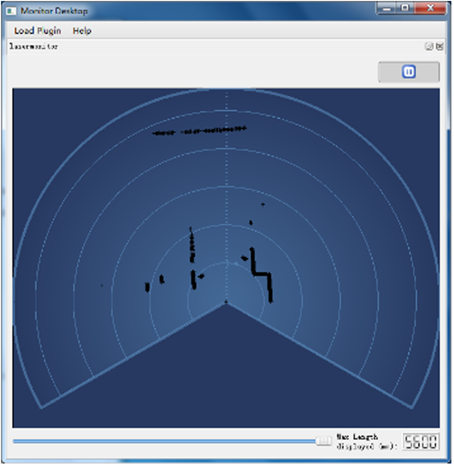
The environment information obtained by laser from Monitor.
Data processing. (a) The result of extracted data by using iterative segmentation algorithm, (b) The processed result of Figure 8(a) by using least square fitting.
Experiment results
In this article, the improvement is based on previous research works of Wen et al. 24,25 Wen et al. 24 realized the SLAM path planning of the NAO robot. But the proposed method in the research work of Wen et al. 24 requires the NAO robot to learn target object first. The recognition is unstable and easy to be influenced by external interference. A fractional order controller is added in the NAO robot walking to reduce the error because of the interference and noise. 25 And the method proposed in the work of Wen et al. 25 does not use camera to recognize the objects. NAO robot will regard all the objects detected by laser as target objects, which results in excessive calculation.
In this article, we require the NAO robot to finish complex and autonomous navigation. The experimental scene is shown in Figure 9. In Figure 9, we set two forward landmarks and one back landmark. And they are not set in line. The NAO robot walks forward for a distance, then turns around and walks back. In order to exhibit the intelligence of the NAO robot, we design a novel navigation process. The whole navigation process will company with the NAO robot’s speaking which responses to the NAO robot’s action. The detailed procedure is explained later.

Experiment scene.
In order to test the search ability of the NAO robot, it is placed in the direction without facing to the target position of the object in Figure 9. At the beginning of the experiment, the NAO robot will look for the recognized landmarks. Figure 10 shows two kinds of landmarks which need to be recognized by the NAO robot when it walks. Figure 10(a) and (b) are the recognized landmark when the NAO robot walks forward and back, respectively. The landmark recognition uses Harris-SIFT algorithm whose procedures are expressed in Algorithm 1. Experiments show that the Harris-SIFT algorithm can recognize the images well.

The landmarks of walking forward and back. (a) The landmark of walking forward, (b) The landmark of walking back.
If there exist recognized landmarks, the NAO robot will walk forward. If not, the NAO robot will turn right. The NAO robot will continue to look for landmarks until it finds one. If none is found, NAO robot will turn 360 degrees and tell us “no object found, experiment ends, thanks.” We set 40 degrees as the rotation angle when the NAO robot turns right (the rotation angle can be changed depending on the experiment environment). The NAO robot will walk forward when it recognizes the target object. In order to show the intelligence of the NAO robot, the NAO robot will speak when it performs every action. The detailed process is introduced later. When the target object is recognized by the NAO robot, the environment map is built according to Algorithm 3 and sent to the NAO robot.
The NAO robot walks to the target object. This article designs a safe distance of 30 cm between the target object and the NAO robot. If the distance is 30 cm, then the NAO robot turns right to look for the next target object. There are three landmarks in this experiment. Two landmarks are used in the walking forward process, but only one landmark will be seen by the NAO robot every time. The rest of the landmarks are used in the walking back process. When the number of landmarks recognized by the NAO robot is more than 2, the forward task will finish. Then, the NAO robot will walk back and undergo the similar recognition process, just like walking forward. The experiment of walking back will finish when the NAO robot finds the distance between the target object and the NAO robot is 30 cm. The navigation process algorithm is demonstrated in Algorithm 4.
Navigation algorithm.

Experimental system algorithm is shown as Algorithm 4. T1 is the amount of all landmarks. T2 is the amount of forward landmarks. N is the threshold of match scores, and N is 5 in the article. m is the threshold of the safe distance, and m is 30 cm in the article. The flow of the navigation process is shown in Figure 11. In Figure 11, distance1 represents the distance between robot and first forward landmark, distance2 represents the distance between robot and second forward mark, and safe_dis represents the safe distance between robot and landmarks. In the article, the safe distance is set as 30 cm.

The experimental flow.
The detailed experiment procedure is as follows: At the beginning, the NAO robot will say: “Hello, I am NAO, experiment begins, my following task is to find target object.” The NAO robot begins to look for the target object. If the NAO robot finds nothing, then NAO robot says: “No object, turn right, keep searching.” Then, the NAO robot continues to look for the target object. When the NAO robot finds the target object, it will build the environment map and say: “Building map.” When the map building finishes, the NAO robot says: “Object found, moving forward.” Next the NAO robot walks forward to the target object. During the process of the NAO robot walking forward, NAO robot will detect if the target object is in the view of the NAO robot. If there is no target object, the NAO robot will turn right and look for the next target object. When the distance between the target object and the NAO robot is 30 cm, the NAO robot will say: “Too close, turn right, keep searching.” When the number of the target object is more than 2 in the walking forward process, the walking forward task is over. And the NAO robot will say: “Forward ends, go back.” Then, the NAO robot walks back. When the distance between the target object and the NAO robot is 30 cm, the walking back process finishes. And the NAO robot will say: “Experiment ends, thanks.”
Figure 12 shows the landmark recognition results by using Harris-SIFT algorithm. Figure 12(a) shows the recognition results of the first landmark after the NAO robot turns right at the first time. Figure 12(b) shows the recognition result of the second landmark. Figure 12(c) shows the recognition results when the NAO robot walks back. During the experiment, as the NAO robot gets closer to the target object, the number of matching points increases gradually and then gradually decreases. Figure 13 shows the whole experiment process. Figure 14 shows the trajectory of the NAO robot autonomous navigation. The dotted line with pentagram is the trajectory. A pentagram represents one step of the NAO robot. The scope constituted by a black “+” represents the landmark position of laser sensor observation. The pentagrams in the middle of the circle represent the actual position of landmarks. The dots around the landmarks represent the estimated position of landmark observed by the NAO robot. Hollow ellipses represent the covariance matrix.
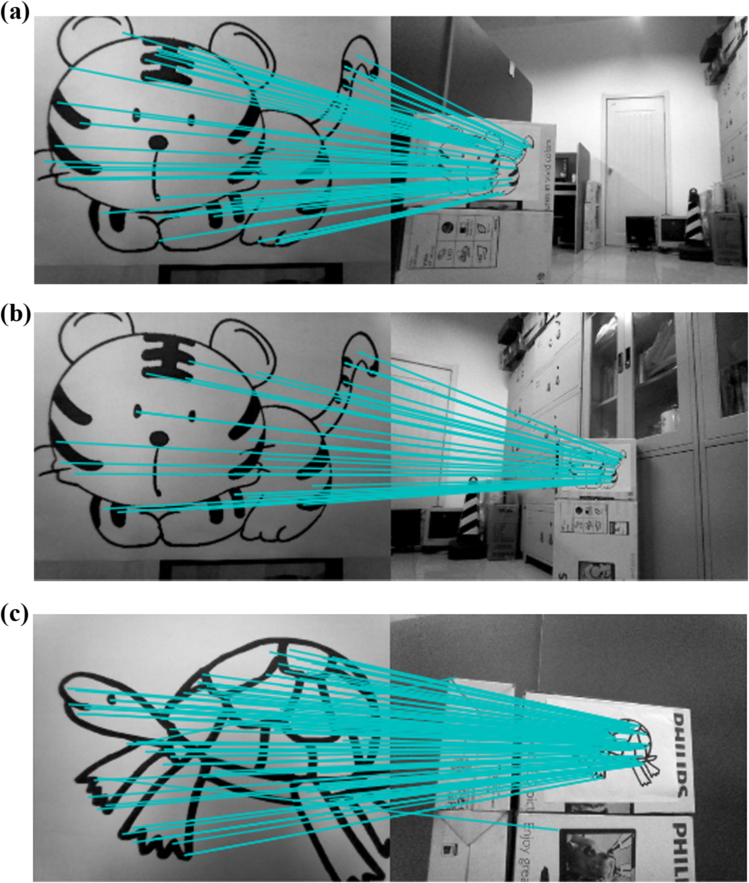
The recognition result of all landmarks by Harris-SIFT algorithm during walking forward and back. (a) The recognition result of first landmark during walking forward, (b) The recognition result of second landmark during walking forward, (c) The recognition result of the landmark during walking back. SIFT: scale-invariant feature transform.

The experiment processing.

NAO robot walking graph.
Comparing with our previous work, the research contributes to the research field by fulfilling a more complex task. In the studies by Wen et al., 24,25 the robot can only walk forward and use laser to detect the object, which has limit. The robot cannot see the object just like blind man only if laser is used. Laser cannot detect all the objects, such as glass. The experimental results show that the proposed algorithm in this article is practical and stable. The algorithm proposed in this article can be successfully applied in the NAO robot. NAO robot can effectively recognize the target object under the case of illumination variations and the presence of other interferences. We can get the position information of landmarks accurately and build the environment map of the NAO robot by using the laser sensors. The proposed algorithms in this article achieve the task of autonomous walking forward and returning back based on the camera and laser.
Conclusion and future work
In this article, the Harris-SIFT algorithm is used to recognize the landmarks and successfully applied to autonomous navigation of the NAO robot. Experiment results show that the Harris-SIFT algorithm is robust and can recognize accurately. The iterative segmentation method and least squares algorithm are used to build the environment map. And the processed mapping information is transmitted to the NAO robot. The search ability of the NAO robot is also tested which is placed in the direction without facing to the target position of the object. The NAO robot will speak when it performed every action, which shows the intelligence. Experimental validation of the proposed method shows that it is valid to perform autonomous navigation for the NAO robot indoor environment.
Future works will use more experiments in different scenarios and landmarks to prove the robustness of the image detection. We will make robot navigate more autonomously and quickly.
Footnotes
Declaration of conflicting interests
The author(s) declared no potential conflicts of interest with respect to the research, authorship, and/or publication of this article.
Funding
The author(s) disclosed receipt of the following financial support for the research, authorship, and/or publication of this article: The work was partly supported by the National Natural Science Foundation of China (project no. 61773333, 61473248), the Scholars Studying Abroad Science and Technology Activities of Hebei Province of China (project no. C201400355), and the major project of science and technology in Hebei Provincial Education Department (project no. ZD2016150).