
Abstract
Focusing on the problems of material waste, low production efficiency, poor design flexibility and high cost existing in the traditional flange design by conventional casting and machining processes, a flange design method based on wire arc additive manufacturing (WAAM) was first proposed. A parametric finite element model of the pipe connection flange was established, and the stress and deformation of the flange were simulated and analyzed, using ANSYS. It reveals the weak areas in terms of strength and stiffness of the connecting flange. Then, a sensitivity analysis was conducted on the design parameters of the flange structure. High-sensitivity structural parameters were selected as the optimization design variables. With the minimum volume and weight as the objective functions and the strength and stiffness as the constraint conditions, a robust optimization design model for the pipe connection flange was established. The optimal structural design parameters were obtained by using the orthogonal array test method. The automatic modeling, stress simulation analysis, and lightweight design of the flange structure have been achieved. The new design method proposed in this paper can significantly reduce the design time, material consumption and production cost of flanges, while improving the reliability and safety of pipe connection flanges.
Keywords
Introduction
Flanges are essential mechanical components used to connect pipelines, equipment, and fittings, and they are widely applied in industries such as petroleum, natural gas, chemicals, power generation, and aerospace. These components often operate under complex conditions, including high temperature, high pressure, and dynamic loads, making the design and manufacturing quality critical to the safety and reliability of pipeline systems. 1 However, traditional flange manufacturing processes rely on conventional machining technologies such as milling, turning, and drilling. While these methods excel in the mass production of standardized components, they face challenges such as inefficiency, material waste, and lack of flexibility in small-batch or customized production. 2 This is particularly evident in customized production and the need for rapid responses to market demands, where the limitations of traditional flange manufacturing processes become more pronounced. 3 With the rapid development of additive manufacturing (AM) technologies, particularly the emergence of wire arc additive manufacturing (WAAM), new opportunities have arisen to transform traditional flange design and production processes. Additive manufacturing, by building components layer by layer, significantly reduces material waste compared to machining, simplifies the production process, and enhances design flexibility.4,5 As a highly efficient additive manufacturing method, WAAM has been widely adopted in aerospace, automotive, and other fields, gradually becoming the ideal choice for manufacturing large metal components due to its high deposition efficiency and lower material waste. 6 Particularly in the production of heavy metal components, WAAM enables the efficient fabrication of complex geometries through precise control of the arc heat source and metal flow.7,8 Despite significant progress in various fields, applying WAAM in flange design and manufacturing is still at the beginning stage.9,10
In recent years, increasing research has focused on integrating additive manufacturing with pipeline and equipment components, demonstrating that AM can significantly optimize the mechanical properties of parts while shortening production cycles and reducing costs.11–13 In the lightweight design of mechanical components, AM improves component design efficiency and material utilization through topology optimization and automated modeling techniques.14–16 Through numerical simulations and real-time monitoring systems, residual stresses generated during the AM process can be effectively controlled, improving the precision of the final product.17,18 The application of WAAM in component design, especially optimizing components for the petroleum and chemical industries, has advanced material selection and enhanced the durability and safety of components under extreme operating conditions.19,20 However, a comprehensive comparative analysis of AM technologies remains relatively scarce in existing literature, particularly compared with other AM techniques such as laser metal deposition (LMD) and electron beam melting (EBM). Compared to laser-based additive manufacturing, WAAM offers higher deposition efficiency in large-scale production and demonstrates distinct advantages in manufacturing heavy metal components. The arc heat source of WAAM provides significant benefits for manufacturing large, complex metal parts, a feature particularly advantageous in producing pipeline connection flanges.
Multiple studies that explore parametric design and optimization techniques for additive manufacturing have supported the growing interest in AM’s potential for enhancing structural design. Integrating functionally graded materials in AM improves mechanical properties, particularly in components like pipeline flanges. A strong focus has also been placed on parametric optimization and topology optimization methods that can tailor components to achieve lightweight designs and high structural efficiency, key goals for flange development in industries with demanding operational conditions. 21
Research on advanced parametric design techniques has shown the importance of automating the design process to reduce time and costs, and parametric modeling approaches have demonstrated their potential to revolutionize traditional design processes. 22 Furthermore, the integration of machine learning and digital twin technologies has been investigated to enhance design and manufacturing processes, thereby improving both efficiency and accuracy in the production of complex components like flanges.23–26
Although additive manufacturing has made significant progress in several areas, its application in flange design and manufacturing is still in its early stages. Existing research primarily focuses on the mechanical properties and material selection in the additive manufacturing process. However, studies on integrating WAAM technology with flange design and manufacturing processes have not been reported. The gap filled by WAAM lies in how to economically and efficiently produce ‘larger, heavier’ key metal components while achieving integrated structural and performance design. This is precisely the manufacturing challenge for large-caliber, high-pressure flanges. Traditional forging and machining methods face difficulties such as the challenging acquisition of giant forgings, long production cycles, and extremely low material utilization rates (<20%). Existing powder-based direct energy deposition technologies, due to the dual limitations of ‘build size’ and ‘deposition cost’, are unable to penetrate this field. Therefore, the rationale for this study is that the high deposition rate, unlimited build space, and low-cost characteristics of WAAM are highly compatible with the manufacturing needs of large flanges, making it the only additive manufacturing technology that can compete with traditional manufacturing at this scale. Specifically, how to leverage the advantages of additive manufacturing to enhance flange structural performance, reduce production costs, and meet customized production demands through innovative design approaches, remains an unresolved question. Consequently, there is an urgent need to conduct research in this area.
This study aims to develop a comprehensive parametric design model encompassing both standard and non-standard flanges, employing finite element analysis to investigate the stress and deformation characteristics of pipe connection flanges. It seeks to identify weak areas in flange structural strength and stiffness, perform sensitivity analysis of structural parameters, determine optimization design variables, construct an optimization model, and propose optimization strategies to enhance flange performance, reduce manufacturing costs, and minimize flange weight. Furthermore, by integrating additive manufacturing technology with flange design, this research not only introduces a novel approach for efficient and cost-effective flange design but also provides valuable guidance for the application of additive manufacturing in traditional manufacturing sectors. Through this innovative integration, the study is poised to drive a transformation in flange design and manufacturing processes, improve production efficiency, meet customized production demands, and address the inherent limitations of conventional flange manufacturing techniques.
High-capacity class flange design
Design and analysis of the flange based on WAAM technology
Wire arc additive manufacturing (WAAM) technology, integrated with flange design, represents an emerging research direction that offers considerable advantages over traditional cast flanges. Firstly, WAAM technology achieves high material utilization, reducing waste, and lowering costs. In contrast to conventional casting, which requires the creation of molds and generates substantial amounts of gating, risers, and waste, resulting in lower material efficiency. This method enables a material utilization rate exceeding 90%, with minimal waste, significantly cutting material costs. Secondly, WAAM offers greater design flexibility, allowing for the production of complex structures. Traditional manufacturing methods are constrained by mold fabrication and casting limitations, making it difficult to realize intricate internal geometries (such as cavities, complex channels, etc.). On the other hand, WAAM directly manufactures components from 3D models, enabling the creation of complex geometries and internal structures with ease. This facilitates the fulfillment of design requirements such as lightweight and functional integration. Thirdly, WAAM flanges exhibit superior mechanical properties. During the casting process, defects such as poverty and shrinkage can compromise the mechanical performance of the final product. By contrast, wire arc additive manufacturing flanges benefit from precise process parameter control, resulting in a dense microstructure that enhances mechanical properties (e.g. strength and toughness), often surpassing cast flanges and even approaching or exceeding the performance levels of forged components. 19 Fourthly, WAAM technology is more suitable for lightweight flange designs. It can incorporate lightweight features, such as internal cavities or lattice structures, through topology optimization and other design techniques. This reduces weight but also maintains or even improves strength, aligning with modern design trends toward lightweight and efficient structures. Traditional cast flanges are typically solid and relatively heavy. Fifthly, WAAM-based flanges are particularly well-suited for high-performance materials. Many high-performance alloys, such as titanium and nickel-based alloys, present significant challenges in traditional casting due to their high cost and manufacturing difficulty. However, electric arc additive manufacturing facilitates using a wide range of high-performance materials, making it ideal for applications in extreme environments (e.g. high temperature, high pressure, or corrosive conditions).
Integrating wire arc additive manufacturing technology into the flange design process requires optimizing and adjusting traditional workflows to exploit the advantages offered by WAAM. The design employs topology optimization or lightweight strategies to achieve high-performance and lightweight flanges. The material distribution is carefully selected, and dimensional adjustments are made to balance cost reduction with strength retention. WAAM technology enables the creation of complex geometries that are difficult to achieve using conventional methods. By employing advanced modeling software such as SolidWorks, intricate geometric designs can be directly translated into manufacturable components, enhancing the functional performance of the flange to meet specific operational requirements. Additionally, selecting appropriate materials for the WAAM process is critical. The material choice should be based on the flange’s intended operating environment, such as high temperature, high pressure, cyclic loading, or exposure to corrosive media. Suitable materials might include stainless steel, titanium alloy, or nickel-based alloys, ensuring the flange’s reliability and performance. Lastly, determining the optimal WAAM process parameters and generating efficient deposition paths are essential for achieving the desired results. The layer-by-layer deposition technique facilitates near-net shaping, minimizing the need for subsequent machining and reducing production costs. Figure 1 presents the flowchart of integration WAAM technology into the flange design process.

Flange design flowchart based on WAAM technology.
This study is not to pursue absolute ‘no post-processing’, but to minimize the material removal, processing time, and complexity of machining to the greatest extent, while ensuring functional performance. This is achieved through the following design strategy: reserving more allowance in areas where significant deformation is expected and less allowance in areas with minimal deformation, rather than simply applying a uniform large allowance throughout. This approach minimizes the total cutting volume while ensuring a high machining success rate.
Parametric design of the flange
In the NPS 26–60 range, the size of high-capacity class flanges above Class 900 is not specified in the ASME standard. Based on the diameter of the connected pipe, the size of Class 1500 flanges is specified in the ASME standard. 27 The dimensions of each part of the flange are shown in Figure 2 below.
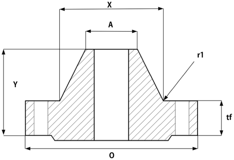
Structural parameters of the flange.
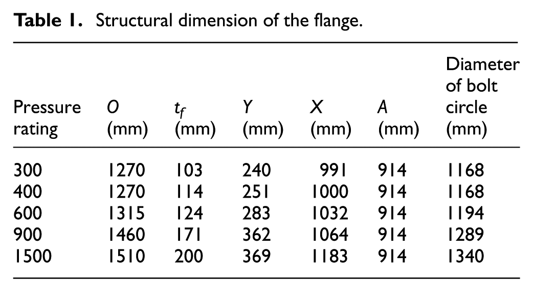
The parameter data for different parts of the NPS 36 flange at various pressure levels are organized and compared, with a focus on a more detailed comparison with the calculated size of Class 1500. The data are presented in Table 1.
Structural dimension of the flange.
By using DriveWorksXpress in SolidWorks, parametric modeling of flanges can be achieved. DriveWorksXpress facilitates the automation of design processes. The core application of DriveWorksXpress lies in achieving rapid automated modeling and drawing generation in SolidWorks through equations, design tables, and configuration-driven rules. This method requires the establishment of a specific set of rules to construct the model.
First, an initial and typical thick-walled flange model is designed. This model is suitable for petrochemical pipelines, featuring a large diameter and numerous threaded holes. During the initial design phase, the flange dimensions are precisely planned, followed by the development of 2D design drawings. Next, within the SolidWorks software, the sketching process begins. Based on the prepared 2D design drawings, the cross-sectional shape of the flange is sketched. The revolve extrusion function is then used to construct the main body of the flange. Finally, using the Hole Wizard feature, holes for fixing bolts are created on the flange plate. These holes are distributed evenly into 20 positions using the circular pattern function. The basic structural modeling of the flange is thus completed, as shown in Figure 3.

3D model of flange.
The DriveWorksXpress tool is used to perform parametric configuration of the flange model. After launching the DriveWorksXpress application, a database is created to store data in the Access database format. During the construction of the Access database, it is essential to identify and extract the valid dimensional data of the flange for storage. Using SolidWorks’ annotation feature, the dimensional information for various parts of the flange can be clearly displayed. This includes the inner and outer diameters of the flange, its thickness, the diameter and quantity of the holes, the flange height, the shoulder and neck heights, as well as the diameter and thickness of the small end. These dimensions and characteristics of the flange are then obtained. When processing the flange model, all factors that influence the model’s dimensions must be identified and selected. These selected dimensions are subsequently stored in the Access database, as shown in Figure 4.

Access saved data.
After completing the entry of all variables that influence the flange dimensions into the database, the next step is to establish a set of editing rules for these dimensional data. These rules are primarily divided into two categories, independently defined dimensional control parameters, where user inputs directly influence the size of specific dimensions, and Interdependent dimensions, where certain dimensions are linked by a specific mechanism. Modifying one dimension will automatically adjust the related dimensions accordingly. The interactions between flange dimensions are primarily governed by strength and stiffness requirements. The internal diameter of the flange must match the diameter of the oil pipeline, while the small end width of the conical neck should be equal to the thickness of the connecting pipeline. Therefore, it is essential to clearly define both the internal diameter of the flange and the small-end diameter of the conical neck during the design process. The large end of the conical neck typically has a thickness three times that of the small end. Additionally, the designed flange model must meet the strength and stiffness requirements during operation.


Here,
With the DriveWorksXpress tool, complete parametric modeling of the flange can be achieved. By running DriveWorksXpress in SolidWorks and entering key dimensional data—such as the flange’s internal diameter, external diameter, and plate thickness—into the interface, the software automatically generates a 3D model of the flange based on the specified parameters, as shown in Figure 5.

Parametric model of the flange.
To visually observe the specific structure of the designed flange, SolidWorks software was used to establish a three-dimensional solid model of the flange, as shown in Figure 6.

Three-dimensional solid model of the flange.
Because the flange is manufactured using electric arc additive manufacturing technology, it offers greater flexibility and convenience in selecting various sizes. Compared to traditional manufacturing processes, the electric arc additive manufacturing flange allows for more extensive optimization across different dimensions, such as the flange’s diameter, rounded corners, and bottom seals.
Calculation of bolt preload
Due to the high hydrostatic pressure within the flange tube, liquid leakage can occur if the flange connection is not securely tightened. Therefore, sufficient pre-tightening force must be applied to the flange bolts to ensure a tight seal at the flange joint. The design must account for the preload and operating states of the flange.28,29
In the preload state, the load applied by the bolt can be expressed as:

Where y represents the unit compression load at the gasket or flange contact surface (N).
In the working state, the load applied by the bolt can be expressed as:

Where: Wm1 is the minimum bolt load required for operation (N); H is the total hydrostatic pressure (N); H p is the total compression load of the joint contact surface (N); G is the diameter of the gasket at the loading reaction force (mm); b is the effective sealing width of gasket (mm); m is the gasket coefficient; p is the design pressure of the pipeline.
The establishment of finite element model of the flange
The three-dimensional assembly solid model of the neck butt welding flange of class 1500 was established according to the dimensions determined above. Since the overall flange structure belongs to the axis metrical structure and the overall flange structure is too large, 1/12 of the overall flange was taken for strength analysis to simplify calculation on the premise of ensuring calculation accuracy. The length of the pipe connected by the flange is determined according to the Saint-Venant principle,
In the assembly, models of the stud, nut, gasket, and washer were imported. The stud was concentrically aligned with the bolt hole of the flange, the nut was concentrically matched with the stud, and the washer was placed between the upper and lower flanges. The final overall assembly model of the flange is shown in Figure 7.
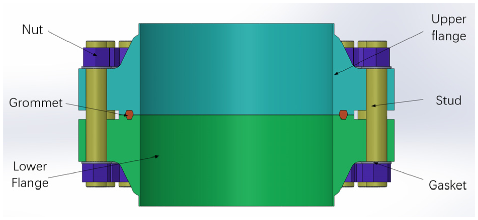
Overall assembly drawing of the flange.
Pre-processing of finite element simulation
To ensure calculation accuracy while improving computational efficiency, the flange assembly model is simplified. This approach reduces the complexity of the model, enabling faster and more concise calculations without sacrificing precision. Additionally, localized mesh refinement is employed in key regions of the model, enhancing the accuracy of the results in those areas while maintaining overall efficiency. This combination of model simplification and mesh refinement reduces the computational workload and ensures the reliability of the analysis.
By taking WAAM-induced effects into account, anisotropy in different directions, residual stresses, and internal microstructural defects of the material can be incorporated into the model based on experimental measurements. These WAAM-specific factors have a certain influence on the prediction of the final strength and stiffness calculations, and the extent of this influence depends on the printing accuracy. If the process parameters of wire arc additive manufacturing are strictly controlled to improve print quality, their impact becomes negligible.
The material settings for the flange assembly include the upper and lower flanges, studs, nuts, and gaskets. The key parameters such as density, specific heat capacity, thermal conductivity, elastic modulus, and Poisson’s ratio—are specified for each component. For strength considerations, the upper and lower flanges are made of A694F70, the studs and nuts are made of 35CrMo, and the gasket material is 304 stainless steel.30,31 Detailed material properties are provided in Table 2.
Material parameters.

Contact modeling in flange assembly simulation
To make the simulation results more realistic, in the overall assembly of the flange, the impact of different contact surfaces on the overall simulation results should be considered. In ANSYS, there are five types of contact modes, namely Bonded constraint, non-separated constraint, rough constraint, frictionless constraint, and frictional constraint. The above contact modes can simulate various practical situations, where the binding constraint indicates that the two bodies have neither normal separation nor tangential separation. The non-separation constraint means that tangential relative movement is allowed between two entities, but normal separation is still not allowed. Rough constraint allows the normal direction to move relative to each other, while the tangential direction does not. Frictionless constraint indicates that there is no friction between two entities, which allows both normal and tangential movement. The friction constraint represents that there is a coefficient of friction between two entities, but it also allows normal and tangential movement. Considering the actual contact of each part of the flange assembly, combined with the existing simulation contact, set the contact as shown in Table 3.
Flange assembly contact.

Analysis of simulation results
For the relatively regular geometry of the flange assembly, the method of multi-area division was selected, the element type was a hexahedral, the mesh size was 15 mm, and the final division element was 183,088 and the node was 39,526. According to the actual situation, in the pre-tightening state, apply the bolt pre-tightening force to the bolt position, apply the restraint to the two ends of the flange for frictionless support, and apply the fixed support to the two sides of the flange. When the actual condition is applied, the uniform load is applied to the inner wall of the flange, and the compression load or tensile load is applied to the flange at both ends of the flange pipe.
According to the pre-tightening force calculated above, it is applied to the flange assembly model to evaluate the strength of the flange. It is necessary to determine the dangerous cross section and point of the flange and calculate the stress intensity and deformation stiffness of the flange at different positions according to the drawn flange path. If the stress is less than the allowable stress, the strength of the flange is considered sufficient. If its deformation is less than the allowable deformation, the flange stiffness is considered adequate, and the flange grid diagram and calculation path are shown in Figure 8.

Finite element model of the flange: (a) grid division and (b) calculation path.
In the preloading state, the equivalent stress distribution under the applied preloading force is shown in Figure 9, with the maximum equivalent stress reaching 349.82 MPa. The equivalent stress distribution of the flange under actual working conditions is also shown in Figure 9, where the maximum equivalent stress increases to 351.93 MPa.

Stress nephogram of flange under pre-tightening state and working state: (a) preload condition and (b) working condition.
Three calculation paths were considered in this study, including both the preload state and working state. The stress calculation results along these paths for the flange are summarized in Table 4.
Path stress of the flange under pre-tightening and working state.
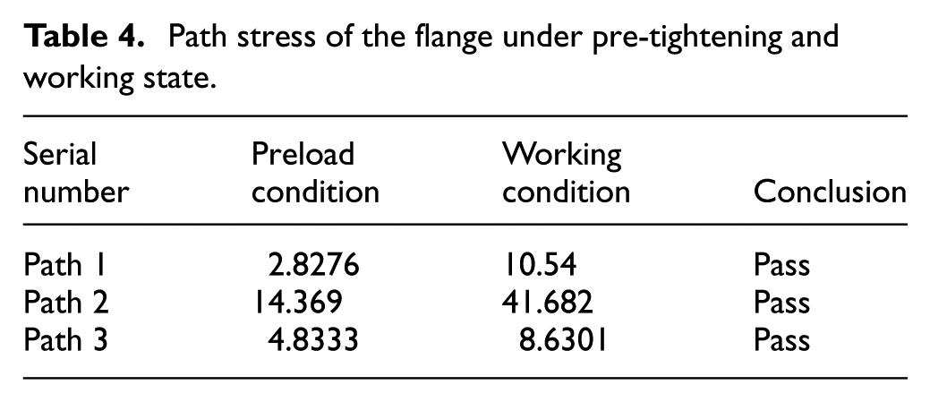
The calculation results in Table 4 show that, under normal conditions, the flange meets the allowable stress requirements of the material when subjected to the preload force.
Robust and optimized design of flange
Sensitivity analysis of structure parameters
To reduce stress, volume, mass, and ultimately the cost of the flange, optimization of the flange dimensions was performed. Key parameters, including flange thickness, fillet radius, and contact chamfer at the pipe port, were initially selected for size optimization. The stress concentration points and weight reduction considerations were taken into account during this process. The analysis of stress distribution and weak areas of the flange is shown in Figure 10.

The cross-section of the flange.
In the flange structure, the following parameters are defined: tf is the flange thickness, D is the end pressure acting on the inner section of the flange, T is the difference between the static pressure of the total end and the static pressure of the applied flange in the internal section of the flange, G is the gasket compression force, G = F − H; H is the total static pressure at the end, d is the radial distance from the bolt circle to the static pressure at the end of the inner section, t is the radial distance from the bolt circle to T, and g is the radial distance from the bolt circle to G.
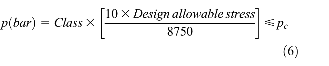
The maximum working pressure of a flange is determined based on the pressure temperature rating of the flange made of different materials. The pressure temperature rating of a flange refers to the maximum allowable working pressure it can withstand at different working temperatures and is an important parameter for selecting standard flanges. The allowable stress for material setting in ASME B16.5 is 8750 psi. For non-standard flanges, specific data provided by ASME cannot be directly referenced, and relevant mathematical formulas need to be used for calculation. The specific calculation formula is as follows.
The maximum allowable stress for flange design is as follows:
Sixty percent of yield strength at room temperature or set temperature (carbon steel and alloy steel) or 70% (austenitic stainless steel).
Tensile strength of 25% at room temperature or set temperature, 1.25.
Allowable stress value determined by long-term high temperature.
The allowable stress calculation for materials is as follows.

σ b is the strength limit of the material, n is the safety factor, usually taken as 1.5–2.5.
The design dimensions of the flange end wall thickness are determined based on the standard pipeline design pressure formula. The design flange outer diameter D is 914 mm, and when t < D/6, the formula related to the design pressure and wall thickness is as follows.
T is the wall thickness of the pipeline, p is the design pressure of the pipeline, S is the allowable stress of the material, E is the quality factor given by ASME related standards, W is the strength reduction factor of the weld joint, and Y is the table factor given by ASME standards.
The basis for optimizing flange thickness is given by an empirical formula.

K is usually taken as a coefficient of 1.1–1.3, P is the design pressure of the pipeline, and D is the outer diameter of the pipeline.
In design, the given design pressure should be greater than or equal to the working pressure to ensure the normal use of the parts. Therefore, when the value of the design pressure in the formula is taken as the working pressure, the minimum wall thickness and minimum thickness of the flange can be calculated to minimize the volume and weight of the flange while still maintaining a strength higher than the standard.
By inputting the known dimensions and coefficients into the pressure temperature rated value calculation formula, the maximum working pressure of the flange can be calculated to be 30.17 MPa. Taking the design pressure as 30.17 MPa and inputting it into the flange end wall thickness and flange thickness calculation formula, the flange end wall thickness is 30 mm and the flange thickness is 175 mm.
This study conducted a sensitivity analysis of the flange structural design parameters and determined the relative sensitivity of each parameter. For structural design parameters with low sensitivity, their influence on the output results is small within a reasonable range of variation. Therefore, they do not need to be considered as optimization design variables, which can greatly reduce the computational workload, improve computational efficiency, and have little impact on the final results. The rationale for choosing these high-sensitivity parameters as design variables stems from robust design theory, the parameters exhibiting high sensitivity significantly affect the system output even with reasonable parameter variations, and thus cannot be neglected. Incorporating them as optimization variables can greatly enhance the accuracy of the results. Minor disturbances in these selected optimization variables produce relatively significant impacts on the flange’s critical strength and stiffness.
Among the structural parameters, the flange thickness and fillet radius have the greatest impact on overall stress and mass. A sensitivity analysis was conducted on these two parameters, with consideration for other dimensional factors. To ensure the flange meets strength requirements, the optimization range for flange thickness was set within 10% of the original size. Flange thickness values were selected equidistantly between 165 and 180 mm, while the fillet radius was varied between 35 and 50 mm.
Stress analyses were performed for the preload, pressure, and working states. Regular curves of flange thickness and strain, as well as fillet radius and strain, were generated and are shown in Figure 11.

The variation law of stress with different parameters: (a) flange thickness and (b) fillet radius.
From Figure 11, the stress at 165 mm is the smallest. However, due to the limitation of actual working pressure, the actual design pressure is lower than the working pressure when the flange thickness is 165. Therefore, the optimal value of flange thickness should be selected as 175 mm, where the stress on the flange is the smallest.
Similarly, in the stress versus fillet radius diagram, the minimum stress is observed when the fillet radius is 45 mm. However, compared to the impact of flange thickness, the fillet radius has a relatively small effect on the overall mass and volume of the flange.
The establishment of flange optimization model
The goal of the optimization design for the target flange is to ensure that the designed product or component meets the imposed constraints and design objectives. Optimization involves adjusting variable parameters to achieve the best combination of factors that allows the flange to meet its design goals. This not only helps reduce material consumption during manufacturing but also lowers transportation costs and simplifies structural installation. The fundamental principle of optimization design is to employ mathematical tools and models to represent the actual engineering problem. An optimization model is then established using a specific method to iteratively solve the problem and ultimately determine the optimal design solution.
Due to the use of electric arc additive manufacturing for producing the flange, there is greater flexibility in the connection to pipes compared to traditional flanges. According to ASME standards, ensuring that it is well aligned with the inner wall of the tube. electric Arc additive manufacturing allows for the precise printing of the flange end with a chamfer, ensuring it is flush with the inner wall of the pipe. This process also minimizes any impact on the neck thickness of the flange, maintaining the integrity of the design while achieving a high-quality connection.
The overall structure of the flange can be divided into several components. By summing the volumes of each individual part, the total volume of the flange can be calculated.

The optimization mathematical model for the flange includes the design variables, objective function, and constraint conditions, as outlined below:


In the optimization model, the following parameters are defined: t f represents the thickness of the flange; r1 indicates radius of the flange transition corner; α indicates the chamfer angle at the connection between the flange and the pipe; β is the angle at the radius of the rounded corner, t is the flange wall thickness, σ i is the actual stress, and (σ) is the allowable stress.
Orthogonal array test of flanges
In optimization models subject to minimum volume/weight and strength/stiffness constraints, the orthogonal experimental method (OEM) leverages its systematic and balanced design-space coverage to thoroughly explore the parameter space at significantly reduced computational expense. By integrating statistical modeling with iterative refinement, it reliably approximates the global optimum. In contrast to the stochastic convergence uncertainty of genetic algorithms (GA) and the application-specific restrictions of topology optimization (TO), OEM delivers a more robust, computationally efficient, and practically oriented approach—especially advantageous for multivariable, multi-constraint engineering problems encountered in practice.
Considering the requirements of the machining center feed system and the constraints of the optimization design model, design variables are defined as a set of adjustable parameters within specific ranges. To select the optimal combination of design parameters, a detailed comparative analysis of numerous design schemes is typically required. To effectively reduce the workload of this analysis process, the orthogonal array test method is introduced to optimize the flange’s volume, mass, and stress design. Three key design variables were chosen as the main factors for the orthogonal experiment. By defining reasonable variation ranges for each variable, a four-level, three-factor orthogonal array experimental table was constructed. The experimental design is presented in Tables 5 and 6.
Factors and levels of orthogonal array test.

Orthogonal array table of four levels and three factors a .

The maximum withstand pressure stress for pipeline design is 30.17 MPa.
According to the standard calculation formula, the flange wall thickness has a positive relationship with the design pressure. The larger the wall thickness, the greater the flange pressure and mass. Therefore, the law of wall thickness and flange pressure is known. If wall thickness is added in the orthogonal experiment, the effect of other parameters on stress will not be obvious, and the optimal parameter combination cannot be correctly found. Therefore, in the orthogonal experiment, the wall thickness value is chosen to be constant, and other parameters are changed to find the minimum stress combination under the influence of other parameters. The optimized value of wall thickness has been determined by the formula of wall thickness design pressure of the pipeline to minimize mass and withstand pressure greater than the original standard flange.
From Table 6, after comparative analysis, the stress is minimized when the thickness is 175 mm, the transition fillet radius is 45 mm, and the pipe connection chamfer is 30°, compared to when the thickness is 165 mm, the transition fillet radius is 35 mm, and the pipe connection chamfer is 60°. Considering the quality and pressure bearing considerations during actual production and flange design, the thickness of 175 mm, the transition fillet radius is 45 mm, and the pipe connection chamfer is 30° are ultimately selected as the optimized design parameters. The calculation results of the flange end wall thickness are selected with the same design pressure as the working pressure. The above parameter selections can ensure that the flange has the lightest weight while the maximum pressure bearing is greater than the original standard flange. The stress comparison cloud map of the flange assembly before and after optimization is shown in Figure 12.

Stress comparison of flange assembly before and after optimization: (a) before optimization and (b) after optimization.
The strain nephogram of the electric arc additive manufacturing flange, before and after optimization, are shown in Figures 13 and 14. Figure 13 illustrates the strain distribution of flange before optimization, while Figure 14 shows the strain distribution of flange after optimization.

Strain nephogram of flange cross-section before optimization.

Strain nephogram of flange cross-section after optimization.
To observe the stress and strain distribution across the entire flange, a full simulation of the flange was conducted. The reliability of the model was verified based on these simulations. The overall simulation analysis results of the flange are presented in Figure 15.

Overall equivalent stress-strain nephogram of the flange: (a) overall strain nephogram and (b) overall stress nephogram.
The maximum stress after optimization is significantly lower than that before optimization, indicating that the reliability of the optimized model is higher than before optimization. The maximum strain of the flange is located at the contact part with the pipeline. After optimizing the corresponding chamfer angle, the strain at the end of the flange is significantly reduced, indicating that the optimization of the flange model effectively reduces the generation of strain. The maximum pressure temperature rating of Class1500 standard flanges before optimization is 25.86 MPa, while the optimized pressure temperature rating of flanges manufactured using wire arc additive manufacturing is 30.17 MPa, an increase of 16%. The quality has also decreased from 1856 kg for standard flanges to 1721 kg, a decrease of 7%. The costs can be saved by 30%–90%.
The WAAM equipment required for manufacturing very large-diameter flanges has been independently developed, and the 3D printing of the optimized flange parameters obtained in this paper has been completed. The validation of the model was further achieved through physical prototype testing, which included pressure, leakage, and strength experiments. The simulation results demonstrated strong consistency with the experimental data, thereby substantiating the validity and accuracy of the finite element model.
Conclusion
This paper focuses on oil pipeline connection flanges as the research subject, applying wire arc additive manufacturing (WAAM) technology to the field of flange design and production. It investigates parametric modeling and lightweight design methods for flanges, the main conclusions of this study are as follows:
A parametric modeling approach suitable for both standard and non-standard flanges is proposed, and a flange parametric model based on WAAM is established, achieving fully automated three-dimensional modeling of flanges. This approach opens a new pathway for flange design and manufacturing while laying the foundation for subsequent high-efficiency design optimization.
Finite element analysis is used to simulate the strength and stiffness of flanges, examining the stress and deformation characteristics of pipe connection flanges under real-world operating conditions. The analysis identifies weak points in flange structural strength and stiffness, which are used as constraints for optimization design. Sensitivity analysis of key structural parameters is conducted, determining flange thickness, corner radius, flange wall thickness, and inner chamfer as design variables for structural optimization.
An optimization model for flange structure is developed with the objective of minimizing volume and weight. Using a partial orthogonal array experimental test method, optimal structural design parameters for flanges based on WAAM are obtained. Compared with the traditional flange design method, the maximum pressure-bearing capacity is improved by 16%, and the weight is reduced by 135 kg. This achieves performance optimization and lightweight design of flanges, addressing the current challenges in flange design and manufacturing, such as low efficiency, high costs, and material waste.
Although some fruitful research results have been achieved in wire arc additive manufacturing at present, in-depth and systematic research is still needed in aspects such as the design criteria of WAAM parts, optimization of processing and manufacturing process parameters, anisotropic behavior and mechanical property experiments, so as to be rapidly promoted and applied in more fields.
Footnotes
Handling Editor: Aarthy Esakkiappan
Funding
The authors received no financial support for the research, authorship, and/or publication of this article.
Declaration of conflicting interests
The authors declared no potential conflicts of interest with respect to the research, authorship, and/or publication of this article.
Data availability statement
Data will be made available on request.