
Abstract
To address conventional high-pressure cleaners’ inherent issues of excessive size, high noise levels, and poor small-space suitability, this study employs TRIZ theory for systematic analysis and solution development. The core innovation involves replacing traditional pumps with a novel linear motor, leading to a compact and low-noise design. Electromagnetic and fluid dynamics simulations, validated by experiments, confirm that the optimized prototype achieves a maximum thrust of 150 N, an outlet diameter of 4 mm, and an operating water temperature of 40°C for optimal performance. Compared with traditional pump products, the developed cleaning machine exhibits empirically verified significant advantages in noise reduction, jet velocity, and structural compactness, providing substantial strategic support for industrial transition toward high efficiency, environmental sustainability, and intelligent development.
Introduction
The cleaning machine is a specialized cleaning device capable of removing contaminants such as dirt, dust, and impurities from object surfaces, primarily employed in industrial production, healthcare, and daily cleaning services, serving as an essential tool to ensure smooth production processes and deliver high-quality cleaning services. Among various types of cleaning equipment, jet cleaning machines are the most widely used in industrial equipment, pipelines, and vehicle cleaning. Current research on jet cleaning machines mainly focuses on optimizing cleaning efficiency and water conservation. Li et al. 1 investigated cleaning agents for greenhouses in mainland China and found that existing equipment primarily employs high-pressure spray systems (operating pressure up to 0.8–1.2 MPa), adaptive crawler chassis, and machine vision-based contamination recognition modules to enhance cleaning efficiency. Dalal et al. 2 achieved a 35% reduction in consumable costs while significantly improving cleaning performance by combining an eight-nozzle high-pressure jet system (operating pressure of 2.08 bar) with 80% fluid recovery technology. Jeon et al. 3 integrated large-capacity high-pressure water tank systems with translational scrapers to enhance cleaning efficiency in livestock farming. These studies demonstrate that generating high-pressure water flow through water pump pressurization is a common method to improve cleaning efficiency in current jet cleaning machines. However, excessive pressure not only generates sharp high-frequency noise, typically reaching 90 dB, but also results in bulky pump sizes that hinder operation in confined spaces. Therefore, advancing research on optimizing the working principles of jet cleaning machines to enhance cleaning performance, reduce noise pollution, and achieve compact designs represents a crucial direction for improving environmental adaptability and user convenience of these machines.
In recent years, linear motors have demonstrated extensive application potential across multiple industrial sectors, owing to their high efficiency and direct coupling capability with driven components. 4 Particularly in the field of fluid machinery, they offer a new feasible approach for reliability-oriented design of pump equipment. Xiang et al. 5 based on a mechanical-hydraulic-load coupling model, revealed that under sinusoidal input signals and multi-pump parallel configurations, linear motor reciprocating pumps not only exhibit significantly enhanced output performance but also achieve a substantial reduction in flow pulsation rate. Furthermore, the application of linear motors has expanded to scenarios such as electric hammers, transport systems, and long-stroke high-precision positioning. For instance, Wróblewski et al. 6 realized efficient operation of electric hammers, while Yu et al. 7 effectively overcame the limitations of traditional rotary motors by leveraging their high power density and adaptive control capabilities. These advancements fully attest to the technical potential of linear motors in achieving low-noise and high-efficiency operation.
The Theory of Inventive Problem Solving (TRIZ), developed by Soviet inventor Genrich Altshuller and his team through analyzing millions of patents, constitutes a systematic methodology for resolving various design conflicts and provides significant guidance for product innovation.8–10 This theory has demonstrated remarkable achievements in industrial equipment miniaturization. Şimşit et al. 11 successfully implemented compact innovative designs for rotor field winding services by directly applying the TRIZ framework, proving its effectiveness in fundamental structural optimization. Peeters et al. 12 developed novel lightweight pressure-sensitive snaps based on TRIZ’s technology evolution roadmap, offering forward-looking lightweight solutions for electronic products. For deeper analytical insights, Kamps et al. 13 systematically deconstructed and redesigned bionic components for additive manufacturing by combining functional modeling with knowledge effect databases, achieving biomimetic light-weighting at complex system levels. Kocoń and Skarka 14 directly applied TRIZ methodology to focus on rim structures, developing breakthrough designs that contributed efficient design pathways for lightweight structures.
Building upon TRIZ’s demonstrated effectiveness in industrial equipment lightweight design,15,16 the unique contribution of this study in introducing TRIZ theory lies in the systematic application of methods such as the system function model, function trimming, and substance-field analysis to the overall configuration reconstruction of jet-cleaning machines. This breaks the path-dependence on high-pressure water pumps and, at the fundamental level of energy transfer and conversion, seeks the simultaneous resolution of multiple conflicts—energy consumption, noise, and volume. This research addresses the issues of high energy consumption, excessive noise, bulky size, and poor adaptability to small spaces in jet cleaning machines. By employing TRIZ’s system function model, the study identifies insufficient and harmful functions in cleaning machines, then designs a compact linear motor-driven electric cleaner based on function trimming, substance-field analysis, and conflict resolution theory. Numerical simulations establish a mathematical model correlating linear motor thrust with fluid outlet velocity, supported by electromagnetic field simulations using ANSYS Maxwell and fluid dynamics analysis via Fluent software. Prototype development follows, with validation through motor thrust testing and actual cleaning performance evaluation. Results show strong agreement between simulation and experimental data, confirming model validity and providing reliable scientific foundations and practical engineering references for optimizing compact cleaner designs.
Structural design and optimization
Structural analysis and design of cleaning machines
Market investigations have shown that the most commercially available jet cleaning machines primarily rely on high-pressure water pumps as their central component. These high-pressure cleaning systems generally consist of a high-pressure pump, electric motor, inlet and outlet valves, input and output chambers, and flow conduits. The electric motor controls the motion direction and water pressure of the high-pressure pump. The input fluid is pressurized to a higher pressure, and the high-pressure water is subsequently transported through the input chamber to the nozzle, thereby enabling the cleaning function.
By employing the TRIZ methodology and focusing on functional aspects of system components, the cleaning machine was defined as a technical system with the primary function of removing surface contaminants from objects. The system components were identified as the high-pressure pump, electric motor, inlet valve, outlet valve, input chamber, output chamber, flux tube, nozzle, and main body. The super-system components were identified as including the water tank, water (as the fluid medium), cleaning objects, and operator, as shown in Table 1.
Component analysis of the cleaning machine.

Based on system component decomposition principles, interrelationships between the cleaning machine’s subsystems and super-system components were analyzed to construct its functional model. 8 As shown in Figure 1, the functional model revealed that the primary function of the cleaning machine was to clean object surfaces through water supply from the high-pressure pump. However, harmful functions, such as noise and vibration generated by the operation of the high-pressure pump that interfered with the motor operation, were also identified. TRIZ component trimming methodology, substance-field parametric analysis, and conflict resolution theory were systematically applied to eliminate these detrimental interactions. In Figure 1, the components that were functionally interacted with in the cleaning machine during the jet operation were indicated in red, while the static or fixed components of the system were represented in green.
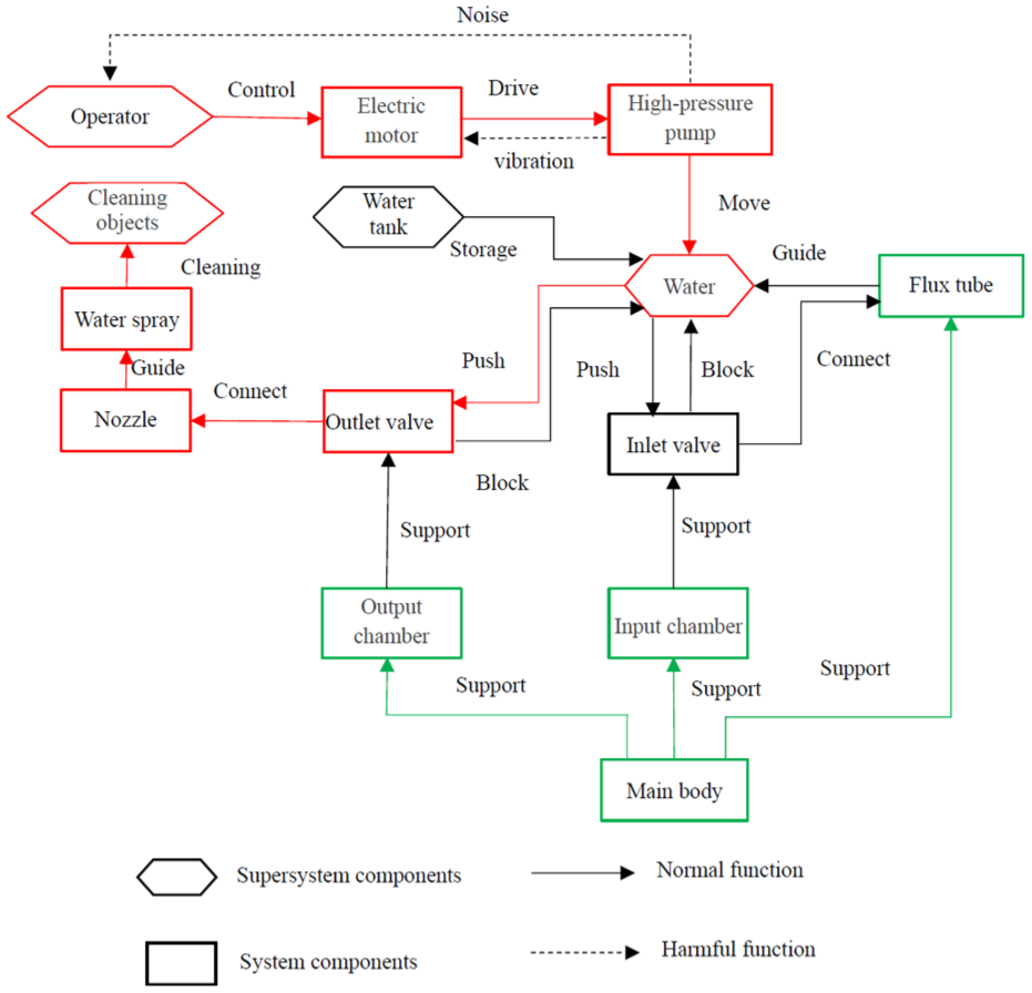
Functional model of cleaning machine.
Application of TRIZ methodology for structural optimization of cleaning machines
Functional component trimming
Component trimming is a method within the TRIZ methodology. It is employed to eliminate deficient, harmful, or redundant functions within the functional model. This process thereby enhances the overall functional efficiency of the system. The functional model in Figure 1 revealed that the operation of the high-pressure pump generated high-decibel noise. This noise is harmful to both operators and the surrounding environment. It also leads to high energy consumption, classifying it as a harmful function within the system. Additionally, the direct drive of the pump body by the electric motor caused vibrations that disrupted the stable operation of the motor, representing another harmful function. Based on these findings, the negative-effect model of the cleaning machine was established, as shown in Figure 2. Since the operator is a component of the super-system and cannot be removed, the electric motor and high-pressure pump were trimmed. The functional model of the cleaning machine after trimming is shown in Figure 3.

Negative effect model of cleaning machine.
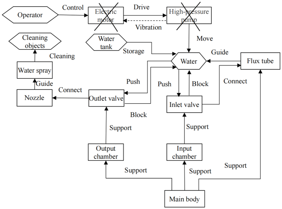
Trimming function model of cleaning machine.
Substance-field model analysis
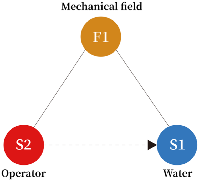
The Substance-Field (Su-Field) analysis method is a key technique within the TRIZ theory. It is primarily used to construct problem models for technical systems. These models are then refined using the standardized solution tools provided by the TRIZ framework. 17 As shown in Figure 3, water flows into the input chamber. It then passes through the conduit and reaches the output chamber. However, the operator could not directly manipulate the water. This inability is due to the lack of mechanical interaction between the operator and the water. As a result, an ineffective and incomplete Su-Field model is formed, as depicted in Figure 4.

Ineffective and incomplete model.
In accordance with the standard solution tool, specifically the principle S5.2.3, 18 an additional substance is introduced into the system, such as a gravitational field or the thrust of water. This action generates an interactive field within the water, enabling the displacement of water. However, this approach fails to control the magnitude of the water flow. As a result, the effectiveness of the Substance-Field model is insufficient, as illustrated in Figure 5. Within the TRIZ Substance-Field analysis method, the issue associated with this model is addressed using the S2.1.1 chain Substance-Field model. This solution involves incorporating two new elements into the original model: an additional substance, S3 (“piston assembly”), and another field, F2 (“mechanical field”). The introduction of these two new elements significantly enhances the control over the water flow, as shown in Figure 6.
Model with insufficient field.
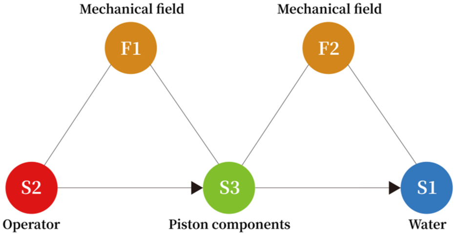
Effective functional model.
Conflict resolution theory
Conflict resolution theory has been extensively adopted as a methodological framework in product design and manufacturing processes to systematically address contradictions. Specifically, parameters of a technical system are represented by 39 universal engineering parameters. Conflicts arising between these parameters can be effectively resolved by applying 40 inventive principles. 19
To achieve the objectives of low noise, high cleaning efficiency and adaptability for multiple usage scenarios in the cleaning machine, the “piston assembly” shown in Figure 6 was identified as the target for improvement. The transformation of the piston assembly into an automated version requires the introduction of an additional power control component. However, this modification inevitably increases the overall complexity of the cleaning machine structure. This leads to a technical contradiction, where the improved parameter is automation and the worsened parameter is complexity. The selection of these specific parameters from the 39 engineering parameters was based on the following process: the improvement objective (automation of the piston assembly) was mapped to the parameter “Automation,” while the resulting negative effect (increased structural complexity due to the added component) was mapped to the parameter “Complexity.” By consulting the technical contradiction matrix, three inventive principles were identified as potential solutions, as shown in Table 2.
Specific solutions derived from inventive principles.

Theory of technological evolution trend
According to the TRIZ theory of technological evolution, the law of dynamic evolution is one of the typical evolutionary laws of a system. Its technical trajectory is characterized by the system evolving along a flexibility pathway, described as: rigid body → articulated mechanisms → compliant structures → hydrostatic assembly → pneumatic configurations → field-controlled mechanisms. 20 As empirically validated in Table 2, Solutions 1–4 demonstrated adherence to this evolutionary trajectory. Specifically, the evolution progressed from movable and stationary ring components (Solution 1), to telescopic structures (Solution 2), to automated movable bodies (Solutions 3 and 4). Based on the evolutionary trend, the field state was identified as the ultimate direction of current technological evolution. By investigating advanced technical solutions for “controlling object movement” in the field of transportation systems, it was found that linear drive systems are becoming increasingly prevalent. This type of linear motor structure can be regarded as a rotary motor that has been sectioned along the radial direction and then straightened. Its stator (primary part) and mover (secondary part) are both composed of rectangular structures. This technical solution was subsequently transferred to the cleaning machine to control the linear movement of water. Given that the cleaning machine is a sealed hollow structure, the TRIZ law of harmony of sub-systems was applied to rationally configure the linear motor. The evolutionary trajectory of the coordination among the sub-systems of the linear motor within the cleaning machine progressed from simple shapes to compound shapes, then to integrated shapes, and finally to dynamically controllable shapes, as shown in Figure 7.

Evolutionary trend of linear motor in the cleaning machine: (a) unilateral structure, (b) bilateral structure, (c) integrated structure, (d) dynamic controllable structure.
As shown in Figure 7, the cleaning machine is mainly composed of main body, piston rod, permanent magnet, coil, magnetic yoke, and sealing ring. The initial scheme is shown in Figure 7(a). The linear motor assembly is designed outside the cleaning machine, the permanent magnet is fixed on the piston rod, the coil is fixed on the yoke and the coil in the permanent magnet generates ampere force to push the piston rod to move in a straight line after being energized. However, this scheme was bulky and the presence of magnetic leakage at the end compromised the thrust efficiency.
To solve the problem of insufficient thrust, Multi coil layout was duplicated from the original single-sided coil, as shown in Figure 7(b). This modification enhanced the magnetic field strength and increased the thrust density. However, compared to the design in Figure 7(a), the structure became more complex.
According to the evolutionary trajectory toward an “integrated shape,” the magnetic yoke was merged with the main machine body, and the formerly straight coil was reconfigured into a toroidal winding that conforms perfectly to the body contour (Figure 7(c)). This design iteration achieved a more streamlined structure and higher thrust density. However, it still faced challenges related to large overall dimensions and inadequate heat dissipation.
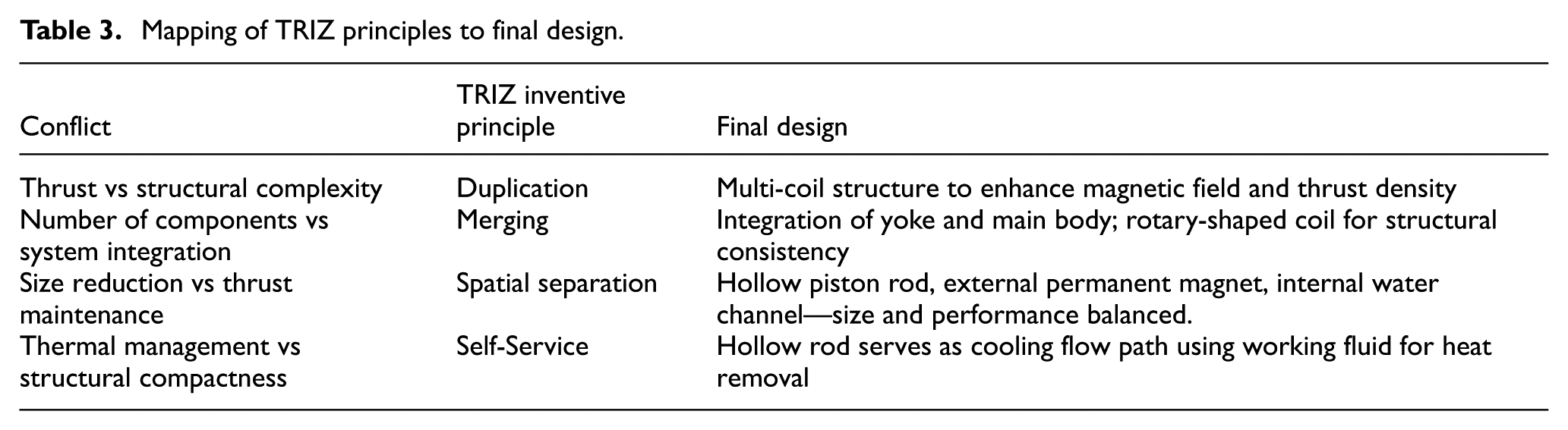
Reducing the length of the permanent magnet and the piston rod in the existing design effectively simplified the overall dimensions but decreased the thrust of the permanent magnet. This created a physical contradiction between size reduction and thrust maintenance. To resolve this contradiction, spatial separation was applied. The piston rod was configured as a hollow shaft, its interior converted into a water-flow channel while the permanent magnet was rigidly mounted on the external surface, as shown in Figure 7(d). This configuration fully utilized the internal space of the main body, effectively resolving the physical contradiction. Additionally, the hollow water flow channel removed a portion of the generated heat, thereby enhancing the overall efficiency and operational stability of the system. The mapping between TRIZ inventive principles and the final design decisions was given in the Table 3.
Mapping of TRIZ principles to final design.
Structural optimization of cleaning machines
Based on the mapping Table 3, the overall structure of the new cleaning machine was further designed, as shown in Figure 8. The input chamber and output chamber were located on the left and right sides of the main body. Check valves were installed within the chambers to control the direction of water flow. The flow channel was rigidly connected to the mover. The power section utilized a linear motor for driving. The stator of the linear motor consisted of an excitation coil and an iron core, while the mover was constructed with permanently magnetized bodies arranged in an alternating orientation. The multi-coil parallel structure reduced magnetic losses and enhanced the output force of the linear motor.
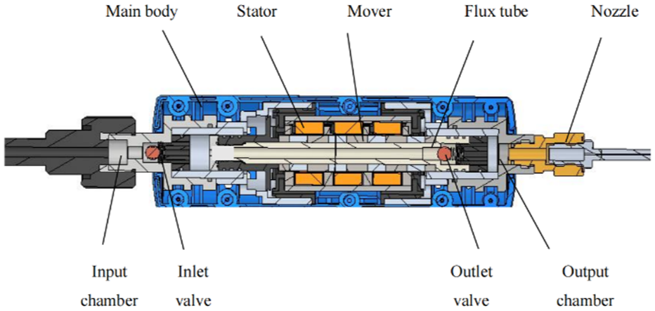
Structural design scheme of the new cleaning machine.
During operation, when current was applied to the stator, the electromagnetic force between the stator and the mover caused the flow channel to move to the right. This created a negative pressure in the input chamber. Under atmospheric pressure, the inlet valve opened, allowing water to enter the flow channel. When the current in the stator was reversed, the flow channel moved to the left. The inlet valve then closed due to the spring force, while the outlet valve opened under water pressure. Water flowed through the outlet valve into the nozzle and was sprayed out at high pressure to complete the cleaning process.
Numerical simulation of linear motor thrust
Development of thrust model for linear motor
To simplify the modeling of the electromagnetic force on the mover of the linear motor, the following assumptions were made: the magnetic permeability of the stator core was considered to be infinitely large, its magnetic reluctance being much smaller than that of the air gap so that neglecting the core reluctance would not substantially affect the model’s accuracy; the difference in magnetic permeability between the mover poles and air was neglected, iron losses were ignored as a reasonable engineering simplification, and the magnetic flux of the mover poles was assumed to be linearly related to position. The magnetic flux provided by the permanent magnet is denoted as

Similarly, the magnetic flux expression at the right end of the stator can be derived. The distribution pattern of this magnetic flux is consistent with that at the left end, with the only difference being a phase shift related to the length of the mover
Based on electromagnetic field theory, the variation in the position of the permanent magnets induces a periodic change in the magnetic flux density within the stator core. This variation subsequently influences the energy storage between the magnetic poles and the stator. The formula for calculating the energy stored in the air gap is presented as follows.
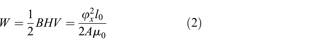
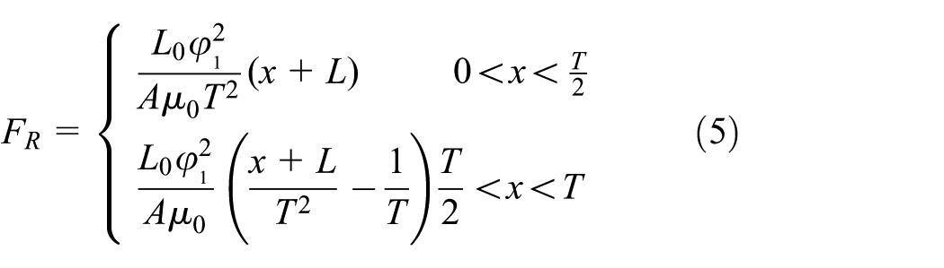
The thrust equation on the left side:
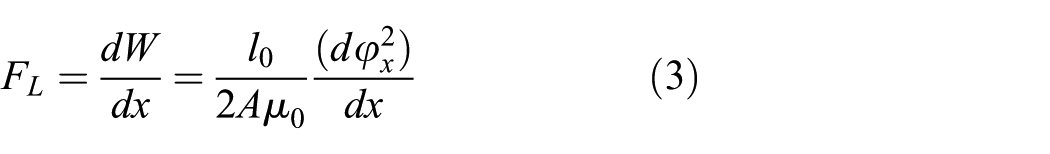
Further derivation of equation (3):

The thrust equation on the right side:
Where,
Simulation results and analysis of motor electromagnetic force
The finite element simulation model of the linear motor was established in ANSYS Maxwell according to the design scheme and mathematical model. The permanent magnet is set as NdFe35, the stator winding is specified as copper, the stator and mover materials are designated as steel and the magnetic conductive ring material between permanent magnets is defined as DT4. The motion region and external boundaries were set as vacuum. Considering the central symmetry of the motor, only a half-model was adopted to simplify the calculations. After setting appropriate mesh parameters, excitation current, coil turns, and motion range, the magnetic field analysis was conducted to determine the maximum thrust of the motor in the model.
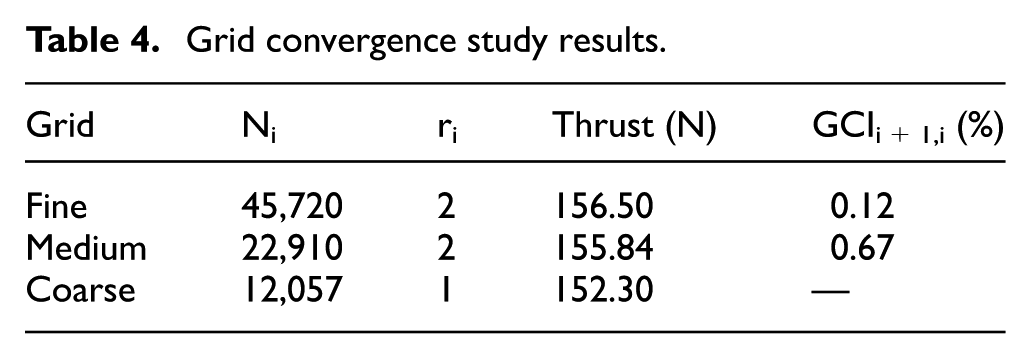
To ensure that the automatically generated initial mesh (22,910 elements) met the computational requirements, a mesh independence verification was performed. 21 The original mesh was refined and coarsened to obtain three different mesh scales—coarse, medium, and fine—and simulations were compared under these three configurations (Table 4). The results showed that the differences in thrust calculation under different mesh scales were negligible, with corresponding Grid Convergence Index (GCI) values of 0.12% and 0.67%, both at a low level. This confirms that the number of mesh elements has a negligible impact on the predicted motor thrust, indicating that the original mesh settings are reasonable.
Grid convergence study results.
Numerical simulation of the motor magnetic field was performed using ANSYS Maxwell. Initially, the magnetic field distribution and flux density contours were computed, with the magnetic flux density variation analyzed. Then, under different excitation currents, the winding magnetic flux curves were extracted, and the thrust characteristics at different starting positions were simulated. Finally, the relationship between coil current and thrust was established.
The magnetic flux lines distribution of the motor were shown in Figure 9(a). The openings on the upper and lower sides exhibit some leakage flux. In contrast, the magnetic field lines in the middle region penetrate the coil vertically, achieving a flux of 0.01 Wb, indicating effective magnetic energy utilization. The magnetic field strength distribution was depicted in Figure 9(b). The figure showed the details of the magnetic field distribution. It indicated fluctuations in the magnetic field strength at both ends of the motor. A local flux density of 21.72 T was also shown, which aligned with the results presented in Figure 9(a).

Simulation results of linear motor: (a) magnetic field distribution and (b) magnetic flux density distribution.
By adjusting the excitation current of the linear motor, the variation in the magnetic flux linkage of the winding over time could be simulated, as shown in Figure 10. The results indicate a linear relationship between the magnetic flux linkage and the excitation current. Specifically, higher excitation currents correspond to increased magnetic flux linkages. When the excitation current is set at 2 A, the maximum magnetic flux linkage reaches 120 Wb, while the minimum value is maintained at 40 Wb. Within the time interval of 0–7.5 ms, the magnetic flux linkage increases with time and then gradually stabilizes.

Magnetic flux simulation curve of linear motor.
With other conditions held constant, varying the initial position of the mover relative to the stator results in the thrust variation pattern shown in Figure 11. When a = 0, the front ends of the mover and stator are aligned. The thrust reaches its maximum value. The variation trend is the most pronounced. When a > 0, the coil structure is forward-shifted. As the value of a increases, the thrust curve of the linear motor shifts to the left.

Thrust curves with different starting points.
Extensive simulations of the linear motor under various excitation currents were performed to obtain the relationship between coil current and electromagnetic thrust, as shown in Figure 12. The results indicated that the electromagnetic thrust increases with the coil current. When the coil current reaches 2 A, the thrust exceeds 150 N.
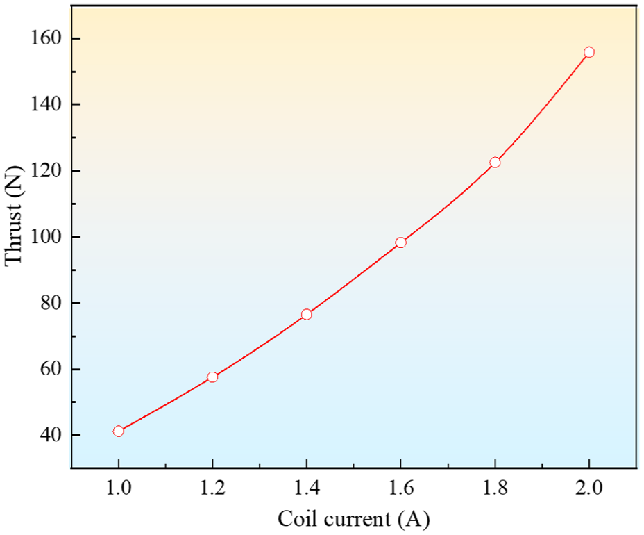
Relationship diagram between coil current and thrust.
Fluid numerical simulation of the cleaning machine
Development of a fluid injection model
Before establishing the fluid injection model of the cleaning machine, it is assumed that the liquid in the inlet and outlet chambers is steady and incompressible and the model is initialized based on the fully filled state, as shown in Figure 13.

Fluid injection model.
According to the principle of energy conservation in fluid mechanics, the sum of kinetic energy, potential energy, and pressure energy at any cross-section within a tube remains constant. Based on this principle, the total Bernoulli equation for the fluid in the cleaning machine can be derived.

Where,
Given that the parameters of the input and output chambers remain constant,

Where,
The pressure at Interface 2 can be determined from equation (7):

Similarly, the pressure at Interface 4 can be derived:
Considering that the outlet is open to the air, the inlet and outlet should satisfy the following equation.
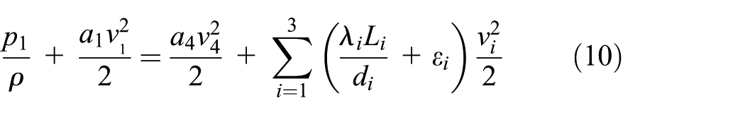

According to equation (11), given the inlet pressure p1, inlet and outlet cross-sectional areas A1 and A4, and other constants, the outlet velocity v4 can be solved using the equation. Additionally, based on the fluid momentum equation, another equation can be established.

By integrating equation (12) and introducing the momentum correction factor β, the pressure F x exerted by the outlet pipe on the fluid can be obtained.

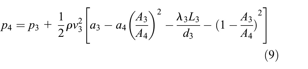
In summary, by applying the fluid energy equation and the momentum equation, a detailed analysis of the pressure transfer and flow velocity of the fluid was conducted. The pressure distribution at each cross-section and the pressure exerted by the outlet pipe on the fluid were obtained. The results indicate that when the outlet cross-sectional area
Simulation results and analysis of cleaning machine
To validate the correctness of the previously described theoretical analysis of the fluid injection model, a computational model incorporating three different outlet pipe diameter configurations (1, 2, and 4 mm) was constructed using the Ansys SpaceClaim platform. The numerical simulation employed a pressure-driven flow control strategy. The inlet boundary conditions were set to three typical pressure scenarios (3.9, 3.4, and 2.8 MPa), while the outlet boundary was set to standard atmospheric pressure. The fluid medium within the computational domain was an incompressible Newtonian fluid (water), 22 water density is 998 kg/m3.
For the computational models discretized with different mesh sizes (38,142; 72,087; and 146,076 elements), numerical calculations of the outlet pressure and flow velocity were performed under each of the three different outlet diameter conditions. These results were evaluated using the same Grid Convergence Index (GCI) method described in Section “Simulation results and analysis of motor electromagnetic force.” The obtained GCI values were all below 2%, indicating that the model with 72,087 elements satisfactorily meets the computational accuracy requirements, thus confirming the rationality of this meshing scheme.
In this study, Fluent software was utilized to conduct simulation analyses of pipeline flow characteristics. Initially, under conditions of constant inlet pressure, the velocity and pressure distribution contours within the pipeline were obtained. Subsequently, with the outlet diameter maintained at a constant level, the inlet pressure was systematically varied, and the corresponding outlet pressure and outlet velocity distribution contours were acquired. Through comprehensive analysis of these simulation results, the quantitative relationships between inlet pressure and outlet pressure, as well as inlet pressure and outlet velocity, were revealed.
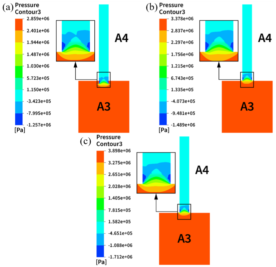
The steady-state pressure field distribution for various outlet pipe diameters under constant inlet pressure is illustrated in Figure 14. The numerical simulation results indicate that the flow channel with a 4 mm diameter exhibits a more uniform pressure gradient distribution in the main flow region, with the pressure at the outlet connection section A3 being 2.739 MPa. This is a reduction of 29.7% and 29.5% compared to the 2 and 1 mm diameters. Notably, the systems with 1 and 2 mm diameters maintain the pressure of 3.8 MPa in the flow development section, with significant pressure drop primarily in the nozzle contraction section. This is attributed to the acceleration effect caused by the abrupt change in the cross-sectional area of the flow channel.

Pressure contours for different outlet pipe diameters: (a) d4 = 1 mm, (b) d4 = 2 mm, and (c) d4 = 4 mm.
Under constant inlet pressure conditions, the velocity cloud maps (Figure 15) of different outlet pipe diameters (4, 2, 1 mm) were analyzed and compared. As the pipe diameter decreases from 4 to 1 mm, the maximum velocity increases from 81.89 to 97.21 m/s, representing an increase of 18.7%. However, the 4 mm diameter configuration exhibited superior uniformity in outlet velocity distribution, achieving full-domain velocity homogenization and outperforming both 2 and 1 mm systems. This behavior aligns closely with theoretical predictions from the continuity equation for incompressible fluids, where larger diameters suppress velocity gradients and enhance flow stability.

Velocity contours for different outlet pipe diameters: (a) d4 = 1 mm, (b) d4 = 2 mm, and (c) d4 = 4 mm.
Under constant inlet pressure, the turbulent kinetic energy (TKE) distributions for outlet pipe diameters of 1 and 2 mm were simulated and plotted in Figure 16. For the 2 mm pipe, TKE accumulated spatially with a maximum near-wall value of 71.1 m2/s2, which was 33.5% higher than the 53.27 m2/s2 observed in the 1 mm pipe. This indicates the 2 mm pipe system has higher turbulence intensity and momentum transport efficiency. In contrast, the 1 mm pipe showed relatively lower TKE. Overall, pipe diameter significantly affects turbulence characteristics.

TKE distribution for different outlet diameters: (a) d4 = 1 mm and (b) d4 = 2 mm.
With the inlet diameter fixed at 7 mm, the inlet pressure rose linearly from 2.8 to 3.9 MPa as the motor thrust increased stepwise from 110 to 150 N. Figure 17 presents the corresponding pressure distribution. When the inlet pressure rose, the pressure gradient distribution pattern remained highly similar, and the outlet pressure was strongly positively correlated with the inlet pressure. 23 These findings confirm the dominant role of inlet pressure in governing the global pressure field and provide a theoretical basis for the design of closed-loop control systems based on thrust feedback.
Pressure contours under different inlet pressures: (a) p1 = 2.8 MPa, (b) p1 = 3.4 MPa, and (c) p1 = 3.9 MPa.
An increase in the inlet pressure significantly enhances the outlet velocity is indicated in Figure 18. Specifically, when the pressure rises from 2.8 to 3.9 MPa, the maximum velocity increases from 82.6 to 97.2 m/s, resulting in an increase of 17.6%. Longitudinal comparisons reveal that velocity peaks are all observed at the center of the pipe outlet under various pressure conditions. The velocity gradient at the outlet intensifies with increasing inlet pressure, indicating that the jet impact effect is more significant under high pressure conditions.

Velocity contours under different inlet pressures: (a) p1 = 2.8 MPa, (b) p1 = 3.4 MPa, and (c) p1 = 3.9 MPa.
The velocity streamlines based on different inlet pressures is shown in Figure 19. For the 2.8 MPa case (Figure 19(a)), the velocity ranges from 2 to 82.6 m/s, whereas the 3.9 MPa condition (Figure 19(b)) exhibits an expanded range of 0–97.2 m/s. The smooth streamlines in both cases confirm unimpeded fluid transport throughout the pipeline.

Flow streamlines under different inlet pressures: (a) p1 = 2.8 MPa and (b) p1 = 3.9 MPa.
Motor and cleaning machine test
Prototyping and testbed construction
The optimization design was implemented through precision machining, manufacturing, assembly, and debugging processes. The final prototype measured 245 mm × 150 mm × 100 mm with a net weight of 1.5 kg, with its practical internal architecture detailed in Figure 20.
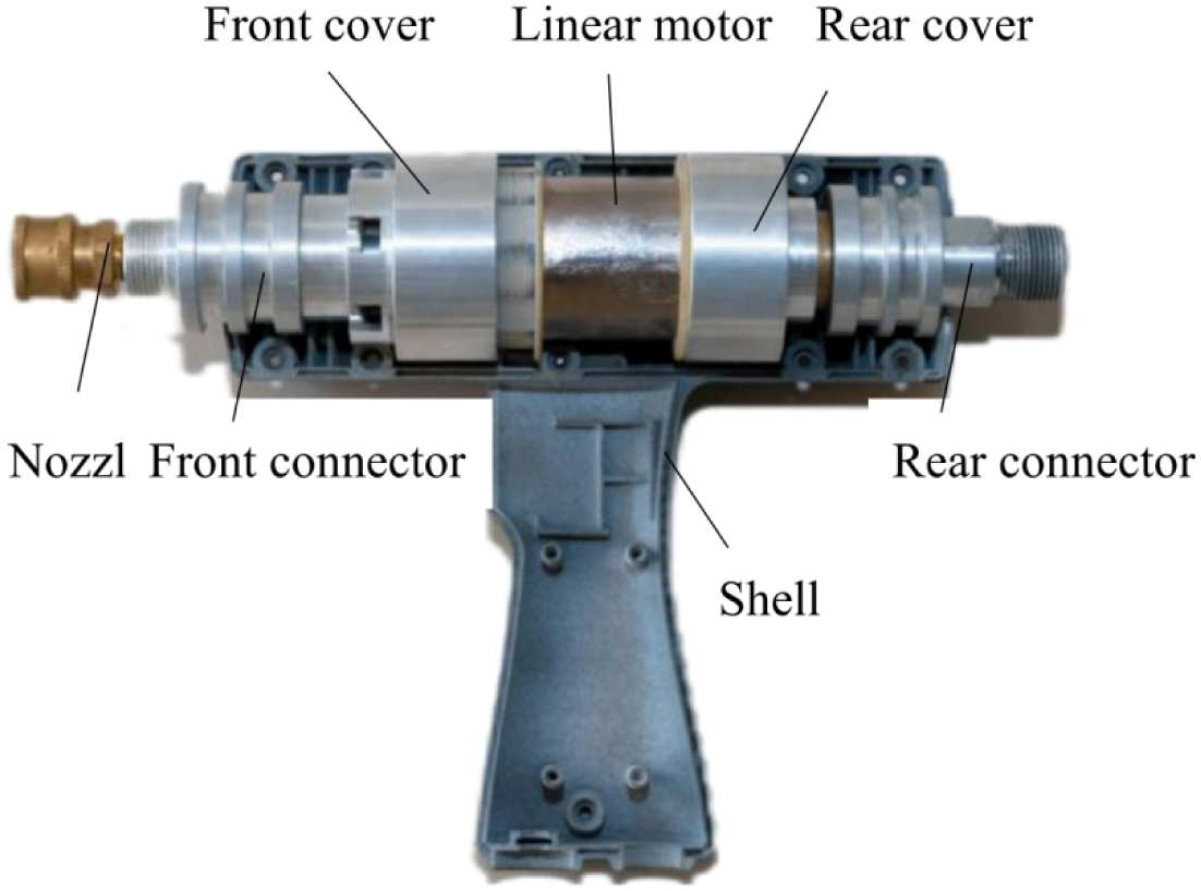
Internal structure of cleaning machine.
A dedicated linear motor testbed was constructed for performance evaluation (Figure 21), comprising three subsystems: (1) core components, (2) sensing units (E3X-NA11 displacement sensor; JC2202 thrust sensor), and (3) auxiliary modules (SIMATIC S7 PLC controller, 24 V DC power supply). The motor has a rated current of 2 A, a rated power of 450 W, and a rated thrust of 150 N. Real-time data acquisition was implemented through integrated sensor-processor synchronization.

Linear motor test stand.
Motor performance test
Maximum thrust
The motor was rigidly mounted on the test platform, coupled with a real-time thrust sensor. The input current was changed by adjustable resistor to detect different thrusts of the motor. Data recording began when the thrust reached 10 N. After several measurements, it was found that the motor thrust reached peak performance when the input current was 2 A.
Travel distance
The displacement sensor was used to measure the moving distance. The probe of sensor was placed in the direction of the linear motorized actuator. As the actuator was running, the sensor collected position signals and transmitted them to the controller for processing. The processed signals were then sent to the display to obtain the displacement distance.
Running speed
The cleaning performance of the cleaning machine was closely related to the cleaning pressure and speed, and there was a process of acceleration and deceleration when the motor was running. Therefore, the speed average value was selected as the speed acquisition zone when the motor operated steadily and the thrust reached its maximum.
Safety buffer margin
When the mover of the linear motor approached the end sensor, the motor stopped. The displacement between the mover and the end of the stroke at this moment was defined as the buffer margin to ensure the safety of the motor.
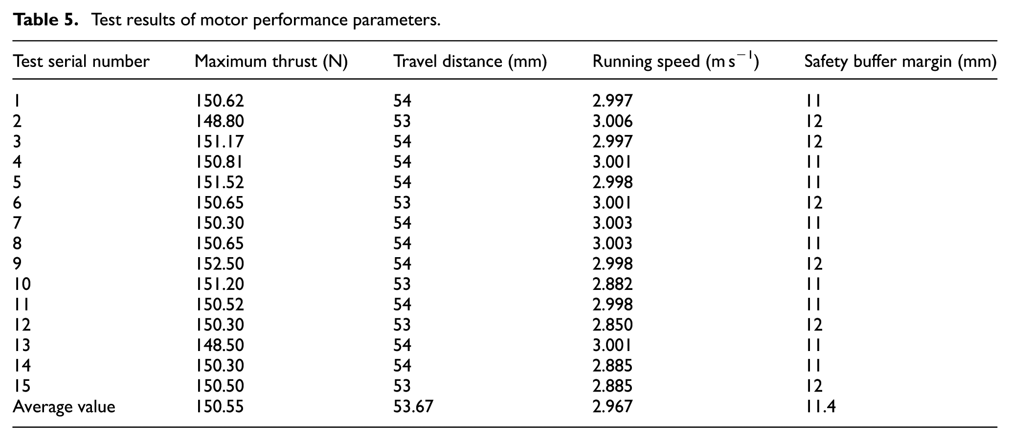
Motor performance tests were consecutively carried out seven times based on the linear motor test platform, and the average values were calculated, as exhibited in Table 5. The average maximum thrust of the motor was 150.55 N, which is superior to similar mainstream motor products. Additionally, the operating speed of 3 m/s exceeded that of most cleaning machine motors available on the market.
Test results of motor performance parameters.
To facilitate a comparison between experimental and simulated results, the input current was adjusted to measure the corresponding thrust values. As shown in Figure 22, the test results are very close to the simulation data, with minimal error. The motor thrust reached 150 N with a peak relative error of 3.5% under 2 A excitation. The error mainly originated from the unconsidered friction in the simulation process and the deviation in the installation position of the sensor.

Comparison of linear motor thrust under simulated and test conditions.
Cleaning effect test
To ensure cleaning effectiveness, the cleaned surface must be inspected. As there is currently no specific national standard in China for judging stain area, the core concept of “control by particle size classification” from the automotive industry standard VDA 19 is referenced. Accordingly, a stain area of less than 2 mm2 (equivalent to a particle size of 1.6 mm) is defined as a cleaned area. Cleaning efficiency is represented by E, thus the cleaning rate formula can be derived.

Where,
The cleaning efficiency of the prototype was quantitatively assessed using equation (14). The experiment was conducted in an automotive cleaning workshop (AC 220 V/50 Hz, 450 W power input). With the nozzle angle and water pressure held constant, three critical parameters for cleaning effectiveness—outlet pipe diameter, motor thrust, and water temperature—were identified based on prior simulations and empirical data. 24 Based on previous fluid simulation results, the outlet pipe diameters were set at 1, 2, and 4 mm. Motor thrust levels were selected as 110, 130, and 150 N. The water temperature was set at 30°C, 40°C, and 50°C. As shown in Table 6.
Factor level of orthogonal experiment.

The orthogonal experiment, designed with nine groups of three replicates each, was conducted as detailed in Table 7. The results showed that the cleaning efficiency of the cleaning machine ranged from 81% to 95%.
Test protocol and results.
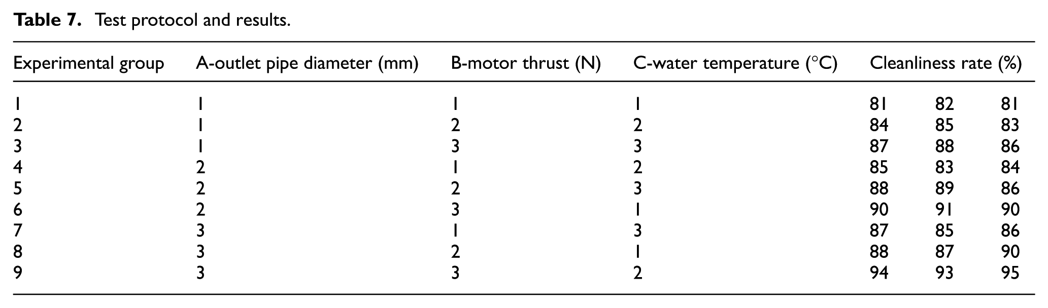
According to the results of the orthogonal test, the range analysis table (Table 8) shows that motor thrust has the greatest influence on cleaning efficiency, followed by outlet pipe diameter and water temperature, in that order.
Range analysis table.

The range analysis of orthogonal experimental results (Table 6) revealed motor thrust as the predominant factor affecting cleaning efficacy, with subsequent influences from outlet pipe diameter and water temperature in descending order of significance.
To identify the optimal cleaning parameters, further analysis of variance was conducted. The significance results indicated that motor thrust (B) had the greatest impact on cleaning efficacy, followed by outlet pipe diameter (A) and water temperature (C). The optimal parameter combination was identified as B3A3C2 (150 N thrust, 4 mm diameter, 40°C). Repeated cleaning trials under this configuration demonstrated consistent noise levels at 50 dB, as measured in a semi-anechoic lab with ambient noise below 15 dB, in compliance with the ISO 3744 international standard, using a calibrated TES1350A sound level meter. To ensure data reliability, repeated tests were conducted no less than 20 times at different intervals, with results consistently falling within the range of 50 ± 1.5 dB.
A quantitative comparison was further conducted between the novel linear-motor-driven cleaning machine and traditional plunger and swash-plate-pump architectures, as in Table 9. The linear-motor platform exhibited pronounced advantages in structural compactness, noise level, and energy consumption. Its volume of 245 mm × 150 mm × 100 mm is substantially smaller than that of traditional pumps; the operating sound pressure level is approximately 50 dB, markedly lower than the 90 dB of plunger pumps and 75 dB of swash-plate pumps; and its specific energy consumption is 0.45 kWh, representing a significant reduction relative to the 1.3–1.4 kWh required by conventional units. The current prototype has a rated pressure of 39 bar. Mainstream commercial products have 60–75 bar. However, its low noise, low energy use, and small size are very attractive. It is well-suited for homes, labs, and other noise-sensitive cleaning tasks.
Performance parameter comparison between linear motor-based cleaning machines and traditional pumps.

Conclusions and outlook
This study proposes a novel design for a linear motor cleaning machine based on TRIZ theory. A thrust model for the linear motor and a fluid injection model were established. Simulations were conducted to analyze the effects of current on magnetic flux and thrust, as well as the relationship between pressure and flow velocity. A prototype was then fabricated and tested to validate the simulation results. The main findings are as follows:
(1) Six preliminary structural optimization strategies for the cleaning machine were proposed using TRIZ substance-field models and conflict resolution theory. The dynamic and coordinated evolution laws were applied to select a linear motor as the power unit. This motor, composed of alternately arranged permanent magnets and multi-parallel coils, achieves innovative structural optimization of the cleaning machine.
(2) The traditional layout of separate water gun and power unit was changed by integrating the linear motor into the gun body, resulting in a compact design that enhances portability. Compared with conventional high-pressure pump cleaning machines, the noise level was reduced from 90 to 50 dB.
(3) The cooling of the linear motor was innovatively achieved by the water flow in the pipeline of cleaning machine. This structure enhances the stability of motor operation, extends the single-run time, and increases the overall service life.
(4) Experimental validation revealed a maximum thrust of 150.55 N under 2 A excitation current, showing close agreement with simulation results (3.5% deviation from simulated values). Significance ranking via ANOVA identified motor thrust as the predominant factor, followed by outlet diameter and water temperature in descending order of influence. The B3A3C2 configuration (150 N, 4 mm, 40°C) achieved optimal cleaning performance.
Furthermore, the thermal stability and long-term durability of the cleaning system remain to be optimized. To this end, key components will be monitored for temperature rise by means of infrared thermography, and continuous fatigue testing will be conducted on an accelerated-life test rig to evaluate reliability and provide a basis for structural improvement.
Footnotes
Handling Editor: Chenhui Liang
Author contributions
Conceptualization, methodology, software, and writing—original draft preparation, B.Z.; validation, investigation and formal analysis, X.L.; visualization, resources, and data curation, H.W.; writing—review, editing, supervision, C.F. All authors have read and agreed to the published version of the manuscript.
Funding
The authors disclosed receipt of the following financial support for the research, authorship, and/or publication of this article: This research was funded by Qinglan Project for Colleges and Universities in Jiangsu Province (Grant No. Teacher Su’s Letter [2024] No. 14), and supported by the Fundamental Research Project for Universities in Jiangsu Province (Grant No. 22KJB150038).
Declaration of conflicting interests
The authors declared no potential conflicts of interest with respect to the research, authorship, and/or publication of this article.