
Abstract
A high thrust force bi-double-sided permanent magnet linear synchronous motor used in gantry-type five-axis machining center is designed and its performance was tested in this article. This motor is the subproject of Chinese National Science and Technology Major Project named as “development of domestic large thrust linear motor used in high-speed gantry-type five-axis machining center project” jointly participated by enterprises and universities. According to the requirement of the application environment and motor performance parameters, the linear motor’s basic dimensions, form of windings, and magnet arrangement are preliminarily specified through theoretical analysis and calculation. To verify the correctness of the result of the calculation, the finite element model of the motor is established. The static and dynamic characteristics of the motor are studied and analyzed through the finite element method, and the initial scheme is revised. The prototype of the motor is manufactured based on the final revised structure parameters, and the performance of the motor is fully tested using the evaluation platform for direct-drive motor component. Experimental test results meet the design requirements and show the effectiveness of design method and process.
Keywords
Introduction
High-speed machining (HSM) is the main feature and one of the development directions of modern advanced manufacturing technology. It has the advantages of less generated heat, low cutting force and small deformation for the parts during high-speed cutting. This technology can improve the parts’ machining accuracy and surface quality as well as the production efficiency, thus it is widely applied in aerospace, mold manufacturing, and other fields. Rapid feed system is where high-speed ball screw and linear motion motor are commonly used as one of the major means to realize the high-speed milling. However, the process ability and scope of application of high-speed ball screw are limited because of the existence of decelerating mechanism and other intermediate transport segments, it is usually suitable for the situation of moderate or light load, middle or low speed (10–40 m/min), and moderate or small accelerometer (0.5–1.0 g), so there are still certain disparities to meet the requirements of modern HSM. 1
In factory automation and office automation, rotary motors are usually used in their operations even though in driving the linear motion load. In this case, the intermediate gears, screws, bearings, or crank shafts are used to convert the rotational motion into the linear motion which will cause the mechanical losses and affect the performance of the motor operation.
Linear motor can drive a linear motion load without intermediate gears, screws, or crank shafts. Linear synchronous motor (LSM) is one of the types of linear motor, and it has a very wide range of applications from the small application (i.e. industrials automation) to large application (i.e. maglev transportation).2,3 This technology obviously has higher precision, faster speed, and better dynamic performance than the traditional motor, as well as higher location and tracking precision. The maximum feed speed and acceleration can reach 90–180 m/min and 2–10 g. Also, the positioning precision is increased due to simplified system dynamics. The study and application of linear motor feed system has been done in the many fields, such as high-speed linear reciprocating unit, precision feeding system, super finishing, and strict space requirement for some parts of high-performance functional unit on the numerical control (NC) machine tool. The remarkable effect has been verified in practice.4,5
Although the linear motor has been used for its ability to drive directly without the use of a mechanical converter in linear motion, it still has a number of disadvantages, such as the end effects, normal force, and low efficiency. In order to overcome these inconveniences, a new type of linear motor that is called permanent magnet double-sided LSM with perpendicular arrangement (perpendicular PMDLSM) is designed to weaken its negative effects.6,7 In Kim et al., 6 a new type of linear motor was proposed—perpendicular PMDLSM which has many advantages, such as balanced normal force, easy manufacture, and simple maintenance. In Lu et al., 7 the different PMLSM structures are investigated in detail. For typical slot–pole combinations 12/11 and 12/10, eight feasible structures are described, which adopt single-sided or double-sided and all-teeth wounded winding or alternate-teeth wounded winding. Also, many researches have been conducted to find out the ways to overcome drawbacks of the PMLSM.
In this article, a large thrust force bi-double-sided linear motor used in a high-speed gantry-type five-axis machining center is studied and designed, and the performance parameters of the linear motor are shown in Table 1.
Performance parameters.
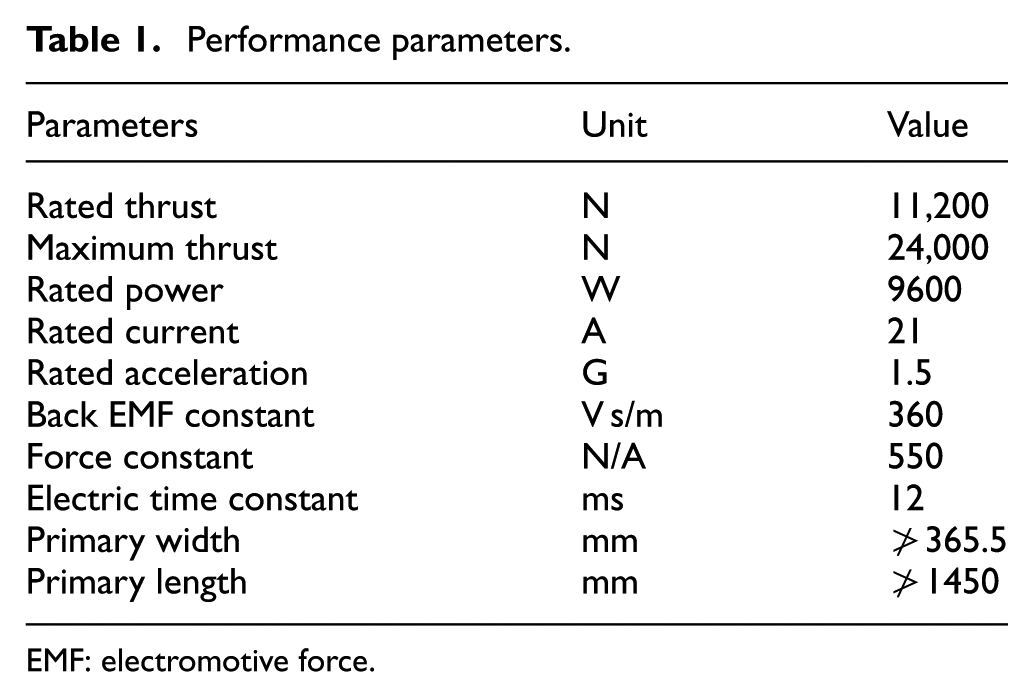
EMF: electromotive force.
According to the requirements of the geometry size, the related performance parameters and the characteristics of the different types of PMLSMs, the double U-type structure are set as the main scheme of this linear motor. The structure of unequal teeth tips width and alternate winding is used in the secondary armature winding and the permanent magnets (PMs) are manufactured and assembled with an appropriate skewing angle in this motor with the 12/10 similar pole and slot number.
The main requirements of this motor include geometric dimensions, and the electromechanical system ratings have been shown in Table 1. The specified system performance indexes, such as velocity stability (≤5%), static friction force, thrust stability (≤5%), positioning accuracy (≤10 µm), repeat positioning accuracy (≤5 µm), runout variation (≤1.5 µm), and step response in different test conditions, are also the core bases for the motor design. The linear motor can basically meet the design requirements through theoretical calculation, finite element analysis (FEA), and experimental confirmation.
Design of bi-double-sided PMDLSM
Besides the common structure of plate-type linear motor, the typical structures of PMLSM are cylindrical type and U-form. The plate-type linear motor in operation has the disadvantage that the attractive force between PMs and iron core causes the increase in the friction resistance which leads to the increase in control difficulty and may affect the accuracy of the control system. Therefore, the double-sided structure is selected, as shown in Figure 1. This scheme makes the attractive forces between PM and iron core offset each other and overcomes the shortcomings of the plate-type linear motor.6,8,9 In Zheng et al., 9 the characteristics of detent force and propulsion force of PMLSM are investigated under different motor topology structures, such as different PMLSM topologies, different mover topologies, and different armature core topologies.

Basic structure of U-type PMLSM.
To meet the requirements of geometry sizes and performance of the PMLSM application system, the preliminary design structural scheme is shown in Figure 2. The mover (primary windings) is armature winding and the stator (secondary) is PM. In fact, this motor includes two U-type linear motors (it amounts to four linear motors with perpendicular arrangement), such a design scheme not only decreases the longitudinal dimension and improves the static and dynamic performances of the linear motor, such as thrust force, speed, acceleration, and so on, but also reserves the advantages of U-type linear motor.

Structure design of the linear motor.
In conclusion, some new technologies in our PMLSM are used during the design process to ensure that the PMLSM can meet the design requirements. The gravity effect of the motor can be reduced by the perpendicular arrangement of the motor. The arrangement of U-type has been used to offset the attractive forces between PM and iron core. The skewing arrangement of PM can reduce the thrust fluctuation and other side effects. The bi-double-sided arrangement can decrease geometric dimension and improve operation performance. The test results also show the effectiveness of these technologies.
Design of the size of linear motor
For the design of the linear motor, the rotary motor’s design method provides a referenced way. 10 The main dimensions of the motor are initially determined by the following formula in Zhao. 10

where L is the longitudinal length of the linear motor;
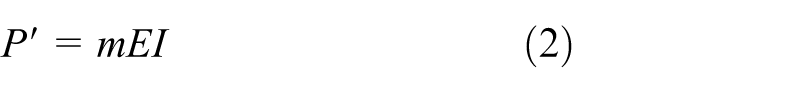
where m, I, and E are the phase number, phase current, and armature winding’s phase electromotive force (EMF) of the motor, respectively

where f is the current frequency of the armature winding, N is the series turns number of per phase of armature winding, and


where
In equation (1),
The value of utilization factor, which has direct impact on the effective material consumption of the motor, is determined by A and
Design of the magnetic steel
The determination of magnetic steel size is a major factor during the motor structure design. The design contents include the length, height, and width of the PMs which are symbolized as
To determine the magnetic steel size,


where
Nd-Fe-B (NdFeB42SH) PM is used in this motor. In the case of considering air gap flux density, thrust ripple, power factor, stable current, and dynamic performance and combined with the calculated results, the magnet height is 5.5 mm, the distance between the PMs is 2 mm, and the remanence is 1.2 T. Smaller thrust fluctuation can be achieved by arranging magnets with slope arrangement, and the skew angle of the magnet is 4° for this motor. 6
Design of the winding form
There is not a systematic and mature method yet for the design of the PMLSM’s primary armature winding, so the embedding double-layer winding method for rotary electric motor is often used as a reference. In practice, this embedding process is always complex and may also lead to the problems such as heat dissipation issues because of larger coil space factor and asymmetrical parameters of the three-phase winding. Therefore, the unequal teeth tip width and alternate winding approaches are adopted in the practical design.12,13 In Zhu et al., 13 an optimal design of a double-sided slotted iron core–type PMLSM used for ropeless elevator system is investigated. To obtain the optimal structure, the combination of response surface methodology (RSM) and two-dimensional (2D) FEA is utilized to investigate the PMLSM characteristics.
For the design of the stator, the similar pole slot number with 10/12 can realize unequal teeth tip width of the armature winding.7,14 Unequal teeth tip width and inclined magnets can improve the winding pitch coefficient and the winding coefficient which lead to the increase in the torque density and elimination of the torque ripple, effectively. The similar amount of poles and slots can reduce complexity during the machining process. 15
The alternate winding for unequal teeth tip width refers to only the big teeth that have coils and the small teeth that do not have coils, so it is called alternate winding. This winding type has the same number of turns and the same slot space factor. The similar number of slots–poles has the advantage of better processing manufacturability.16,17
The U-type single-layer winding and cogging structure of the U-type linear motor are shown in Figure 3. The number of slots and magnetic poles are 36 and 30, respectively. Three-phase Y-type winding connection is adopted in the PMLSM.

Winding and cogging structure.
Through analysis of the structure dimension, the size of magnetic steel, the form of winding, the geometry size in practical application, and the requirements of its static and dynamic characteristics, the final parameters are obtained and shown in Table 2.
Design parameters of the linear motor.

PM: permanent magnet.
FEA
In order to verify and analyze the basic properties of the designed motor, the finite element model has been built, and the basic characteristics of the linear have been analyzed. The 2D finite element method (FEM) analysis with Ansoft Maxwell 12 is used for saving the calculation time based on the following simplifying assumptions: 18
The exterior magnetic field of motor is neglected.
The current density in the conductor is evenly distributed.
The nonlinearity and eddying effect of the iron core are considered through the curve of magnetization and damage curve, with no view of the magnetic hysteresis effect.
Taking into account the actual operation condition, the even symmetry boundary condition is adopted to assume the primary infinitely. 19
The motor geometric model is created according to the results of the previous design, and the materials used in the motor are also defined correspondingly. When the linear motor is analyzed, the balloon boundary can be applied to the motor, and the load is excited for the electric current with the three phases being the same.
In the simulation experiment, the motor speed is 1 m/s under nonloaded condition. The simulation results include flux distribution, flux density, thrust ripple, flux linkage, back EMF, and so on.
The finite element results are shown in Figure 4. Figure 4(a) shows the distribution of magnetic induction lines and magnetic flux density, and they are evenly distributed and change with the phase sequence correctly. Detent force, as one of the principal of thrust ripples, is also a primary factor to evaluate the PMLSM, 20 and the detent force ripple under nonloaded condition is shown in Figure 4(b). There are many kinds of thrust fluctuation factors because of the intrinsic characteristic of linear motor, and the curve shows that the ripple changes in a narrower range under no-load state when the motor is in steady-state operation, and the subsequent control measures can be taken to solve this problem. As shown in Figure 4(c), the flux linkage waveform is sinusoidal, and it indicates that the magnetic circuit design is reasonable. The EMF is an important parameter for the analysis and calculation of the motor performance, such as thrust ripple, maximum speed, and rated current. For the 30-pole 36-slot unit PMLSM with double side structure, the nonload back EMF waveform is shown in Figure 4(d). The higher harmonics, caused by the special structure of the linear motor and the existence of longitudinal end effect, cogging effect, leakage of flux under nonloaded condition, and the pole arc coefficient without optimization are not eliminated effectively, so the back EMF waveform is just close to the ideal sinusoidal, and the sum of the three back EMF values may not be zero, which are exactly consistent with the actual analysis under this condition.
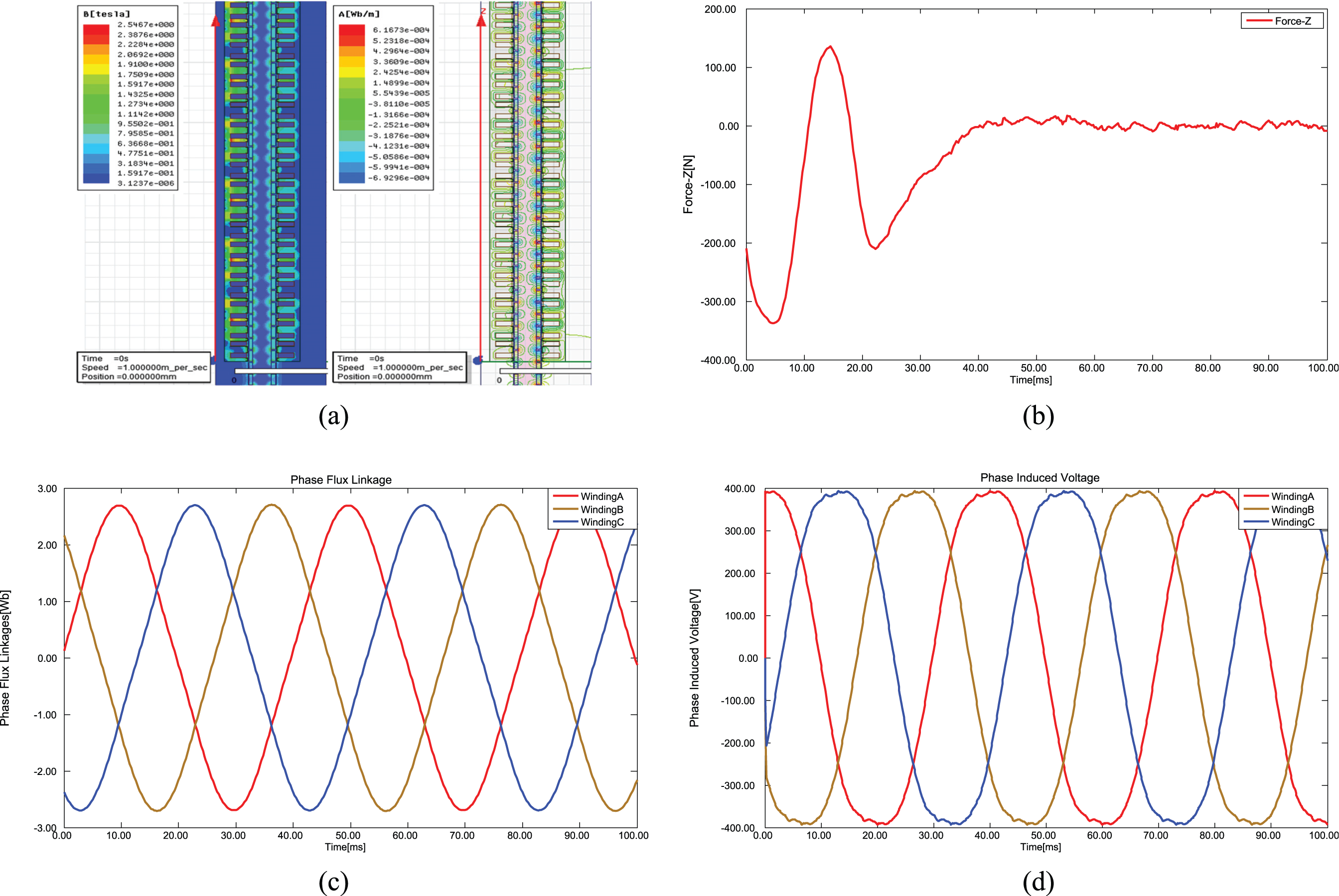
Finite element simulation under nonloaded condition: (a) distribution of magnetic induction lines and magnetic flux density, (b) detent force ripple, (c) flux linkage waveform, and (d) nonload back EMF.
Performance test
The linear motor is manufactured based on theoretical analysis, optimal design, and finite element simulation analysis. The primary section is made up of two parallel double-sided mounting panels which are cast from ZG35 with galvanizing after surface manufacturing process: the length, width, and height are 1.4, 0.36, and 0.22 m, respectively. Aluminum cast water cooling plate embedded with aluminum tube is installed between the primary winding and the mounting panel to cool the primary windings.
The secondary double-sided plate cast from ZG35 and galvanizing is at the bottom of the linear motor. The total length is 7.48 m with six sections for the convenience of assembly and transportation. Among them, each of the same five sections’ length is 1.32 m, and the rest is 0.88 m. The width of each selection is 0.26 m, and the height is 0.17 m. The permanent magnetic material is NdFeB42SH, N pole magnets and S pole magnets are alternately stuck on the secondary surface and make both sides of the same plate with the opposite polarity. The magnet steels on the same side are partitioned with aluminum sheet after sticking firmly and making them as a whole by infusing with epoxy resins. Figure 5 shows the actual motor.

Actual motor: (a) secondary winding, (b) primary magnetic steel, and (c) and (d) practical motor.
Combined with the needs of users, the actual performance of the linear motor was further tested and verified before it comes into service. 21 The test system is shown in Figure 6. The direct driving component test evaluation platform, which was completed by the laboratory, is taken as the performance test system. The main components of the test system includes a loading linear motor which provides resist force to simulate the work condition for the test motor and a mounting mechanism to fix the test motor. These two motors are connected together through a force sensor. The test software and evaluation system of machine tool application is made to record the test results consisting of accuracy, speed, running stability, load change range, and so on. The platform satisfies the motor test requirements with its thrust force test range being more than 15,000 N, and the speed over 3 m/s.
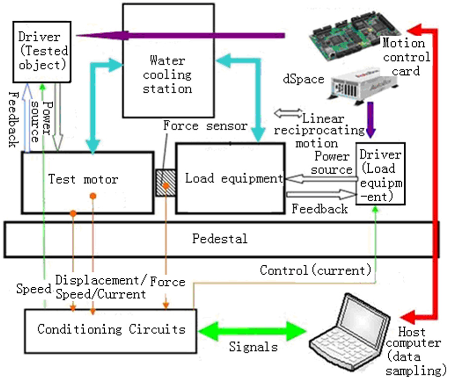
Performance test system.
A simplified servo control scheme is proposed because this motor would be used in a NC machine tool, as previously mentioned, in a gantry-type five-axis machining center. The motion controller or digital controller (system), which has three basic functions as motion planning, producing motion trajectory and motion controlling, is the core part for a direct-drive servo system. Wherein the motion control is directly related to the servo system which fulfills the control of velocity feedforward (also known as speed compensation) and acceleration feedforward (also known as the current compensation or force compensation). A PMAC (programmable multi-axes controller) is used as the controller in this system, and the test control loop scheme is shown in Figure 7. It is noted that the detail for the control loop design is not provided here due to the paper space limit, and the future research will be further studied to improve the control performance of the system.

Proposed complete control system.
The test contents include velocity stability, static friction force, thrust stability, positioning accuracy, step response, and so on. The steady-state error is 2.09% and 3.86% under the speed of 4 and 10 m/min, respectively, and the test results are shown in Figure 8(a) and (b). The static friction force is the minimum thrust to make the motor run, and its value is 533.8 N. The thrust stability refers to the NC system output stable specified thrust, and the thrust ripple and the current fluctuation can be tested by force sensor and NC system, respectively. Two cases, the thrust of 560 N and the current of 2.1 A and the thrust of 1120 N and the current of 4.2 A, have been tested, and the servo current fluctuation and the thrust ripple are 1.4% and 3.0% and 2.1% and 1.6%, respectively. The step response test with test speed of 1.8 m/min is shown in Figure 8(d). The step response performances are improved by adjusting the control parameters, and the rise time is 3.4 ms, and the maximum overshoot is 62%. The theoretical and actual thrust forces to the current of the linear motor are tested, and the error is provided at the same time, as shown in Figure 8(c).

Test result: (a) 10 m/min, (b) 4 m/min, (c) thrust force, and (d) step response.
Positioning accuracy was tested in both cases, without load and with load, unidirectional and bidirectional movement. The example of test result is shown in Figure 9.

Test result of positioning error.
The Chinese national standard GB/T 17421.2 and ISO 230-2 are used in the positioning error test and analysis. No-load unidirectional positioning accuracy is 9.8 µm, re-orientation accuracy achieves 4.8 µm, and the runout variation is 1.5 µm. No-load bidirectional positioning accuracy is 12.0 µm, re-orientation accuracy achieves 7.6 µm, and the runout variation is 1.5 µm. Unidirectional positioning accuracy with load of 1800 N is 7.8 µm, re-orientation accuracy is 4.2 µm, and the runout variation is 0.3 µm. Bidirectional positioning accuracy with load of 1800 N is 10.1 µm, re-orientation accuracy is 4.7 µm, and the runout variation is 0.3 µm.
The above test results meet the requirements of the performance which the user demands to a certain extent. However, there are relatively large errors, especially for the thrust force. Through analysis of the system, it is believed that the following aspects might be the main causes for error. First, no correction for current detection loop parameters and power out parameters may lead to measurement errors. Second, inaccurate phase could result in inaccurate test result, and this may be the leading role for error. Third, thrust sensor with LabVIEW data acquisition and the average result reading result also can produce some error. The future work is to further study the causes of error and the improvement for the motor and control system.
Conclusion
Direct-drive feed system in the high-speed computer numerical control (CNC) machine tools with linear motor has a broad market demand and good application prospect. There is no mature theoretical and technological basis for the design and manufacturing of linear motor due to the short development time in this field. Because of the linear motor’s inherent structure and electromagnetic characteristics, taking the experienced design method of rotary motor as a reference is still the main means for linear motor designing.
In this article, a design scheme of large thrust linear motor applied in NC machine tools is proposed. The linear motor has been manufactured based on the geometrical size and performance parameters requirement of the application system. The bi-double-sided structure is selected as the main scheme of the motor, and unequal teeth tip width, alternate winding approaches, oblique magnets, and similar pole and slot number are adopted in the practical design. In the design process, the motor’s basic size, the layout of magnetic steel, and the connection forms of windings are obtained through theoretical analysis first. The finite element simulation analysis has also been used as a measurement to analyze the accuracy of the structure design. At last, the prototype motor is tested in a test system, and the results prove that the system meets the design requirements of the user. At the same time, the research process and result in this article provide a reference way for the study of related areas.
Footnotes
Academic Editor: Tian Han
Declaration of conflicting interests
The author(s) declared no potential conflicts of interest with respect to the research, authorship, and/or publication of this article.
Funding
The author(s) disclosed receipt of the following financial support for the research, authorship, and/or publication of this article: This research is funded by National Natural Science Foundation Project in China, grant nos 51275053, 51405026, and 51575056. This research is supported by Collaborative Innovation Center of Electric Vehicles in Beijing, China.