
Abstract
High material removal rate, high resolution and reproducibility of micromilling make it a suitable process for making microfeatures on different materials. However, existence of unwanted protrusions or surface irregularities on the machined surface known as burrs demands some post-processing to make it qualify for end use. In addition, clogging of materials on the flute surface increases the effective edge radius and tool loading during polymer machining. In the present work, a new strategy is demonstrated for simultaneous deburring of microchannel and cleaning of cutting tool during micromilling of polymethyl methacrylate. The performance of the process has been further evaluated by milling of microchannels in oxygen-free high conductivity copper workpiece. Burr formation, surface roughness and tool loading have been found to be significantly reduced by using the proposed method. A theoretical study of the process has also been carried out to understand the mechanism of the proposed method.
Introduction
The shift from silicon- or glass-based platforms to a polymer-based platform made a high impact on microfluidic devices. Certain characteristics of the polymers including chemical inertness, transparency, structural stiffness and critical surface tension popularized its use in Lab on-chip applications. For example, PMMA (polymethyl methacrylate) is successively used to make capillary electrophoresis microchips for separation of double-stranded DNA fragments or other micro total analytical systems (TAS).1,2 DNA amplification devices and microfluidic mixers are fabricated using polycarbonates (PC); 3 polystyrene is effectively used as the substrate material for cell growth studies. 4 However, successful commercial microfluidic devices are less in number due to the absence of an effective single step process for fabrication of those devices. There are so many manufacturing processes which are proven for fabricating microfeatures on polymer materials. This includes injection moulding, 5 laser machining, 6 ultrasonic welding, 7 additive manufacturing, 8 plasma etching, 9 lithographic processes 10 and embossing techniques. 11 Among these, most of the processes demand some kind of secondary machining operation for making it into a usable form. Others need high capital cost and special arrangements like clean room environment, vacuum chambers and new power infrastructures which increases the total manufacturing cost and energy requirement. Temperature-dependent processes like laser ablation create irregular polymer compositions and non-uniform surfaces in the microchannels due to material re-deposition and solidification. Chemical processes like etching deal with some hazardous chemical reagents. So to reduce the total cost of production and energy usage for fabrication of microfluidic devices, we need a cost-effective process which is capable of fabricating complex shapes in polymer materials with small lead time and needs comparatively less capital investment. 12
Conventional micromachining processes proved its capability of machining microparts of complex designs with a high degree of reproducibility. Flexibility is another aspect which makes this process most effective regarding adapting the frequent variations in the component design. Machinability studies of polymer materials have been performed by a number of researchers. Filiz et al. 13 analysed the effect of machining parameters on polymer materials (polylactic acid (PLA) and PMMA) during micromilling and concluded that spindle speed and feed rate are the most important parameters that affect the surface quality and machining forces but the relationships differ from conventional machining conditions. Machinability studies on polypropylene 14 composites revealed that the reinforced polypropylene has lesser micromachinability compared to the un-reinforced polymer. Micromilling can be used for making the micromoulds for injection moulding or can be used directly on polymer blanks to create microchannels. The latter one has the advantage of lesser processing time and flexibility. Researchers have used micromilling extensively for fabrication of microfluidic devices including Kit-On-A-Lid-Assays (KOALA) in which multiple slides fabricated by micromilling can be combined for fluid delivery, 15 cell capture devices with oil and aqueous interfaces, 16 and devices for microenvironmental studies on primary foetal testis cells. 17 The machinability studies on polymer materials revealed that the elastomers like PDMS (polydimethylsiloxane) are difficult to process using micromilling. 12 PMMA has higher machinability compared to PDMS, and PMMA microfluidic devices have the advantage of having least hydrophobic nature 18 compared to other polymers. Superior physiochemical properties like minimum levels of autofluorescence of PMMA makes the process of fluorescence detection easy. 2 PMMA components can be machined to a nanometric level surface roughness by controlling the feed and cutting orientation. 19 Being cheap, PMMA can be the perfect material for affordable microfluidic devices.1,2,20 Selecting PMMA as workpiece material and micromilling as the manufacturing method, microfluidic devices can be manufactured in the least amount of time with minimum cost. However, all the advantages like least lead time, high resolution, reproducibility and flexibility are not enough to propose micromilling as a solution to current problems faced by polymer micromanufacturing industries. Micromachined channels or surfaces often fail to achieve the required quality standards for microfluidic devices. Therefore, it always demands some post-processing technique to improve the surface quality of the machined components.
Burr formation is an inevitable phenomenon in micromachining. Unlike in the case of macromachining, here the surface irregularities will be comparable to the size of the microfeatures in part. The cutting edge radius of the tool is comparable to the un-deformed chip thickness so that instead of cutting, ploughing of material will become predominant. 21 Different types of the burr and mechanics of burr formation in different types of polymers are studied by Ervine et al. 22 They have consolidated the machining experiments to state that the ratio of burr size to tool diameter taken after the machining of similar parts in the micro- and macroregime are showing significant differences. This ratio is in the range of 0.01–0.25 in the case of machining with tools with a diameter greater than 1 mm and varies in the range of 0.02–0.65 in the case of tools with diameters in micro range. So, micromilling alone cannot be presented as a single-step process for fabrication of polymer microfluidic devices. Different experimental investigations propose different kinds of solutions. One of them is to control the machining parameters like cutting speed and feed and applying machining strategies like controlling exit order sequence (EOS) by varying tool path in end milling. 23 An alternative solution is to use some deburring operations like ultrasonic peening or micro electric discharge machining (EDM) in the machined components.24,25 Apart from these two techniques, some researchers have tried for some innovative burr removal strategies like coating the workpiece with some low melting point alloy. 26 Burrs are formed on the coating, and it can be removed by heating the workpiece. Ding et al. 27 proposed a method of vibration-assisted micromilling to reduce the size of burrs simultaneously during milling. They have reported that the vibration given to the workpiece during machining reduces the size effect and the top burr size reduces accordingly.
Controlling the machining parameters will reduce the amount of burr formation, 28 but the complete removal of burrs may not be possible. In another hand, deburring techniques have to be carefully used because it may affect the dimension and shapes of the microfeature. Deburring, being a non-productive operation, will increase the total manufacturing time, energy and cost which will eventually elevate the total cost of the device.
Tool loading is also one of the factors responsible for the deterioration in the surface quality of the machined component. As the machining progresses, the generated heat will melt the polymer material which will adhere to the cutting edges and flute surfaces. It has been reported that the built-up of polymer material on the tool rake surface is responsible for variation in the orientation of the force vector and increases the edge radius which will eventually affect the quality of the final machined surface. 29 The flute surface will be clogged with polymer depositions which will increase the total chip load and result in tool breakage. To present micromilling as a cost-effective energy-efficient micromanufacturing process for polymer microfluidic devices, a single-step process which can do the milling, deburring and tool cleaning simultaneously has to be realized. In the present work, a new strategy is demonstrated for deburring of microchannel and cleaning of cutting tool simultaneously to avoid the post-processing of the workpiece and tool completely.
Materials and method
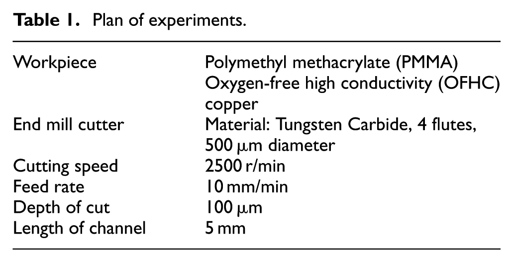
Micromilling experiments are carried out on a three-axis hybrid (micromilling and EDM) CNC machining centre (Mikrotools, Singapore). The selected process parameters are given in Table 1. A new strategy is demonstrated for micromilling of a channel in the presence of carbonyl iron particles (CIP). These CIPs are energized using a permanent magnet (NdFeB, N42 grade). CIPs are widely used for the preparation of Magnetorheological (MR) fluids. MR fluid consists of micron-size CIPs, abrasive particles, carrier liquid and additives. When the magnetic field is applied (by an electromagnet or permanent magnet), CIPs are aligned along the magnetic flux lines, and abrasive particles are gripped in between the CIPs. The relative motion between the stiffened MR fluid and workpiece results in material removal (finishing or deburring) from the workpiece. MR fluids with the addition of different types of abrasive particles are successfully used for finishing of a variety of materials such as optical glass, 30 metallic components such as knee joint implant, 31 micronozzles, 32 deburring of microgroves 33 and so on. In the present case, abrasive particles are not used along with CIPs as they may damage the microchannel due to soft workpiece material. Experiments are normally performed (without using CIPs) and using CIPs under the effect of magnetic field. The average particle size of the CIPs is 1.1 µm (HS grade, BASF) as shown in Figure 1. Magnetic field helps to keep the CIPs concentrated on the workpiece surface during machining and do not flow along with the coolant. Therefore, a small quantity of CIPs are enough for micromilling, and they do not create any problem in the coolant circulation system.
Plan of experiments.
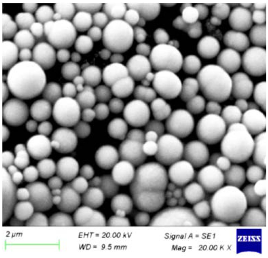
SEM image of CIPs.
Figure 2 shows a photograph and schematic diagram of the experimental setup. The workpiece (PMMA plate) is mounted over the magnet. Top surface point (Z0) of the workpiece is determined using contact probe method available on the machine for the conductive workpiece. A thin brass sheet with a known thickness is attached to the PMMA sheet and connected to the negative terminal whereas the contact probe (cutting tool) is connected to the positive terminal of the circuit. The contact point where shorting occurs between the probe and the brass sheet is taken as the first reference point, and the thickness of the brass sheet is added to get the Z0 point. CIPs and dielectric fluid as the fluid medium are supplied over the PMMA sheet. Due to a magnetic field, the CIPs are attracted together to form long chains along the magnetic flux lines, and they are concentrated near the pole of the permanent magnet as shown in Figure 2(a).
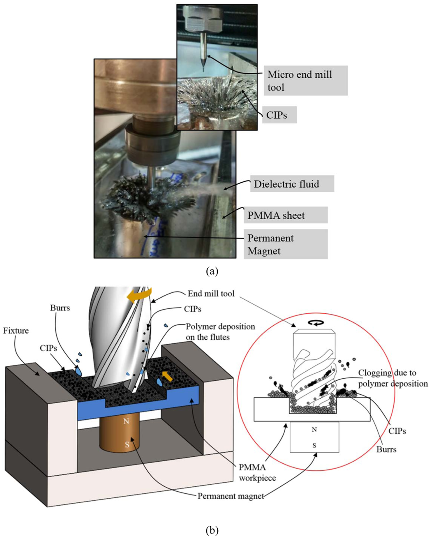
(a) Photograph and (b) schematic diagram and process mechanics of the experimental set up for simultaneous milling, deburring and tool cleaning.
After completion of the milling process, the tool is retracted from the surface, the workpiece is removed from the fixture and cleaned thoroughly. The experiment is repeated without using CIPs and keeping all other parameters constant as given in Table 1. The milling experiments are then repeated for Oxygen-free high conductivity (OFHC) copper workpiece to evaluate the performance of the proposed method in metals. Here, the Z0 point is directly measured using the contact probe as the workpiece is conductive. Same machining parameters and working fluids are used for milling microchannels.
The microchannels are examined using scanning electron microscopy (SEM) to identify the potential benefits of using CIPs during the milling process. Microscope images of end mill tool before and after machining are also captured to understand the effect of the presence of CIPs on tool surfaces. Finally, a three-dimensional (3D) optical profilometer is employed to check the surface quality of the machined channels.
Results and discussion
Figure 3 shows the comparison of SEM images of entry and exit locations of microchannel after machining in the normal way and using CIPs. It is observed from Figure 3(a1)–(a3) that microchannel machining in PMMA with normal milling operation results in burr formation on all the edges of the channel machined. Furthermore, the bottom surface of the channel is also very rough due to tool marks. Machining with concentrated CIPs using magnetic field results in no burr formation, and the bottom surface of the channel is also smooth as compared to normal milling operation as shown in Figure 3(b1)–(b3). Similarly, normal machining of OFHC copper results in burr formation (Figure 3(c1)–(c3)). While using the proposed strategy, burr formation is substantially reduced as shown in Figure 3(d1)–(d3). It is clear from Figure 3 that the proposed method of simultaneous milling and deburring of microchannel is very effective and the channel does not require any post-processing operation (deburring or finishing).
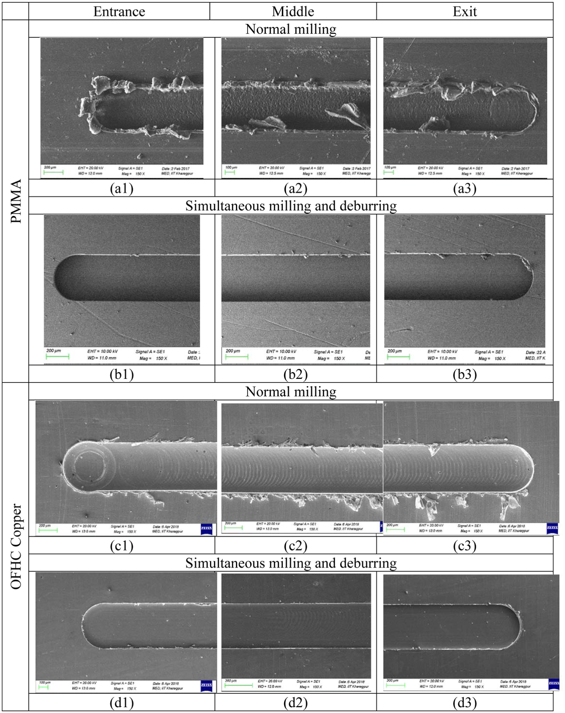
SEM images of the microchannels fabricated by normal milling process in (a1)–(a3) PMMA and (c1)–(c3) OFHC copper and by proposed machining strategy in (b1)–(b3) PMMA and (d1)–(d3) OFHC copper.
Apart from the burr formation, tool loading in polymer machining is also a very serious problem as compared to metallic material. 29 The effect of the presence of CIPs on the tool loading is also studied and compared with the normal milling operation. Figure 4(a) and (b) shows the microscope images of the end mill tool after normal milling and CIP-assisted milling operation. After normal milling operation, the flute is clogged with a solidified polymer layer which is adhered to the surface and not in an easily removable condition (Figure 4(a)). The polymer depositions will increase the chip load as the machining goes on and eventually causes the tool failure. The depositions are also visible near to the tool cutting edge which makes the tool blunt or increases the edge radius. Figure 4(b) shows that the CIP particles are successful in removing the deposition from the flutes during machining. During machining, CIP particles may follow the path of the flute and remove the depositions from time to time. This avoids the manual intermittent cleaning of the flute surface. Moreover, it reduces the total chip load and effective edge radius during machining which results in more of a cutting action than ploughing during milling.
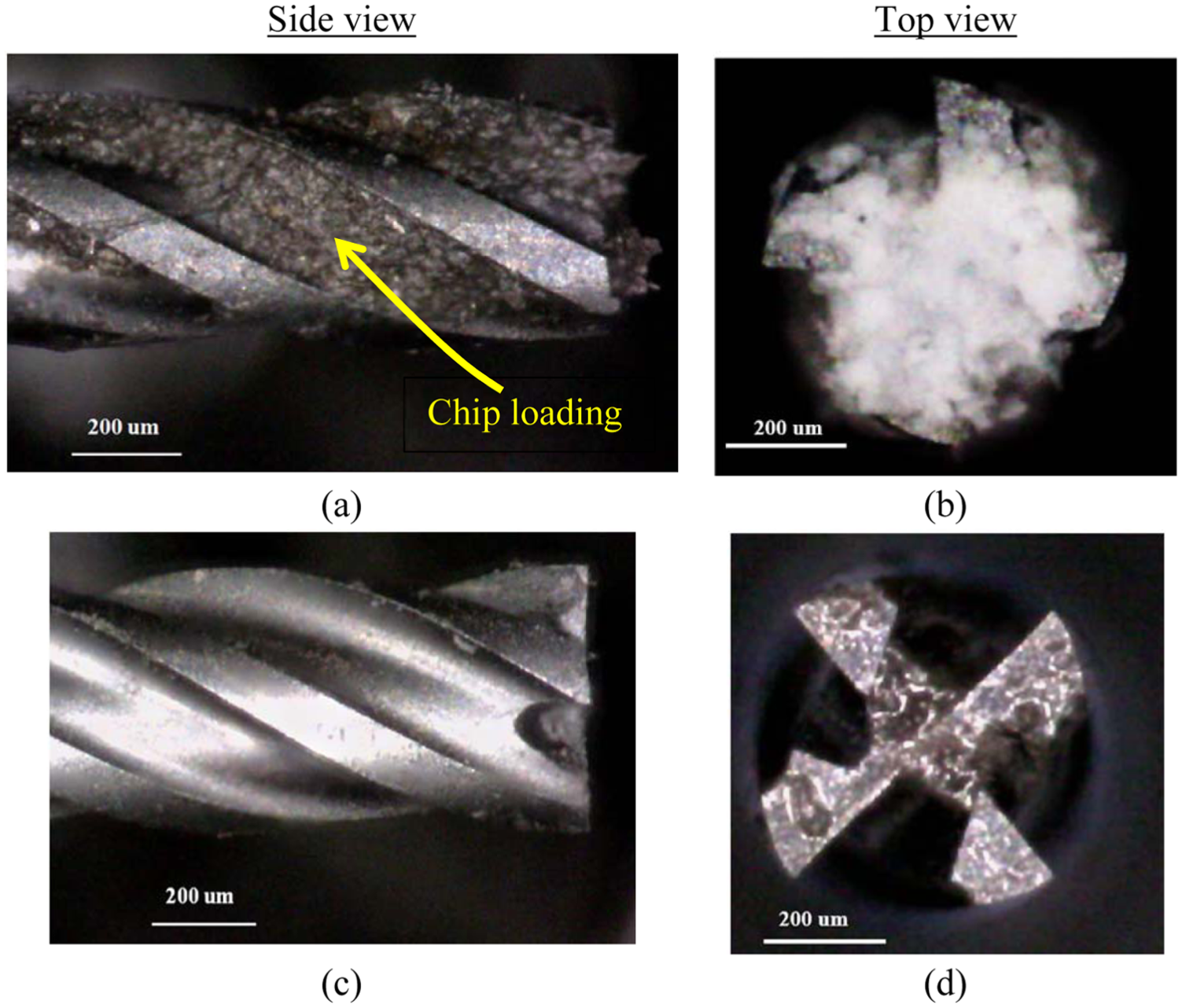
Microscope images of the tool (side and top view) after (a and b) normal milling and (c and d) machining by the proposed strategy.
The areal surface roughness of the base of the microchannel is also measured using a 3D non-contact profilometer in both cases as shown in Figure 5. Figure 5(a) reveals that the quality of the vertical wall and the bottom surface is affected by burr formation in a normal milling operation. Figure 5(b) shows noticeable improvement in the quality of the surface machined with the assistance of CIPs. The channel machined by normal milling process shows the areal surface roughness value Sa = 0.977 µm whereas the presence of CIPs has improved the surface finish of the bottom surface to a roughness value of Sa = 0.202 µm. Similarly, microchannels machined in OFHC copper using the proposed strategy also exhibit higher surface quality as the surface roughness reduces from Sa = 0.148 µm to Sa = 0.084 µm. Hence, it is concluded that using CIPs assisted milling operation; a clean machining operation is achieved by performing cutting and deburring of the microchannel as well as cleaning of the microtool simultaneously.
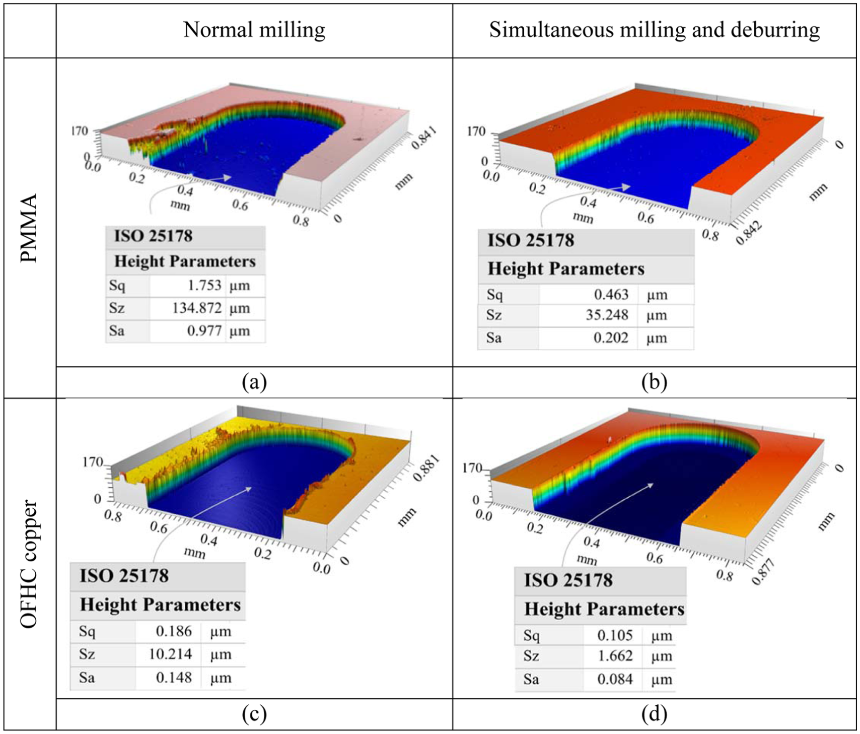
Three-dimensional profile and areal surface roughness parameters of the machined channel by normal milling on (a) PMMA and (c) OFHC copper and by proposed machining strategy on (b) PMMA and (d) OFHC copper.
The proposed method can be advantageous in machining of microfeatures at relatively low rotational speed of the tool. When using high rotational speed of the tool, spreading of CIPs may happen and they may also be embedded in the soft workpiece surface. The spreading of CIPs may be avoided by using high strength permanent magnet. It is also important to note that the flute size (depth and width) needs to be bigger than the size of CIPs for their unrestricted movement during machining and to avoid tool loading.
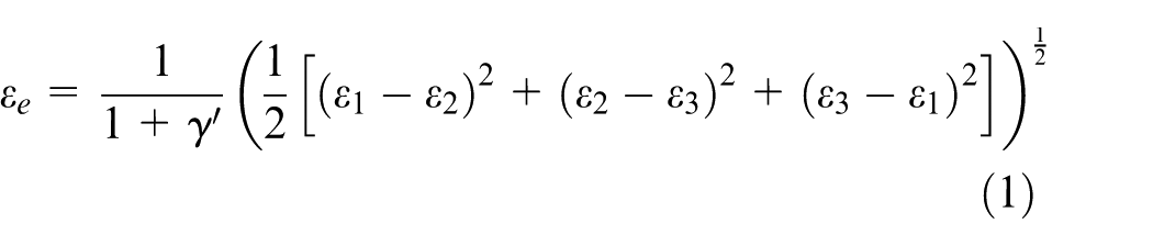
Theoretical investigation
When the rotating end mill tool is introduced into the concentrated CIPs, they also rotate along with the end mill tool. As the tool cut the microchannel, the CIPs at the end of the chains will be thrown outwards with a velocity equal to the tangential velocity at that point. The particles will move along the bottom surface, top surface and walls of the channel and will impact on the microburrs formed during machining. This impact causes bending, and plastic flows to the unwanted protrusions and the burrs will get removed. Moreover, the vortex of the fluid medium with CIPs will result in a flow of CI particles along the flute surface of the cutting tool which will remove the clogged polymer material or will avoid the chance of material deposition.
To understand the proposed method more in depth, a theoretical study is carried out to analyse the interaction of CIPs with the workpiece as well as the tool. A damage failure model has been simulated in ABAQUS® by considering PMMA as the workpiece material. The burrs are assumed to be pyramidal in shape for simplified calculations as shown in Figure 6. The CIP particles which are thrown with a velocity equal to the tangential velocity of the cutting tool will collide with the burrs. The simulation will examine the capability of CIP particles to remove burrs with the momentum gained from the rotation of the tool. Two-dimensional (2D) geometrical model of the burr is approximated to a triangular shape and modelled in ABAQUS®. The damage modelling is done similar to the impact of projectiles on to PMMA plate with low velocities.
34
PMMA with density ρ = 1190 (kg/m3) is taken as the material of burr. Elastic properties were selected as E = 5.7 (GPa) and ν = 0.42. Drucker–Prager plasticity model (friction angle β = 20°) with strain dependent hardening is applied.
35
Stress–strain curves for PMMA at different strain rates are used to introduce the characteristics of strain rate dependent hardening of the polymer. Ductile failure with damage evolution
34
is used as the failure criteria in which the plastic failure strains (
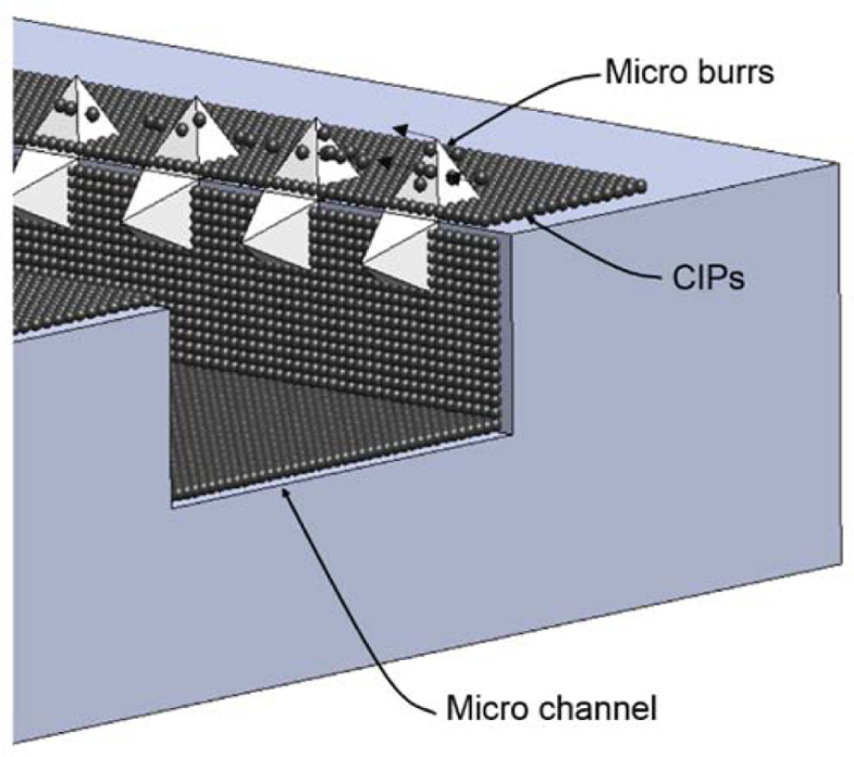
Visualization of deburring mechanism in CIP-assisted milling.
The CIP particles are configured with the properties of iron. Density is taken as ρ = 7800 (kg/m3) and elastic properties are defined with Young’s modulus E = 210 GPa and Poisson’s ratio = 0.3. A series of CIPs are arranged with all degrees of freedom and velocity equal to the tangential velocity (0.065 m/s) at the periphery of the milling tool (0.5 mm dia.) rotating at an angular speed of 2500 r/min. The contact between the particles and burr surface is defined with the surface to surface contact with penalty friction (frictional coefficient 0.3). The base of the triangular burr is defined as encastre (zero degrees of freedom) and all other surfaces attributed with all degrees of freedom. Quad dominated elements are used for meshing in which fine meshing is applied to the edges where the impact is bound to happen.
The particles are allowed to hit on the surface of the burr one after another with the defined velocity and the changes in equivalent plastic strain
Damage evolution of microburrs due to the impact of CIPs are shown in Figure 7. From this, it is clear that the CIPs are capable of removing burrs by continuous bombardment with the burr surface with the acquired velocity from tool rotation.
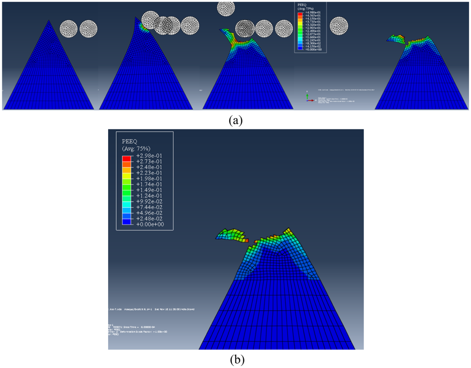
(a) Damage evolution of microburrs at different time steps and (b) plot of equivalent plastic strain of the model in the final step.
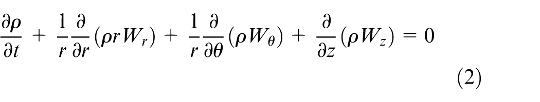
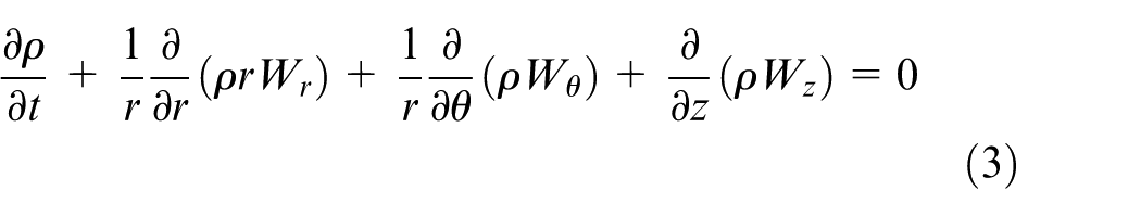
To understand cleaning of cutting tool by CIPs, the possible flow path of CIP particles during machining is simulated using the commercially available CFD package ANSYS CFX®. A steady-state simulation using k-epsilon turbulence model with scalable wall functions is performed. The direction of rotation of the tool is selected as same as in the machining process with a cutting speed of 2500 r/min. The geometry of the model along with inlet and outlet of the flow of the coolant and CIPs are shown in Figure 8(a). Ambient pressure and temperature are given as the boundary conditions for the inlet and outlet surfaces. The fluid flow rate is taken as 0.79 mm3/min corresponding to a tool feed of 10 mm/min. The model is meshed with fine tetrahedral grids and refined to finer mesh at curves and proximities. The mass and momentum equations were solved using ANSYS CFX® solver. The governing equations
36
for the conservation of continuity is given as equation (2) and conservation of momentum as equations (3)–(6) in the relative frame of reference in which
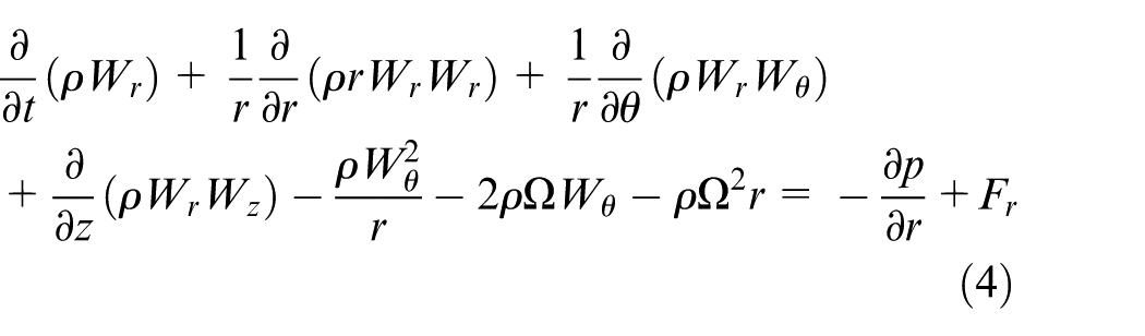
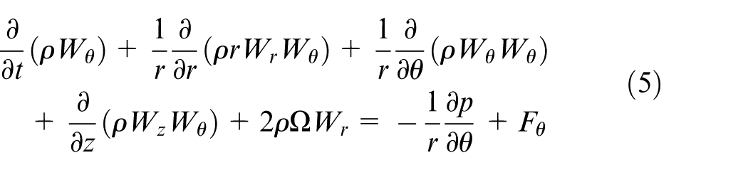
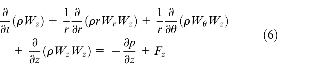
The above equations include the Coriolis and centripetal acceleration terms introduced by the relative frame of reference. For modelling turbulence characteristics of the flow, k –ε model with scalable wall functions has been used, which offers a good compromise regarding accuracy and robustness. 37 For solving these discretised equations, a high-resolution scheme for advection terms and first-order scheme for turbulent schemes are selected. The simulated flow path is visualized in Figure 8(b). It is clear from the figure that during the milling process when the tool immersed in a fluid medium with CIPs, the particles at the bottom will be thrown tangentially with a velocity equal to the cutting velocity of the tool which is responsible for the deburring operation. The loosely bonded CIPs at the end of the chains will travel along the flute as shown in the flow path diagram in Figure 8(b). A small video clip of Figure 8(b) is also added as a supplementary data which shows the movement of CIPs along the flute during the milling operation. This will be responsible for the removal of the polymer chips which are clogged in the flutes or the flow will not give enough time to the polymer chips to deposit on the flute surface and cutting edges.
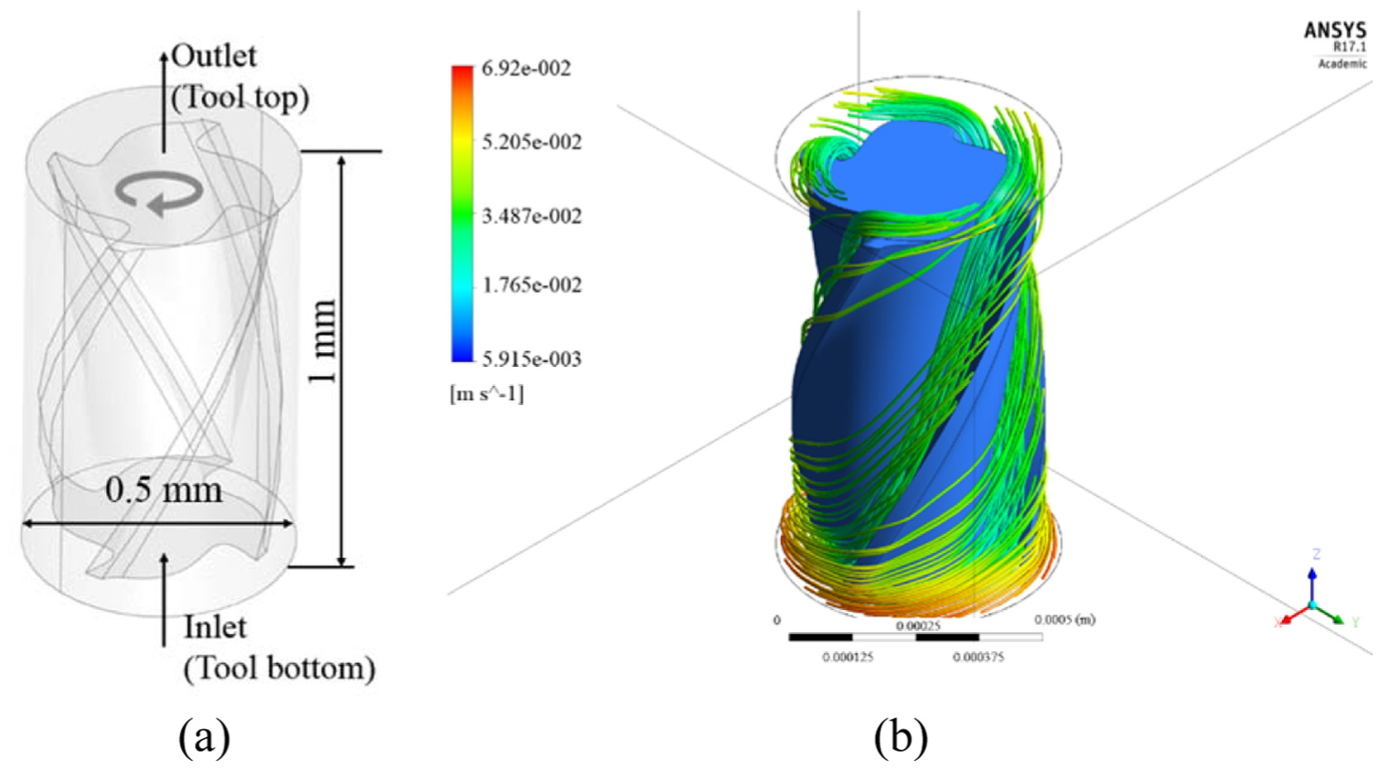
(a) Geometry of the model with boundaries and (b) visualization of the flow path using stream lines.
Conclusion
The proposed strategy realizes a new method to reduce burr formation and tool loading simultaneously in micromilling. The proposed method includes the use of micron size CIPs which are concentrated over the machining area with the help of a permanent magnet. The effect of the presence of CIPs in the machining area is investigated experimentally as well as theoretically. The following conclusions can be drawn from the present study:
Presence of CIPs during machining improved the surface quality of the channel by removing the microburrs from PMMA as well as OFHC copper.
CIPs also take part in cleaning the tool surface during machining of PMMA and avoid the polymer depositions and clogging of flutes.
Simulation of the movement of CIPs reveals that continuous striking of CIPs on burrs helps in deburring and their flow along the flutes of the cutting tool results in tool cleaning. These both happen simultaneously and avoid additional deburring or tool cleaning operation.
Areal surface roughness (Sa) of the base of the microchannel is also reduced to 0.202 µm by proposed strategy as compared to 0.977 µm by normal micromilling in case of PMMA machining. Similarly, for OFHC copper, Sa obtained is 0.084 µm by the proposed strategy and 0.148 µm by the normal micromilling.
The proposed method can be used as an economical and effective single-step process carried out at low tool RPM for fabrication of microchannels for different applications.
It is necessary that the flute size (width and depth) is bigger than the size of CIPs. Otherwise, CIPs movement may be restricted in the flute and the proposed method may not be effective.
Footnotes
Declaration of conflicting interests
The author(s) declared no potential conflicts of interest with respect to the research, authorship and/or publication of this article.
Funding
The author(s) disclosed receipt of the following financial support for the research, authorship, and/or publication of this article: The authors acknowledge the funding support from the Institute under SGDRI grant and Science and Engineering Research Board (SERB) under young scientist scheme (YSS/2015/001163).
References
Supplementary Material
Please find the following supplemental material available below.
For Open Access articles published under a Creative Commons License, all supplemental material carries the same license as the article it is associated with.
For non-Open Access articles published, all supplemental material carries a non-exclusive license, and permission requests for re-use of supplemental material or any part of supplemental material shall be sent directly to the copyright owner as specified in the copyright notice associated with the article.