
Abstract
The present study is numerically investigated the effects of successively various location and tilted angle of piezoelectric fan on the heat transfer performance of a uniform heated cylindrical surface by piezoelectric fan. Since the blade vibrates periodically, three dimensional laminar, pseudo-steady-state natural convection flow is assumed. The discrete structure of fluid domain adopts the dynamic meshing scheme to simulate the three-dimensional time-varying geometries of the vibrating blade. Thus, numerical analysis can define precisely the motion of piezoelectric fan along the length of the blade at each time step. The numerical results infer that the heat transfer augmentation by piezoelectric fan is mainly contributed with two factors: One is the scale of produced vortex region by the vibrated blade; the other is the direction of induced jet-like stream impinging to the heat transfer surface. To obtain the optimal heat transfer augmentation, a total of 12 piezoelectric fans with various blade orientations from the bottom section of the cylinder to the flat top surface are evaluated. The cases of P4 (y/H = 0.625) and P2 (y/H = 0.375) provide the best heat transfer augmentation ratios 1.92 and 1.41 for the fan tip dimensionless amplitude equal to 2 and 1, respectively. However, the worst heat transfer performances occur at the positions P12 and P11 for dimensionless amplitude equal to 2 and 1.
Introduction
Natural convection is a common heat transfer mechanism for electric equipment cooling. However, its relative poor heat transfer performance induces local hot spots problem. Thus, heat transfer enhancement techniques are required to prevent overheating and possible component damage. Piezoelectric fan has been considered as an effective cooling device for poor heat transfer coefficient condition, owing to its advantages of less space occupied, low noise, and low power consumption. Piezoelectric fan is composed of a thin flexible blade affixed to a piezoelectric patch. It is actuated at the resonant frequency of piezoelectric ceramic by an alternating voltage. The blade vibrates at the resonate frequency to achieve maximum deflection of the blade; and creates a jet-like flow from the fan base toward the fan tip. The flow is changed from natural convection into forced convection, and results in a significant heat transfer enhancement. 1
Toda2,3 pioneered the research on piezoelectric fans and observed the flow field developments induced by a vibrating PVF2 bimorph fan. The results indicated that the induced air flow rate was proportional to the blade width and thickness. From the literature review, until now, many of the literature utilized experiment to observe the flow and temperature field developments near heated surfaces for various piezoelectric fans arrangements.4–7 These results revealed that the flow and thermal characteristics is dependent predominantly on the fan length, the clearance between the fan tip and the heated surface, the vibration amplitude of the fan tip, and the actuated fan resonant frequency. Liu et al. 8 investigated experimentally the heat transfer of a piezoelectric fan positioned horizontally or vertically above a heated plate. It showed the heat transfer augmentation ratio has a symmetrical distribution with a peak at x/L = 0.5 for horizontal case, but an asymmetrical distribution with a peak at x/L = 0.25 when the fan was placed vertically. As for the numerical literature, a simplified 2-D model geometry is usually adopted to numerically simulate the flow field characteristics and heat transfer phenomena around piezoelectric fans.9–13 They indicate that suitable arrangement of piezoelectric fans can significantly enforce the flow and suppress the thermal boundary layer of the heated surface and up to a 52% increase in the local heat transfer coefficient is obtained in the natural convection flow. 10
In the last decade, Lin14,15 executed 3-D numerical analyses and studied the heat transfer enhancement by use of piezoelectric fan for the natural convection flows along flat-plated and cylindrical heat sources. The results described the detailed 3-D velocity structures and streamlines around the piezoelectric fan and heated surfaces. They demonstrated that the piezoelectric fan improved the average heat transfer coefficient by 1.6–3.6 times for the flat-plated heat source and 1.2–2.4 times for the cylindrical heat source. Sufian et al. 16 considered two synchronized piezoelectric fans positioned around a heated plate, and showed that the fans enhanced the heat transfer performance by almost three times compared to the natural convection flow. Lin 17 performed a 3-D forced convection channel flow and investigated the velocity field and heat transfer enhancement of a heated cylinder by a vibrating piezoelectric fan placed in the wake region. Abdullah et al. 18 and Li et al. 19 were interested in the effects of the piezoelectric fan configuration and location on the cooling system composed of piezoelectric fan and finned heat sink. Li et al. 6 studied numerically the flow and heat transfer performance induced by multi-vibrating piezoelectric fans for cooling heated semi-cylindrical concave surface. Kim and Yeom 20 evaluated the channel-flow convection heat transfer enhancement with piezoelectric fans under three locations, denoted as the upstream, front-end, and center locations. Bilaskar et al. 21 applied two piezoelectric devices, the piezoelectric fan (PF) and the piezoelectric translational agitator (PTA), in a channel flow with a finned heat sink. Both numerical analysis and experiment were executed to investigate the heat transfer characteristics. The results indicated the finned heat sink system with both the PF and PTA enhanced the heat transfer coefficient by 76.88% compared to the system with PTA, and by 30.92% as compared to the system with the PF only. Turkyilmazoglu and Alotaibi 22 studied mathematically the classical blade coating problem, and successively derived a series of explicit formulas for practical applications. These formulas enable the calculation of key engineering quantities, including pressure gradient, load, film thickness, drag, and Nusselt numbers on both the substrate and the blade. In view of the reviewed literature, owing to rather complex flow structure, a complete 3-D numerical analysis is essential to describe such a problem of heat transfer enhancement by piezoelectric fan.
The cylindrical type heat source has many industrial applications, such as electronic devices (e.g., capacitance, inductance, and solenoid). It is crucial to manage the electronic thermal management to sustain the electronic device for good working. However, the suitable suggestions concerning the geometries and arrangements of piezoelectric fan applied on a heated cylinder are attracted less attention. Lin15,17 focused on the free/forced convection channel flows of the heated cylinder and provided in detail the induced velocity fields and heat transfer performances of horizontally vibrating piezoelectric fan. However the influences of geometric parameters, including the piezoelectric fan horizontal/vertical arrangement, the piezoelectric fan relative location with the cylinder, blade tip amplitude, and clearance between the tip and cylinder, on the flow and heat transfer performance haven’t yet been studied. With respect to the above topic, Lin and Leu 23 studied the effects of piezoelectric fan horizontal/vertical arrangement, the piezoelectric fan relative location with the cylinder, clearance between the tip and cylinder on the heat transfer performance of heated cylinder. The cylindrical heated sources include constant heat flux boundary conditions acting on both the cylindrical surface and the upper (flat) surface. Recently, Razak et al. 24 considered the orientation of the blades and developed a radial piezoelectric magnetic fans (RPMF) mathematical model to manage the electronic thermal management. Compared to traditional array piezoelectric magnetic fans (APMF), RPMF is 5% more efficient than APMF in cooling the heat source because the RPMF able to generate higher resource frequency and slightly wider deflection than the APMF. The reason of RPMF with higher resource frequency is due to additional centrifugal force produced by the radial orientation arrangement. The objective of the present study is to extend the above researches for searching the optimum geometric arrangement of piezoelectric fan. A total of twelve different orientations which varies successively the piezoelectric fan location and tilted angle are proposed. The influence of various piezoelectric fan location and tilted angle on the heat transfer rate has not been evaluated yet. The three-dimensional numerical study is going to simulate the flow and temperature characteristics. The optimal location of piezoelectric fan is then evaluated through calculating the heat transfer augmentation ratio of these 12 proposed cases for different blade tip amplitude.
Theoretical analysis
The work mainly studies the influences of piezoelectric fan location and attitude on the heat transfer enhancement of natural convection flow around the cylinder. The physical model and geometry is shown in Figure 1, where x-axis and y-axis are the aligned direction of piezoelectric fan and cylinder axis, respectively. The vibration direction of piezoelectric fan is set to the y-direction. The geometric parameters of physical modes are summarized in Table 1 and described as follows: The overall dimensions of the cylinder are the diameter D and length H (6.35 mm × 50.8 mm). w is the width of the blade (12.7 mm), the length of blade is 76.2 mm. d is the clearance distance between the tip of the fan and the cylindrical surface (6.35 mm). The computational domain had dimensions of (76.2 + d + 3D) mm × 101.6 mm × 127 mm. To evaluate the maximum heat transfer augmentation, the positions of the piezoelectric fan are arranged at 12 different positions, as shown Figure 2. Position P1 is located at y/H =0.25, an increase by y/H = 0.125 is added along the positive y-direction named P1–P7. And P7 is just located at the same plane of the cylindrical top flat surface, that is, y/H = 1.0. In addition, the piezoelectric fan is rotated every 22.5 degree until the piezoelectric fan is aligned the tangent direction of the circumference surface (P11); finally the piezoelectric fan is installed along the axis of heated cylinder (P12). Noting that, the clearance d is remained at 6.35 mm for all the cases. Two different fan tip amplitude of 25.4 and 12.7 mm (denoted as α = 2 and α = 1) are considered for all the cases.
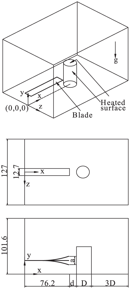
The schematic diagrams of physical model and corresponding top view and side view.
The corresponding geometry of the physical model for calculation.


The dimensions and arrangements of piezoelectric fan and heated cylinder.
For the present study, the fluid is considered incompressible with constant properties except the density. The density of the air surrounding the piezoelectric fan and cylinder is considered as a temperature-related third order polynomial function. The other thermal properties (e.g., viscosity and thermal conductivity) are treated as constants determined in accordance with the film temperature of the air surrounding and the heated surface, that is,

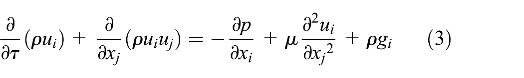
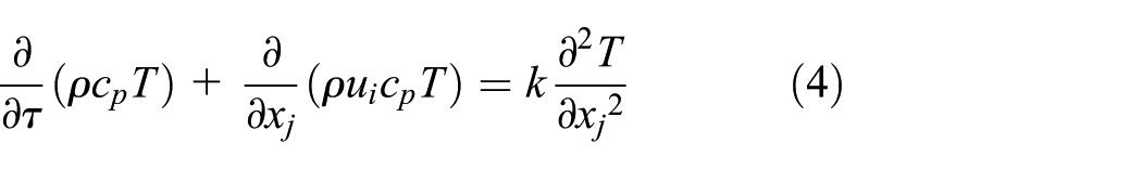
Since the blade vibrates periodically, both the flow and temperature fields vary over time. The flow is assumed to be laminar, transient, and no viscous dissipation and radiation heat transfer effects. The continuity, momentum and energy equations for natural convection flow may be expressed in tensor form as:

Note that, the ambient air temperature T∞ is taken to be 300 K. The heated cylindrical surfaces are set as boundary conditions. And a uniform heat flux of q = 500 W/m2 is applied on both the sidewall and top surface of the cylinder.
In the present study, the blade is modeled as a thin slender beam. Thus, the displacement of each point along the piezoelectric fan is described by the following polynomials 25 :


The constants used in the equations (5) and (6) have the following values:

The instant displacement is expressed as sin (2πfτ). Thus, the instant velocity of piezoelectric fan in vibrating direction is calculated as

where
The heat transfer coefficient h is defined as the heat flux on the heated surface


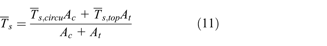
where A
c
and A
t
are the circumferential surface area and top surface area of the heated cylinder, respectively; and
Numerical method
A commercial code ANSYS FLUENT (2018) was used to execute the numerical analysis of 3-D steady natural convection flow. The SIMPLE algorithm was adopted in calculating the pressure field of the momentum equations, in which the convective terms were treated using the upwind scheme. The vibration period (T = 0.032 s) was partitioned evenly into 80 time steps, Thus, the transient numerical simulations give a temporal resolution per 0.0004 s. The location and displacement of each point along the length of the blade was calculated precisely at each time step utilizing a user-defined function (UDF) incorporated in ANSYS FLUENT. The grid system is schematic in Figure 3. The 3-D grid system is complex. For ease of description, the mesh model only shows at the neutral plane of the cylinder (i.e., z i.0). To increase the accuracy and convergence speed of the numerical scheme, the mesh was densified at the regions near the piezoelectric fan and cylinder. The base grid interval size was about 2.0 mm, and a fine grid size (0.25–0.5 mm) was located around the regions of the piezoelectric fan and cylinder to ensure the satisfaction of numerical stability. To obtain the solutions in this simulation, the average surface temperature of the heating cylinder over every vibrating period are calculated. The convergence criteria of pseudo-steady state solutions are determined while the relative errors

The grid system of the simulation model.
Results and discussions
Figure 4(a)–(e) shows the streamlines released from the blade edges of the vibrating fan when it moved to the neutral position in both the upward and downward directions, where the amplitude of the fan tip is α = 2, and the clearance between the fan tip and the cylinder d = 6.35 mm. The displayed fan locations are the positions of P2 (y/H = 0.375), P4 (y/H = 0.625), P7 (y/H = 1), P9 (y/H = 1.088, 45° tilted) and P11 (y/H = 1.125, vertical), respectively. As presented in the previous literature,12,14,18 the heat transfer enhancement of the piezofan is contributed by two streams: the first is the jet-like flow in front of the fan tip and the other is the induced air streams during each vibrating cycle. The induced air streams turn into two counter-rotating vortices, starting from the base of piezofan toward the tip of blade, as a result of combination of jet-like flow produced by the piezofan and the dragged force of the vibrating blade. This phenomenon is seen in Figure 4. The screwed type flow injects to the heated cylinder, and carries heat away from the heated surfaces. In the meanwhile, the flow streams also suppress the growth of thermal boundary layer, resulting in increases of the temperature gradient and heat transfer enhancement.
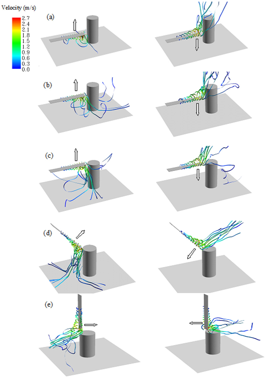
Flow streamlines released from the piezoelectric fan in both the upward and downward directions at five specific positions (α = 2); (a) P2, (b) P4, (c) P7, (d) P9, and (e) P11.
An inspection of Figure 4 (a)–(e) also shows the flow structures and mutual differences of computational domains for specific positions ((a) P2, (b) P4, (c) P7, (d) P9, and (e) P11). In principle, while the piezofan moved in upward (or rightward) process (the left column of Figure 4), the induced streams by the vibrating blade are mostly affected by the bottom solid wall. This influence is more significant as closer distance between the piezofan and bottom wall (such as Figure 4(a)). As the piezofan installs gradually away from the bottom wall (Figure 4(b) and (c)), a greater amount of air is entrained by the moving blade and the jet-like flow streams cover a wider range of the heated cylindrical circumference surface. While the piezofan installs above the top flat surface (Figure 4(d) and (e)), messes of streams are incident on the circumference surface. After the piezofan arrives at the maximum displacement, it moves in the downward (or leftward) process and back to the neutral position. The corresponding flow streamlines released from the blade edges are showed in the right side of Figure 4. Because the space behind the moving piezofan is unconstrained, the streams are entrained by the vibrating blade and flows over the cylindrical surfaces. For the cases of piezofan locations beneath the top flat surface (P2, P4, and P7), the induced streams flow along the cylindrical circumference surface. However relative less streams flow over the top flat surface due to its location perpendicular to the circumference surface. The cases of P9 and P11 display the opposite phenomenon. The induced streams entirely flow over the top flat surface; however they cannot keep flowing along the cylindrical circumference surface. In conclusion, during a whole vibrating period, the piezofan installed beside the circumference surface can blow more effectively the streams over the entirely heated surfaces and achieve greater heat transfer performance.
Figure 5 schematically explains the above conclusion by velocity contours. Figure 5(a)–(e) shows the corresponding velocity contours of computational domains for different fan positions specified in Figure 4. The velocity contours indicate the flow structure and strength in the computation domain. In the Figure 5(a)–(e), a significant large-scale vortex is induced in the back region of piezofan while the piezofan vibrates upward and downward, where possesses a maximum velocity of 2.4–2.7 m/s. Depending on the piezofan vibrating direction, the vortex is formed in the solid-constrained or unconstrained regions. The induced vortex injects to the circumference and top surfaces of heated cylinder and takes heat away. The intensity of flow velocity gradient near the cylinder dominates the heat transfer performance. The larger velocity gradient is, the better heat transfer performance is. In addition, the covered area of vortex is another factor to affect the heat transfer performance. The heat transfer area of the present model includes the circumferential and top surfaces of cylinder. The broader region vortex covers, the better heat transfer performance is. Among Figure 5(a)–(e), (P4, y/H = 0.625) possesses simultaneously the stronger velocity gradient and broader covered area of vortex while the piezofan vibrates upward and downward. It is expected to produce the better heat transfer performance than the other piezofan positions. It is noted that, although the cases P7, P9, P11 produce larger scale vortices to inject the top plate of cylinder, the velocity gradient near the circumferential surface is decreased instead. So the entire heat transfer performances for the cases P7, P9, P11 are expected less than the case P4.

Velocity contours around the piezoelectric fan in both the upward and downward directions at five specific fan positions (α = 2); (a) P2, (b) P4, (c) P7, (d) P9, and (e) P11.
Figure 6(a) and (b) displays the dimensionless temperature θ of the heated cylinder under actuation of piezofan for fan tip displacement amplitude of α = 2.0 and 1.0, respectively. The white symbols (diamond, circle, and up-pointing triangle) at the curves mean the results simulated in the reference Lin and Leu. 21 The related black symbols are the present studied cases. For Figure 6(a)α = 2.0, the temperature of circumference surface is initially decreased as increase of the installed position y/H. The minimum temperature appears at the positions of P4 (y/H = 0.625). Hereafter, the temperature increases steeply as the installed position above the top flat surface (y/H ≥ 1.0, P7–P10), and at last, the zone from P11 to P12 occurs a significant temperature jump. Noting that the temperature of P12 is almost equal to 1, it infers that no extra heat is taken away by the piezofan while it is installed along the axis of the heated cylinder. Take a close look in Figure 6(a), the temperatures profile of the top flat surface continuously decreases as the location of piezofan varies from the bottom of cylinder toward the top flat plane of the cylinder. While the piezofan location is above the top flat plane, the temperature profile is decreased dramatically. Comparing the temperature of circumference surface as stated above, the temperatures of the top flat surface are almost the same for positions of P11 and P12. Thus, if the heat removal is important demand for the top flat surface, the positions P11 and P12 are suitable locations. The trend of weighted average temperature of entire heated surfaces is similar to the temperature of the circumference surface as a result of greater area weighted on circumference surface (see equation (11)). The cylinder temperature for the amplitude of fan α = 1.0 is displayed in Figure 6(b). Compared with Figure 6(a), the trend of α = 1 is similar to the case of α = 2. However, because the vibrating amplitude is smaller, the induced flow streams cover a narrower range of heated surface. Then, relative higher temperature profiles and worse heat transfer performance are achieved. Similarly, the trend of weighted average temperature of entire heated surface is similar to the temperature of the circumference surface. The minimum temperature of heated circumference surface appears at P2 (y/H = 0.375). Then the temperature increases as the installed height of the piezofan increases. While the installed position is P11 or P12, the temperature is almost equal to 1. As for the temperature of the top flat surface, it is almost kept at the same value for the installed position from P1 through P5. Because the displacement of the fan tips are always beneath the top flat surface, and the jet-like flow cannot reach the top flat surface. Unlike the temperature shown in Figure 6(a) for P11 and P12, the temperature of the top flat plane is lower for position P12 than that of P11. The reason is the displacement of fan tip for α = 1.0 is just half of the cylindrical diameter, the flow covered range of the top flat plane is not as wide as that of α = 2.0, as a result while the piezofan installed along the axis of the heated cylinder has a better flow covered range on the top flat surface.

Variation of dimensionless temperature as function of different piezoelectric fan positions: (a) α = 2 and (b) α = 1.
The variations of heat transfer augmentation ratio ξ versus piezofan position (y/H) for α = 1 and α = 2 are shown in the Figure 7. The heat transfer augmentation ratio ξ is defined as
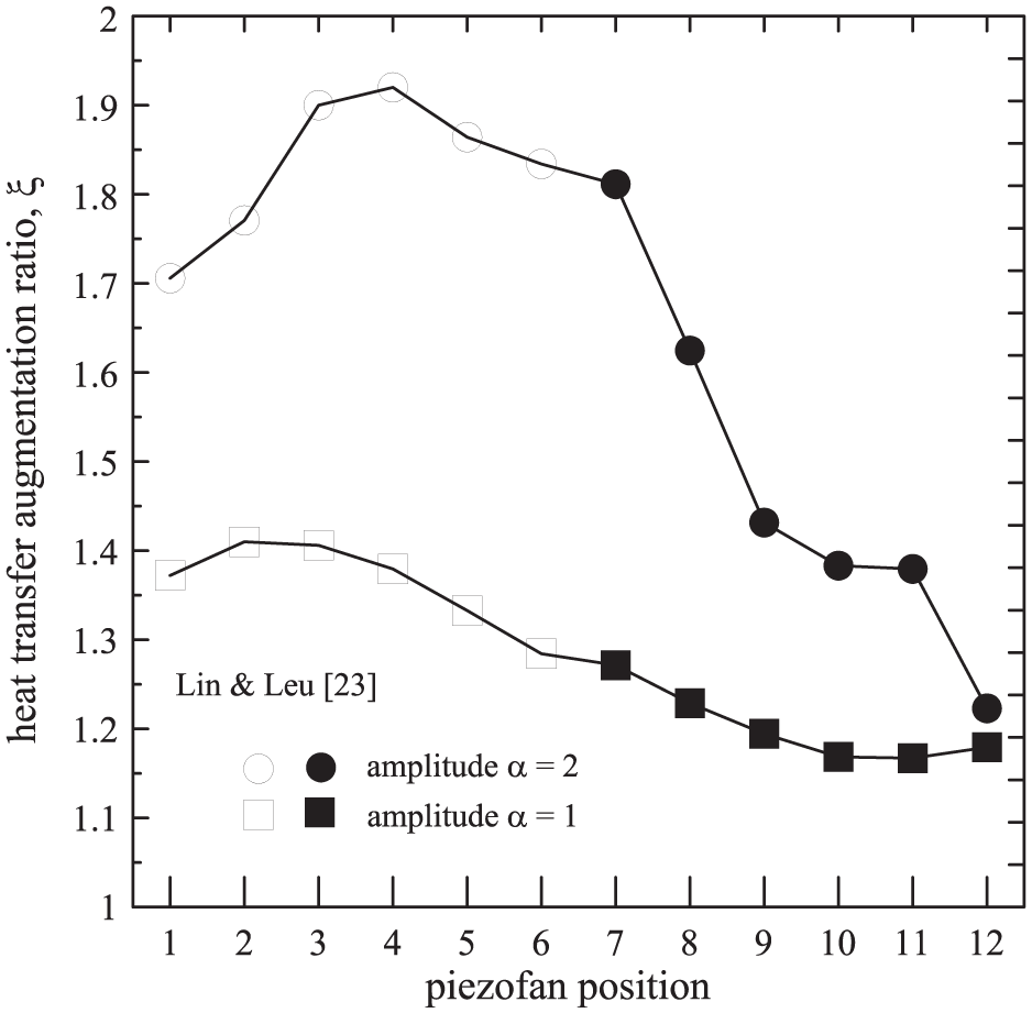
Variation of heat transfer augmentation ratio as function of different piezoelectric fan positions.
Conclusions
This study performed a numerical investigation into the 3-D flow and heat transfer performance around a heated cylinder cooled by a vibrated piezoelectric fan arranged with twelve various locations. Besides the 3-D streamlines and velocity contours are illustrated clearly, the variations of average temperature and heat transfer augmentation ratio with the twelve proposed locations for two different fan tip amplitude are also depicted. The following major conclusions are achieved:
During the vibrating process, the piezoelectric fan induces a pair of screw-type streams, starting from the base of piezoelectric fan toward the tip of blade. In addition, the piezoelectric fan tip produces a jet-like stream. The two streams inject to the heated cylinder and carry heat away from the surface, and then enhance the heat transfer performance.
While the piezoelectric fan moves in upward process, the induced streams by the vibrating blade are mostly limited by the bottom solid wall. The influence is more significant for the closer distance of the piezoelectric fan and the bottom wall. For the piezofan positions P7–P12, the induced streams produce larger vortex regions behind the moving blades than those of piezofan positions P1–P6.
The flow velocity gradient near the surfaces is the dominant factor to affect the heat transfer performance. The heat transfer performance of piezoelectric fan plays an effective role only when its jet-like stream impinges perpendicularly on the heat transfer surface.
The average temperature profile of cylinder surfaces for the case of dimensionless amplitude equal to 2 is lower than that of dimensionless amplitude equal to 1. In addition, the minimum of cylinder surface temperatures appear at the positions P4 (y/H = 0.625) and P2 (y/H = 0.375) for the cases of dimensionless amplitude equal to 2 and 1, respectively. Oppositely, the maximum temperatures appear at the positions P12 and P11 for the cases of dimensionless amplitude equal to 2 and 1.
Follow the above conclusion, through the evaluations of twelve orientation arrangements of piezoelectric fan, the correlated heat transfer augmentation ratios are achieved in the range of 1.24–1.92 for the case of dimensionless amplitude equal to 2 and 1.15–1.41 for the case of dimensionless amplitude equal to 1.
Footnotes
Appendix
Handling Editor: Chenhui Liang
Funding
The authors received no financial support for the research, authorship, and/or publication of this article.
Declaration of conflicting interests
The authors declared no potential conflicts of interest with respect to the research, authorship, and/or publication of this article.