
Abstract
In this paper, the numerical simulation was used to study the flow and heat transfer characteristics for twisted oval and two-start twisted helically wound tubes with Reynolds numbers 4000–16,000. The significant factors that affect the flow and heat transfer characteristics were analyzed. The range of twist pitch p is 0.02–0.10 m, and ellipse ratio r is 1.2–2 for twisted oval tube, the groove depth e is 0.4–2 mm for two-start twisted tube. The result showed that the relative friction coefficient and Nusselt number increased with the increase of ellipse ratio r and decreased with the increase of twist pitch p for twisted oval helically wound tube. With the growth of Reynolds number, the effects of twist pitch p and ellipse ratio r on the flow characteristics decreased. In addition, the average level of the thermal enhancement factor TEF of the two-start twisted was higher than that of the twisted oval helically wound tube. The maximum enhancements factor TEF of 1.1312 is obtained with groove depth of 2.0, twisted pitch of 0.02, and Reynolds number of 4000 for the two-start twisted tube. Finally, new empirical formulas for flow and heat transfer in helically wound tubes were proposed for two kinds of enhanced tubes.
Keywords
Introduction
Enhanced heat transfer technology can improve the efficiency of heat exchangers, making the equipment more compact and energy-efficient. 1 Generally, there are three forms of enhanced heat transfer technology, namely active heat transfer, passive heat transfer and composite heat transfer. 2 Passive heat transfer technology is widely used because it does not need additional energy input, 3 which can change the flow characteristics and increase heat transfer efficiency. Tubes made with rough surface technology are often known as enhanced tubes. The convex surface in the tube can produce secondary flow and disturb the fluid boundary layer, which increases the heat transfer area and improve heat transfer coefficient. These factors improve the heat transfer performance.
Compared with the circular tube, the elliptical twisted straight tube has deformation on the wall, which changes of flow characteristics. However, considering the difference in flow and heat transfer characteristics between straight tubes and helically wound tubes, it is necessary to carry out relevant research to determine the range of structural parameters suitable for the helically wound tubes. Sheikholeslami et al. 2 reviewed the passive heat transfer enhancement methods, and they found the wire coil made a better heat transfer coefficient and less friction loss. Garcia et al. 4 studied thermal–hydraulic behavior for three kinds of enhanced structure: corrugated tubes, dimpled tubes, and wire coils tubes. The heat transfer and pressure drop characteristics under several regimes were investigated. They found corrugated and dimpled tubes had a lower pressure drop. Cioncolini and Santini 5 conducted experimental research on 12 spiral wound tubes with different relative coil radius, and classified them into mild, moderate, and severe according to the size of the coil radius. The results showed that the transition from laminar flow to turbulent flow was advanced with the change of coil radius. Promthaisong et al. 6 used numerical simulation to study the flow and heat transfer characteristics of the spirally corrugated tubes. They found that the heat transfer coefficient increased with the increase of groove depth in the fully developed heat transfer section, and the best thermal enhancement factor of 1.16 was obtained when the pitch was 0.25 at the Reynolds number of 5000. Kareem et al. 7 studied the two-start spirally corrugated tube with water as a working fluid at a low Reynolds number. Five kinds of two-start spirally corrugated tubes were selected for experiment and numerical simulation. The results showed that the heat transfer coefficient increased by 21%–60% compared with the smooth tube, and the friction coefficient increased by 20%–36% compared with the smooth tube. After that, Kareem et al. 8 studied the three-start spirally corrugated tube with water as a working fluid at a low Reynolds number. The results showed that the heat transfer coefficient was 2.4–3.7 times of the heat transfer coefficient for smooth tube, and the friction coefficient was 1.7–2.4 times for smooth tube. Jin et al. 9 carried out a numerical study on six-start helical twisted tubes with different pitches and groove depth at several Reynolds numbers. The results showed that the heat transfer coefficient decreased with the increase of pitch. With the increase of groove depth, the velocity of secondary flow and the vorticity of longitudinal vortex increased gradually. The heat transfer performance of the corrugated tube increased by 1.05–1.33 times compared with the smooth tube. Cheng et al. 10 carried out experimental research on the smooth tubes and twisted oval tube at low Reynolds number (Re = 50–2000). The results showed that the effect of secondary flow for twisted oval tubes enhanced the convective heat transfer, and the enhancement factor increased with the increase of ellipse ratio, while it decreased with the increase of pitch. The best enhancement factor for the twisted oval tubes is 1.7 with the flattening of 2.0 and the twisted pitch of 0.33. Eiamsa-ard et al. 11 carried out a numerical simulation on the heat transfer enhancement of triple-channel twisted tape insert. The results showed that the heat transfer effect improved within the acceptable pressure drop range, and the arrangement of wave crest versus wave trough has a certain influence on heat transfer. And the ratio of the width of the twisted tape to the hydraulic diameter of 0.34 possessed the best thermal performance factor. Tan et al. 12 investigated the convective heat transfer and fluid flow in twisted oval tubes. The results showed that the twisted structure in an oval tube could lead to secondary flow, and the heat transfer coefficient and friction factor both increased with the axis ratio increased, while decreased with the twist pitch length increased. Tang et al. 13 investigated the heat transfer and pressure drop performances of the twisted tri-lobed tubes and twisted oval tubes. Both of them increased with the reduction of twisted pitch length. The twisted tri-lobed tube has a good performance, with the Nusselt number increased by 5.4% and friction factor increased by 8.4%, which is more suitable for heat exchange equipment. Bhadouriya et al. 14 experimentally studied the heat transfer and friction factor for twisted square ducts. They found that twisted square duct made a better performance for laminar flow regime, the heat transfer performance of 10.5 is obtained with the twist ratio of 2.5, and Reynolds number of 3000. Zhang et al. 15 conducted an experimental investigation to study the heat transfer performance of steam condensation on the twisted elliptical tube. They found the condensation heat transfer coefficient increased with the tube elliptic ties increased. Yu et al. 16 studied the thermal-hydraulic characteristic of the twisted oval tubes. The results showed that twisted tube with wire coil could enhance heat transfer rate, while the performance evaluation criteria decreased. The increase ratio of Nu and friction factor is 45.92% and 674.86%, respectively. Yang et al. 17 conducted an experimental study on heat transfer and flow resistance characteristics in the twisted elliptical tubes. They found that heat transfer performance could increase by improving the aspect ratios or reducing the twist pitches. Luo and Song 18 proposed a novel twisted annulus tube, and presented the thermohydraulic performance with a different aspect and twist ratios. The Nu and friction factor of twisted annuli are 157% and 118% compared with the straight annulus. Wang et al. 19 conducted experimental and simulation research on the helically coiled-twisted trilobal tube. The performance evaluation criteria and filed synergy number were used to evaluate the performance. And the increase of Nu of the enhanced tube is 19%–31%, while the flow resistance is 24%–38%.Wu et al. 20 investigated the turbulent convection in a twisted elliptical tubes. They found that the rotational motions produced could enhance the heat transfer. Wu and Zhou 21 studied the flow and heat transfer characteristics in corrugated tubes, and found the enhancement of heat transfer only occurred at high Reynolds numbers. Andrade et al. 22 studied the characteristics of heat transfer and pressure drop of internal flow in a corrugated tubes for different flow regimes. They found that the corrugated tube took a smoother transition, and it is more effective under the transitional flow regime. Han et al. 23 conducted a multi-objective optimal design for corrugated tubes, and they used the response surface analyzed to visualize the effects of the interactive terms. The results indicated that the heat transfer performance improvement might lead to the resistance increase. Rabienataj Darzi et al. 24 investigated the effect of helical corrugation on heat transfer and friction factor. They found that the heat transfer and friction factor increased with the corrugation height increased and the corrugation pitch decreased.
The investigation found few researches on the enhanced heat transfer technology in the LNG wound tube heat exchanger. Therefore, it is necessary to study the improved heat transfer technology of the helically wound tube and put forward the enhanced heat transfer technology suitable for the helically wound tube. In this paper, the influence of saliency factor on the flow and heat transfer characteristics for twisted oval and the two-start twisted helically wound tube was studied by numerical method. Finally, the new empirical formula for flow and heat transfer in helically wound tubes was proposed.
Numerical method and experimental verification
Numerical model
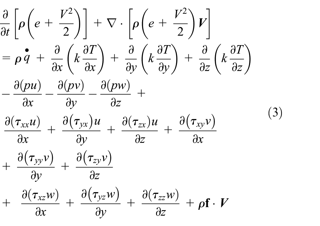
Continuity equation, momentum equation, energy equation can be expressed as follows:


In this paper, the RANS model is used as turbulence model:

Where
Computational methods and experimental verification
The oval tube and two-start twist are widely studied in the heat transfer enhancement of straight tubes. In this paper, they are applied to the helically wound tubes to construct twisted oval helically wound tube and two-start twist helically wound tube. The geometric model used in this project is obtained by simplifying the geometric model (Figures 1 and 2).
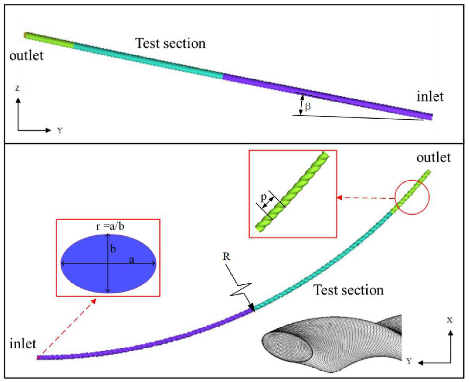
Schematic diagram of twisted oval helically wound tube model.
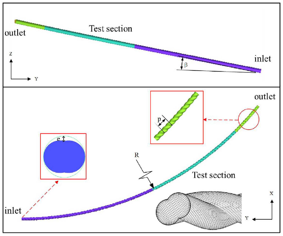
Schematic diagram of two-start twisted helically wound tube model.
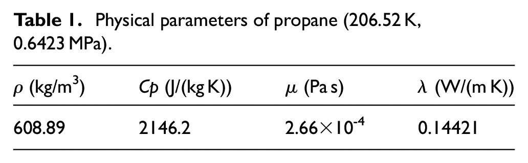
In this paper, the range of coil radius is 1.0–1.4 m, helically angle is 8°–12°, ellipse ratio is 1.2–2.0, twist pitch is 0.02–0.1 m, the groove depth is 0.4–2.0 mm, and the diameter of the test section is 10 mm. The inlet was set as velocity entrance boundary, exit was set as pressure outlet boundary and wall was set as non-slip constant heat flux boundary. In the simulation model, a section of pipe is reserved before calculating the pipe section. The physical parameters of the propane used in the simulation are the corresponding parameters under the experimental conditions, and the detailed parameters are listed in Table 1. The fluid properties were computed using the software REFPROP. 25
Physical parameters of propane (206.52 K, 0.6423 MPa).
Grid generation and independence verification
In this paper, a numerical simulation is used to the flow and heat transfer characteristics in the enhanced tubes. Considering that the wall restricts the fluid flow in the tube, the boundary layer is formed near the wall, which has an important influence on the flow and heat transfer in the tube. In the boundary layer, the fluid flow and heat transfer characteristics change greatly, so the mesh should be densified. The structured mesh method is used to mesh the model, and y+ ≈ 1 is used to analyze the mesh near the wall, so as to meet the requirements of y+ value when using the enhanced wall function. The mesh generation results are shown in Figure 3.

Meshing of two-types tube: (a) twisted oval and (b) two-start twist.
In order to analyze the mechanism of heat transfer enhancement, it is necessary to observe the local flow of fluid and accurately calculate the local parameters, so the local grid is required to be dense. Meanwhile, it is needed to reduce the number of grids as much as possible to improve the computing speed. Table 2 is the comparison results of Nu calculated for the selected calculation pipe section, which shows that the calculation results have relatively little change when the grid number is about 0.5 million.
Grid independence verification.

Data reduction
The calculated parameters contain the Nusselt number and friction coefficient C, obtained from numerical simulations and empirical equations, respectively.
The Nusselt number is defined as:

Where
The Reynolds number is defined as:

Where
The friction factor

Where
Thermal performance factor was adopted to evaluate the heat transfer and pressure loss.26,27 In this paper, the overall thermal performance, named thermal enhancement factor (TEF) 6 was used to describe the ratio of the heat transfer coefficient of enhanced surface to that of a smooth surface, which can be written as:
Where
Experimental verification
An experimental device was built to test the condensation heat transfer characteristics of hydrocarbon working fluids. As shown in Figure 4.

Schematic diagram of experimental system.
The device consists of three loops: measuring medium loop (Black line), cooling refrigerant loop (Green line), and external cold source loop (Red line). During the medium measuring loop, the measuring medium is filled into the pipeline through the medium filling, and it becomes a cryogenic liquid in the condenser by LN2. Then the test fluid flows into the flow meter to adjust the flow by the pump, and enters the pre-heater. By controlling the heating power, the measuring medium with specific vapor quality enters the test section, which is a double-layer casing structure. The hydraulic diameter of the tested tube is 10 mm, the winding diameter is 2 m, and the winding angle is 10°. The cooling refrigerant loop mainly provides the cold capacity required for condensation of the test device, and the external cold source loop mainly ensures that the measuring medium may liquefy into a circulated cryogenic liquid.
Propane was used for experimental verification, and the uncertainties of the experimental device are shown in Table 3. And the results validated for circular pipe have been conducted in the previous study. 28 In this paper, the deviation between the experiment and simulation of heat transfer and friction coefficient for twisted tube are shown in Figure 5, and the error is within ±10%.
Uncertainties of measurement.


Deviation between experiment and simulation: (a) heat transfer coefficient and (b) friction coefficient.
Results and discussion
Analysis of the influence of structural parameters on flow characteristics
The structure parameters are divided into two categories: winding parameters and twisting parameters. The influence of winding parameters on the flow and heat transfer in the tube can be negligible for the actual helically wound heat exchanger. The twist parameters include section ellipse ratio r (r = a/b, belonging to section deformation parameter) and twist pitch p for the twisted oval tube. The range of section ellipse ratio is 1.2–2, and the range of twist pitch is 0.02–0.10 m. Meanwhile, the other model is a two-start twist tube. The range of groove depth e is 0.4–2 mm. According to the actual operation conditions of the LNG (liquefied natural gas) wound tube heat exchanger, the Reynolds number is selected as 4000–16,000.
The influence of elliptic ratio r on the flow characteristics for twisted oval tube
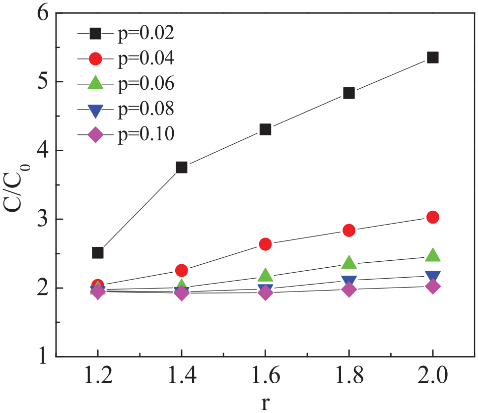
Firstly, the variation of flow characteristics in the tube is analyzed under the effect of the ellipse ratio r with the Reynolds number of 4000. In Figure 6, the response parameter is the relative friction coefficient (relative to the smooth circular helically wound tube R = 1 m, β = 8°), and the influence factor is the ellipse ratio r. It can be seen that the relative friction coefficient increases with the increase of ellipse ratio r for twisted oval tubes with different twisted pitches p. The reason is the high pressure drop caused by the vortex formed behind the dimple, and the increase of ellipse ratio r will increase the pressure drop of the vortex. With the increase of pitch, the number of dimples covered on the surface of the strengthened tube decreases, and the number of induced vortices along the tube reduced, so as to reduce the friction coefficient.
Influence of ellipse ratio r on flow characteristics.
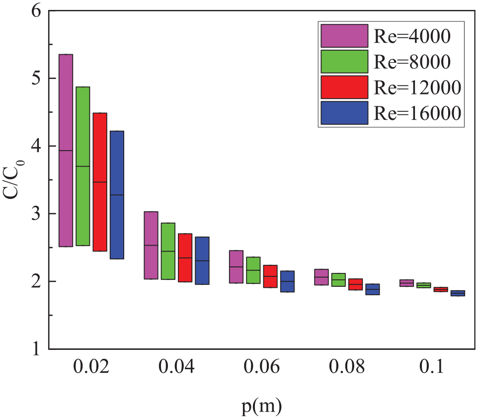
By comparing the variation range of relative friction coefficient with the change of ellipse ratio at different twist pitches, the change law for the influence degree of ellipse ratio on relative friction coefficient at different twist pitch was obtained. Figure 7 shows the variation range of relative friction coefficient with ellipse ratio r under different twisted pitches p when the Re ranges from 4000 to 16,000. When the twisted pitch p is at a high level (p = 0.1 m), the influence of ellipse ratio r on the flow characteristics in the tube is little, while the twisted pitch p is at a low level (p = 0.02 m), the influence of ellipse ratio r on the flow characteristics in the tube is large. The above analysis shows that the interaction effect of twisted pitch p and ellipse ratio r is significant. With the increase of Reynolds number, the influence of ellipse ratio r on the flow characteristics in the tube is weakened.
The variation ranges of relative friction coefficient with ellipse ratio under different twisted pitch.
The influence of groove depth e on the flow characteristics for two-start twisted tube
The variation of flow characteristics for the two-start twisted tube is analyzed under the effect of the groove depth e with the Reynolds number of 4000. In Figure 8, the response parameter is the relative friction coefficient (relative to the smooth circular helically wound tube R = 1 m, β = 8°), and the influence factor is the groove depth e. The influence of the ellipse ratio r on the flow characteristics is consistent with that of the twisted oval mode at different twist pitches p, the relative friction coefficient of the two-start twisted tube increases with the increase of the groove depth e. Similarly, the increase of groove depth e causes more vortex currents behind the dimple, resulting in a higher pressure drop. With the increase of twisted pitch, the number of induced vortices along with the tube decreases, which reduces the friction coefficient.

Influence of groove depth e on flow characteristics.
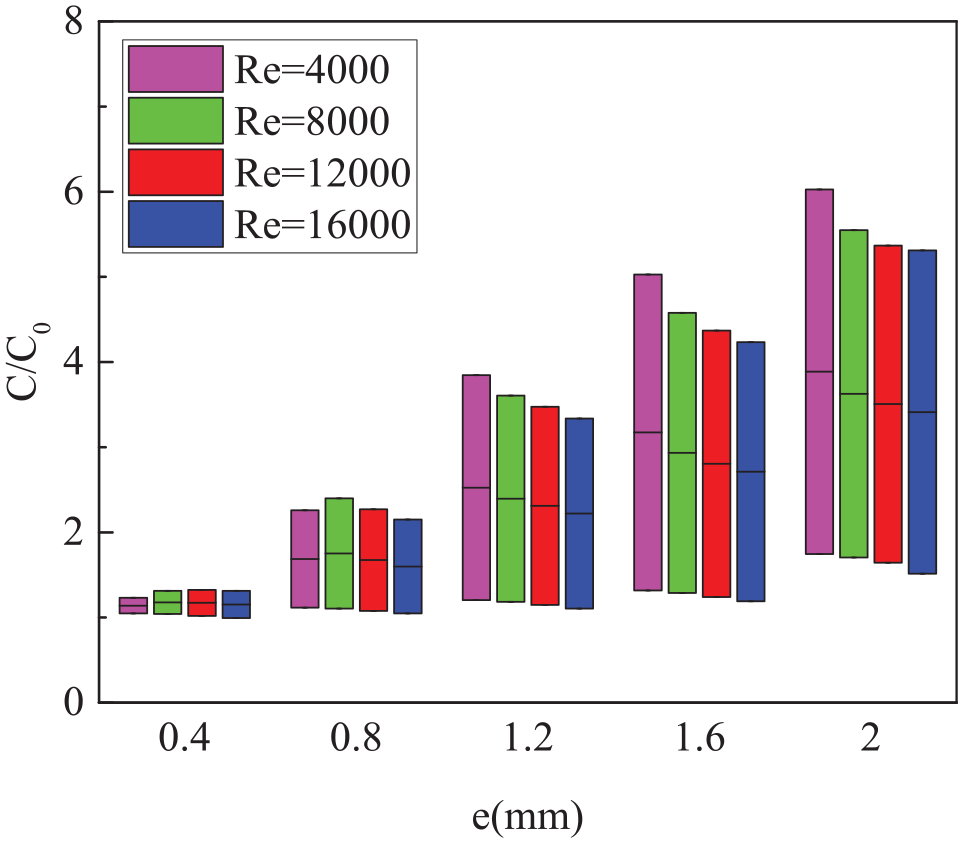
Figure 9 shows the characteristics of the relative friction factor with the groove depth e at different twist pitch p. When the twist pitch is at a high level (p = 0.1 m) and the Reynolds number is 4000, the range of the relative friction factor is 1.05–1.97, and the range of the relative friction factor is 1.00–1.51 when the Reynolds number is 16,000. Therefore, when the twist pitch p is at a high level, the groove depth e has little influence on the flow characteristics in the pipe. When the pitch is at a low level (p = 0.02 m) and the Reynolds number is 4000, the relative friction factor range is 1.23–6.03, and the range of relative friction factor is 1.31–5.31 when the Reynolds number is 16,000. Therefore, the distortion pitch p is at a low level, and the groove depth e has a significant influence on the flow characteristics in the pipe. The above analysis shows that the interaction effect between the twist pitch p and the groove depth e is significant. The influence of the cross section distortion parameters of two kinds of tubes on the relative friction coefficient decreases with the increase of Reynolds number.

The variation range of relative friction coefficient with groove depth under different twisted pitch.
The influence of twisted pitch p on the flow characteristics for two kinds of tubes
The variation law of flow characteristics in the tube under the action of twisted pitch p is shown in Figure 10. The dotted line indicates the twisted oval tube, and the solid line indicates the two-twist twisted tube. When Reynolds number is in the range of 4000–16,000, the relative friction coefficient of two-start twist is lower than that of the twisted oval tube, except for the higher groove depth and ellipse ratio when the twisted pitch p = 0.02 m.

Influence of twisted pitch p on flow characteristics for oval and two-start twisted tubes.
Figure 11 shows the variation of the relative friction coefficient with the twist pitch p at different elliptic ratios and Reynolds number. And the histogram shows the variation range of relative friction coefficient under different twist pitch p from 0.02 to 0.1 m. When the ellipse ratio r is at a low level (r = 1.2), the effect of twist pitch p on the flow characteristics is little. While the ellipse ratio r is at a high level (r = 2.0), the effect of twist pitch p on the flow characteristics is large. The above analysis shows that the interaction effect of twist pitch p and ellipse ratio r is significant. The effect of twisted pitch p on the flow characteristics in the tube decreases with the increase of Reynolds number.

The variation range of relative friction coefficient at different elliptic ratios r.
Figure 12 shows the variation of relative friction coefficient with twist pitch p at different groove depth e. For the interaction effect of the two factors, when the groove depth is at a low level (e = 0.4 mm) and R = 4000, the relative friction coefficient ranges from 1.05 to 1.23. When Reynolds number is 16,000, the relative friction coefficient ranges from 1.00 to 1.31. Therefore, when the groove depth e is at a low level, the twisted pitch p has little effect on the flow characteristics in the pipe. When the groove depth is at a high level (e = 2.0 mm) and R = 4000, the variation range of relative friction coefficient is 1.75–6.03; When the Reynolds number is 16,000, the variation range of relative friction coefficient is 1.51–5.31. Therefore, the twisted pitch p has a great influence on the flow characteristics in the pipe when the groove depth e is at a high level.
The variation range of relative friction coefficient at different groove depth e.
The interaction effect between the two twist parameters and the twist pitch is more significant in the range of the studied working conditions. At different Reynolds number levels, the effect of twisted pitch p on the relative friction factor decreases with the increase of Reynolds number.
Response surface analysis for flow characteristics for two kinds of tubes
Response surface is a cloud map drawn by the higher order formula obtained by fitting the selected factors. Figure 13 shows a response surface with a relative friction factor. The response surface graph can optimize the selected response and the structural parameters to obtain the best response parameters. In the process of optimization, the optimization efficiency can be improved by selecting the fastest descent path. The slope of the optimization path can reflect the change of the influence factors on the response degree during the optimization process. From the interaction effect of factors, the influence of ellipse ratio r on flow characteristics increases with the decrease of twist pitch, and the influence of twist pitch on flow characteristics increases with the increase of ellipse ratio. During the process of optimization, the optimization efficiency can improve by selecting the fastest descent path. The velocity drop path is selected from the response surface of flow characteristics. The influence of the ellipse ratio on the flow characteristics in the tube is weakened in the optimization process at different Reynolds number, and the effect of twist pitch on the flow characteristics in the tube is enhanced.

Response surface plot of flow characteristics for twisted oval tube.
Figure 14 shows the response surface obtained by taking the relative friction factor as a response parameter. It can be seen that the relative friction factor is always greater than 1 in the range of the structural factors studied. From the interaction effect of factors, the influence of groove depth e on flow characteristics increases with the decrease of twist pitch p. The influence of twist pitch p on flow characteristics increases with the increase of groove depth e. When the fastest descent path along the response curve of flow characteristics is optimized at four different Reynolds number levels, the influence of groove depth e on the flow characteristics in the pipe is weakened, while the influence of twist pitch p on the flow characteristics in the pipe is enhanced. Comparing the response surface maps with different Reynolds numbers, it can be seen that with the increase of Reynolds number, the influence of groove depth e and twist pitch p on the flow characteristics in the tube is weakened.

Response surface plot of flow characteristics for two-start twisted tube.
Analysis of the influence of structural parameters on heat transfer characteristics
The influence of elliptic ratio r on the heat transfer characteristics for twisted oval tube
Figure 15 shows the change of relative Nusselt number with the elliptic ratio r under different Reynolds numbers. It can be seen that when the Reynolds number range is 4000–16,000, the relative Nusselt number of the twisted helically tubes with different twist pitch p increases with the increase of the elliptic ratio r. By increasing the elliptic ratio r, a higher number of dimples cover the tube surface, so the area with increased velocity and local heat transfer will be increased. In addition, the rotation of the fluid along the pipe is relatively increased. So the relative Nusselt number increase with the increase of the elliptic ratio r.
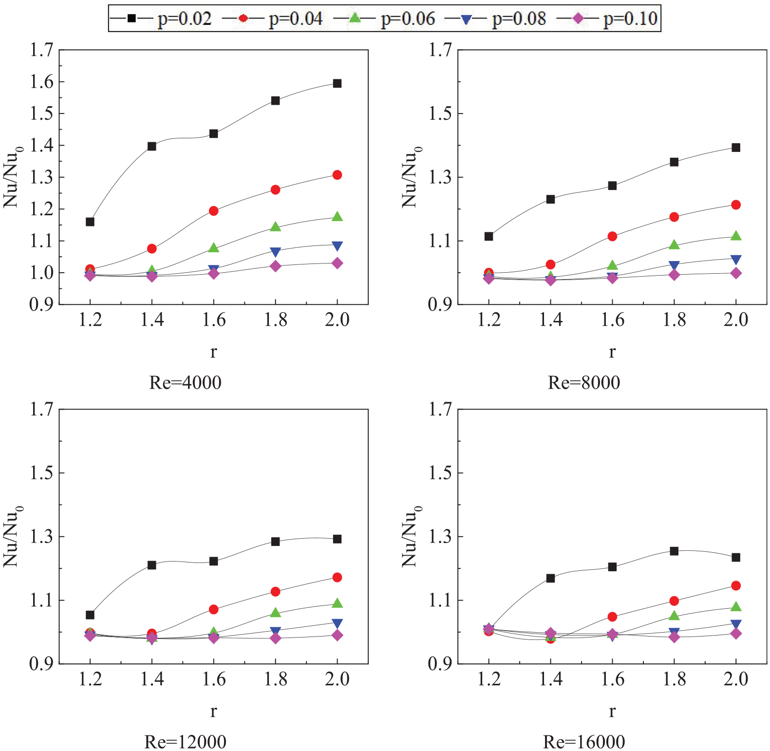
Influence of twist ratio on heat transfer characteristics in twisted oval tube.
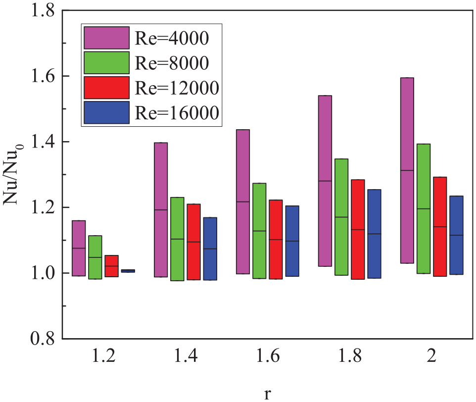
When the ellipse ratio r changes in a fixed range, the fluctuation amplitude of the heat transfer coefficient is different due to the level of twisted pitch p, which indicates that there is an interaction between the two factors. Figure 16 shows the variation of relative Nusselt number with ellipse ratio at different twist pitch p. When the twist pitch is at a high level (p = 0.10 m), the relative Nusselt number ranges from 0.99 to 1.03 when the Reynolds number is 4000. In addition, the relative Nusselt number ranges from 0.98 to 1.00 when the Reynolds number is 16,000. Therefore, when the twist pitch is high, the ellipse ratio r has little effect on the heat transfer characteristics. The relative Nusselt number ranges from 1.16 to 1.59 when Reynolds number is 4000, and from 1.01 to 1.25 when Reynolds number is 16,000. The above analysis shows that the interaction effect of twisted pitch p and ellipse ratio r is significant. With the increase of Reynolds number, the influence of ellipse ratio r on the heat transfer characteristics in the tube decreases.

The variation range of relative Nusselt number with ellipse ratio under different twisted pitch.
The influence of groove depth e on the heat transfer characteristics for two-start twisted tube
In Figure 17, the response parameter is the relative Nusselt number, and the influence factor is the groove depth e. When Reynolds number ranges from 4000 to 16,000, the influence of ellipse ratio r on heat transfer characteristics is consistent with that of twisted oval mode at different twist pitches p. The relative Nusselt number of two-start twisted mode increases with the increase of groove depth e. This is mainly because the thermal boundary layer in the twisted tube is destroyed and a large temperature gradient is formed near the wall of the two-start twisted tube with the groove depth e increased. Therefore, compared with the smooth tube, the twisted tube increases the total heat transfer rate.

Influence of groove depth e on heat transfer characteristics in two-start twisted tube.
Figure 18 shows the variation of relative Nusselt number with groove depth e under different twisted pitch p. When the twist pitch is at a high level (p = 0.10 m) and Reynolds number is 4000, the range of relative Nusselt number is 1.01–1.02; When Reynolds number is 16,000, the range of relative Nusselt number is 1.01–1.02. Therefore, when the twist pitch is at a high level, the groove depth e has little effect on the heat transfer characteristics in the tube. When the twist pitch is at a low level (p = 0.02 m), the groove depth e has a great influence on the heat transfer characteristics in the tube. The above analysis shows that the interaction effect of twisted pitch p and groove depth e is significant. By comparing the variation of different Reynolds number levels, it can be concluded that the influence of groove depth on the relative Nusselt number decreases with the increase of Reynolds number.

The variation range of relative Nusselt number with groove depth under different twisted pitch.
The influence of twisted pitch p on the heat transfer characteristics for two kinds of tubes
Figure 19 shows the variation of relative Nusselt number (R = 1 m, β = 8° relative to helically wound tube) with twisted pitch p. The dotted line shows heat transfer characteristics of twisted oval mode, while the solid line shows the variation of heat transfer characteristics of the two-start twisted mode. The results show that the influence of twisted pitch p on the heat transfer characteristics is consistent with that on the flow characteristics, and the relative Nusselt number of twisted pitch p is higher than that of the twisted oval.

Influence of twisted pitch p on heat transfer characteristics for oval and two-start twisted tubes.
Figure 20 shows the range of relative Nusselt number with the change of twist pitch p at different ellipse ratio r. When the ellipse ratio is at a low water level (r = 1.2), and the Reynolds number is 4000, the range of relative Nusselt number is 0.99–1.16; when the Reynolds number is 16,000, the range of relative Nusselt number is 1.00–1.01. Therefore, when the ellipse ratio r is low, the twisted pitch p has little effect on the heat transfer characteristics in the tube. When the Reynolds number is 16,000, the relative Nusselt number ranges from 1.00 to 1.23. Therefore, when the ellipse ratio is at a high level, the twisted pitch p has a great influence on the heat transfer characteristics in the tube. At different Reynolds number, with the increase of Reynolds number, the effect of twisted pitch p on the heat transfer characteristics in the tube is weakened.
The variation range of relative Nusselt number at different ellipse ratio for twisted oval tube.
Figure 21 shows the variation of relative Nusselt number with twist pitch p at different groove depth e.

The variation range of relative Nusselt number at different groove depth e for two-start twisted tube.
When Reynolds number Re is in the range of 4000–16,000, the heat transfer characteristics of the two types of enhanced tubes are basically the same: the relative Nusselt number decreases with the increase of twisted pitch p, and the effect of twisted pitch p on the heat transfer characteristics of the two-start twisted tube is greater than that of the twisted oval tube. For the interaction effect of the two factors on the heat transfer characteristics, when the groove depth e is at a low level (e = 0.4 mm) and Reynolds number is 4000, the relative Nusselt number ranges from 1.00 to 1.09, and when Reynolds number is 16,000, the relative Nusselt number ranges from 1.01 to 1.11. Therefore, the effect of twisted pitch p on the heat transfer characteristics in the tube is small when the groove depth e is at a low level. Meanwhile, when the groove depth e is at a high level (e = 2.0 mm) and Reynolds number is 4000, the relative Nusselt number ranges from 1.18 to 2.06, and the relative Nusselt number ranges from 1.01 to 1.74 when Reynolds number is 16,000. Therefore, the twist pitch p has a greater impact on the heat transfer characteristics in the tube when the groove depth e is at a high level. The interaction effect with groove depth e is significant. At different Reynolds number Re levels, the effect of twisted pitch p on the relative Nusselt number decreases with the increase of Reynolds number.
Response surface of heat transfer characteristics for oval and two-start twist tube
Figure 22 shows the response surface plot of the effect of ellipse ratio r and twist pitch p on the Nu/Nuo. When the relative Nusselt number is greater than 1, the heat transfer is enhanced. It can be seen that the region where the heat transfer coefficient decreases expand with the increase of Reynolds number. From the interaction effect of factors, the influence of ellipse ratio r on heat transfer characteristics is enhanced with the decrease of twist pitch p. Meanwhile, the influence of twist pitch p on heat transfer characteristics is enhanced with the increase of ellipse ratio r. According to the response surface of heat transfer characteristics, the steepest descent path is selected. Under four different Reynolds number levels, the influence of ellipse ratio r on the heat transfer characteristics in the tube is enhanced, while the influence of twisted pitch p on the heat transfer characteristics in the tube is weakened. In addition, with the increase of Reynolds number, the influence of ellipse ratio r and twisted pitch p on the heat transfer characteristics in the tube decreases.

Response surface plot of heat transfer characteristics in twisted oval tube.
Figure 23 shows the response surface of heat transfer characteristics in a two-start twisted tube. It can be seen that the relative Nusselt number is always greater than 1 in the range of structural factors studied. From the interaction effect of factors, the influence of groove depth e on heat transfer characteristics increases with the decrease of twisted pitch p. Meanwhile, with the increase of groove depth e, the influence of twisted pitch p on heat transfer characteristics is enhanced. The response surface diagram can be used to optimize the selected response. At four different Reynolds number levels, the effect of groove depth e on the heat transfer characteristics in the tube increased, while the effect of twisted pitch p on the heat transfer characteristics in the tube weakened. Comparing the response surfaces at different Reynolds numbers, it can be seen that the influence of groove depth e and twisted pitch p on the heat transfer characteristics in the tube decreases with the increase of Reynolds number.

Response surface plot of heat transfer characteristics in two-start twisted tube.
Analysis of the influence of structural parameters on comprehensive strengthening characteristics
The influence of elliptic ratio r on the comprehensive strengthening characteristics for twisted oval tube
A thermal enhancement factor TEF was used for evaluating the enhancement heat transfer. Figure 24 shows the variation of TEF with ellipse ratio r at different Reynolds numbers. When the Reynolds number are 4000 and 8000, the TEF increases with the increase of ellipse ratio r. The main reason is that the secondary flow intensity in the tube changes along the flow direction, twisted tube destroys the thermal boundary. With the increase of ellipse ratio r, a larger temperature gradient will be generated near the twisted tube wall. Therefore, the total heat transfer rate increases with the increase of ellipse ratio r. The enhancement ratio of enhanced heat transfer is greater than that of friction loss at low Reynolds number and enhanced heat transfer is dominant. When the Reynolds number are 12000 and 16,000, the change of TEF with ellipse ratio r is relatively smooth. In common, the thermal boundary layer becomes thinner as Reynolds number increases. Therefore, the effect of ellipse ratio in promoting the boundary layer disruption at a higher Reynolds number is no significant than that at a lower Reynolds number. The influence of the ellipse ratio on the TEF is different from the flow and heat transfer characteristics. The final calculation value of TEF changes little, and there are still small fluctuations under different structural parameters.

Influence of ellipse ratio on comprehensive strengthening characteristics in twisted oval tube.
Figure 25 shows the variation of TEF with ellipse ratio under different twisted pitch p. When the twist pitch is at a high level (p = 0.1 m) and Reynolds number is 4000, the TEF varies from 0.79 to 0.81, while the Reynolds number is 16,000, the TEF ranges from 0.81 to 0.82. Meanwhile, when the pitch is at a low level (p = 0.02 m) and Reynolds number is 4000, the range of TEF is 0.85–0.91, while the Reynolds number is 16,000, the range of TEF is 0.76–0.80. Moreover, with the increase of Reynolds number, the influence of the ellipse ratio on the TEF is weakened.

The variation range of TEF under different twist pitch p for twisted oval tube.
The influence of groove depth e on the comprehensive strengthening characteristics for two-start twisted tubes
Figure 26 shows the variation of TEF with groove depth e at different Reynolds numbers. It can be seen that the TEF of low groove depth is the largest at Reynolds number of 4000 and 8000, and the TEF of p = 0.1 m decreases with the increase of groove depth. When Reynolds number are 12,000 and 16,000, TEF changes gently with the groove depth e.

Influence of groove depth e on TEF for two-start twisted tube.
Figure 27 shows the variation range of TEF with groove depth under different twisted pitch p. When the twist pitch is at a high level (p = 0.1 m) and the Reynolds number is 4000, the TEF varies from 0.94 to 0.98. When Reynolds number is 16,000, TEF ranges from 0.88 to 1.01, while pitch is at low water level (p = 0.02 m) and Reynolds number is 4000, TEF ranges from 1.02 to 1.13. When Reynolds number is 16,000, TEF ranges from 0.95 to 1.01. The influence of the interaction effect on different Reynolds number levels is different. With the increase of Reynolds number, the range of TEF increases at high pitch p.

The variation range of TEF with groove depth under different twist pitch p.
The influence of twisted pitch p on the comprehensive strengthening characteristics for two kinds of tubes
Figure 28 shows the variation characteristics of TEF with pitch p at different Reynolds numbers. In the figure, the dotted line represents the twisted oval tube, and the solid line represents the variation law of the two-start twist tube. At different Reynolds number levels, the TEF of a two-start twisted tube is higher than that of twisted oval tube, which indicates that a two-start twisted tube is more suitable for heat transfer enhancement of helical tube. When the Reynolds number is 4000 and 8000, the heat transfer characteristics of the two kinds of enhanced tubes are basically the same. The reason is that the effect of twisted pitch p in promoting the boundary layer disruption at lower Reynolds number is significant. At lower Reynolds number, the boundary layer is thicker, and the vortex caused by the strengthened structure enhances the heat transfer effect of the two kinds of strengthened tubes. In addition, the TEF decreases with the increase of twisted pitch p, and the influence of twisted pitch p on the heat transfer characteristics of the twisted tube is greater than that of the twisted oval tube. With the increase of Reynolds number, the change of other TEF with pitch p is little for the two kinds of tubes, except for the extreme value of TEF at high r = 2.
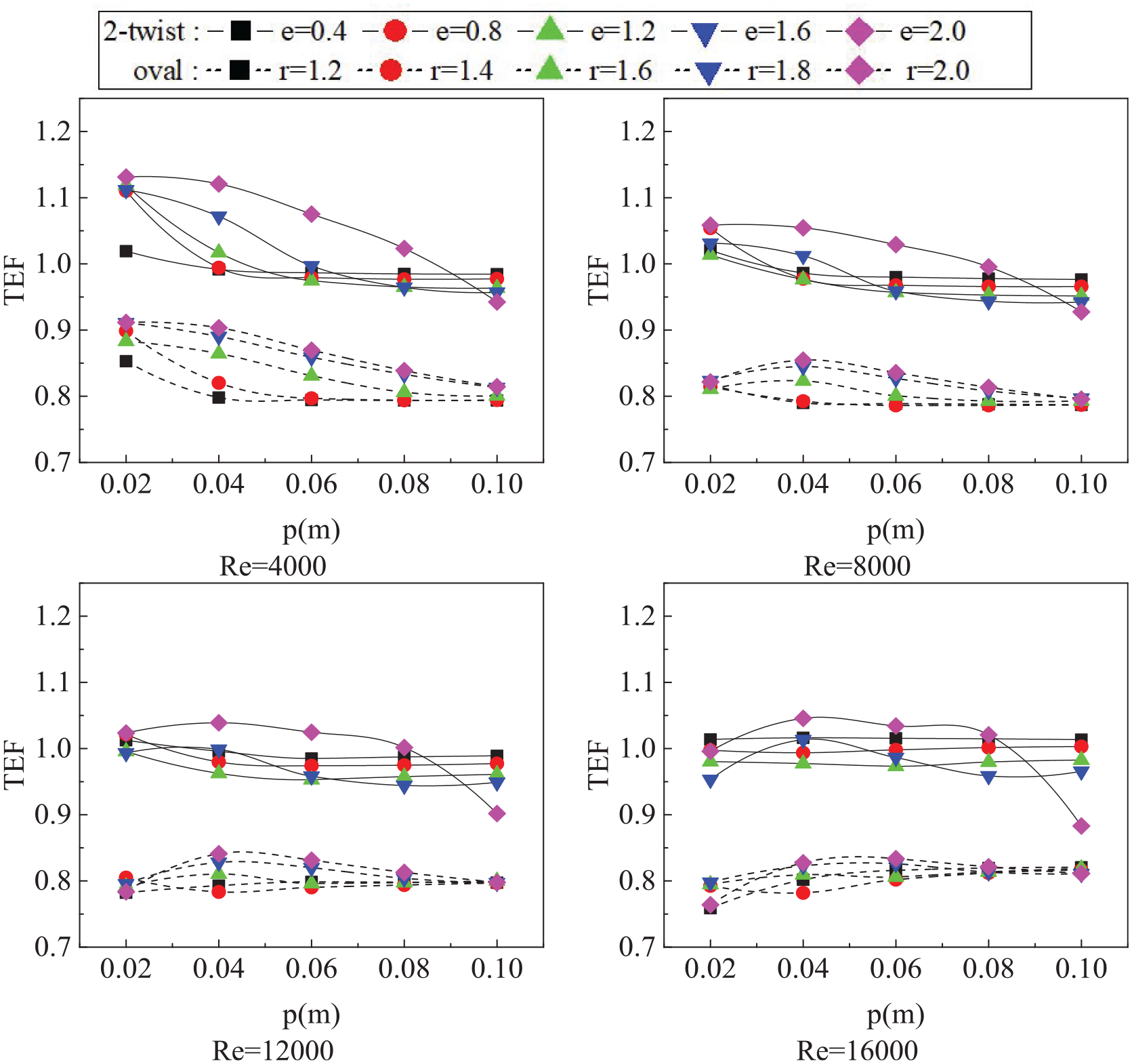
Influence of twist pitch p on TEF for oval and two-start twisted tubes.
Figure 29 shows the variation range of TEF with twist pitch p under different ellipse ratio r. When the ellipse ratio is 1.2 and the Reynolds number is 4000, the TEF ranges from 0.79 to 0.85. When the Reynolds number is 16,000, the TEF ranges from 0.76 to 0.82. Meanwhile, with the change of twist pitch p, when the ellipse ratio is 2.0 and the Reynolds number is 4000, the TEF ranges from 0.81 to 0.91. When the Reynolds number is 16,000, the TEF ranges from 0.76 to 0.83. It shows that the influence of twist pitch p on the comprehensive strengthening characteristics decreases with the increase of Reynolds number. Figure 30 shows the variation range of TEF with twist pitch p at different groove depth e. When the groove depth e is at a low level (e = 0.4mm) and Reynolds number is 4000, the range of TEF is 0.98–1.02. When Reynolds number is 16,000, the range of comprehensive enhancement factor TEF is 1.01–1.02. With the change of twist pitch p, when the groove depth e is at a high level (e = 2.0 mm) and Reynolds number is 4000, the TEF ranges from 0.94 to 1.13, and Reynolds number is 16,000, the TEF ranges from 0.88 to 1.05. The maximum enhancements factor TEF of 1.1312 is obtained with a groove depth of 2.0, the twisted pitch of 0.02, and Reynolds number of 4000 for the two-start twisted tube. It shows that the influence of cross-section distortion parameters of the two strengthening modes on the TEF decreases with the increase of Reynolds number.

The variation range of TEF at different elliptic ratio r for twisted oval tube.

The variation range of TEF at different groove depth e for two-start twisted tube.
Mechanism analysis of enhanced heat transfer and modified correlation
Figure 31 shows the streamline diagram, local friction coefficient diagram and local heat transfer coefficient diagram of the twisted tube. There are three types of fluid flow patterns near the wall: periodic helically flow consistent with the deformation period of the wall (streamline a); periodic helically flow inconsistent with the deformation period of the wall (streamline b); part of the fluid cannot be induced into helically flow, which scours the protruding wall, resulting in backflow near the wall of the depression (streamline c).
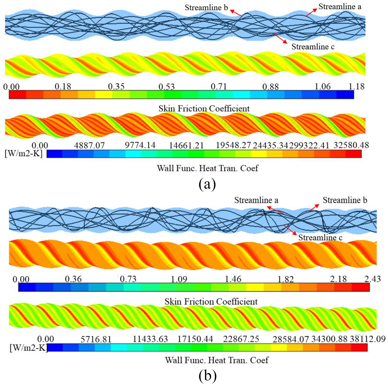
Streamline diagram, local friction coefficient diagram and local heat transfer coefficient diagram: (a) twisted oval tube and (b) two-start twisted tube.
The periodic deformation of the wall makes the local friction coefficient of the tube wall have periodic distribution along the length. When the fluid washes the wall, there is a backflow in the concave part of the wall, which intensifies the dissipation of fluid energy and increases the local friction coefficient of the concave part. With the increase of ellipse ratio r, the degree of pipe walls depression increases, the fluid is easier to produce backflow, and the friction coefficient increases. In addition, with the decrease of twist pitch p, the depression per unit distance increases, and the friction coefficient increases. The periodic deformation of the wall makes the local heat transfer coefficient near the tube wall have periodic distribution along the tube length. When the fluid washes the wall, there is a backflow at the concave part of the pipe wall, which slows down the mixing of fluids and deteriorates the heat transfer. Meanwhile, when the fluid washes the wall at the protruding part of the pipe wall, the boundary layer becomes thinner and the heat transfer is enhanced. In different regions of the tube wall, the degree of deformation of the tube wall is different, and the degree of fluid flow disturbance is also different. The results show that the enhanced heat transfer effect of boundary layer thinning is stronger than that of backflow deterioration caused by wall depression, and the area of heat transfer effect will gradually increase. The average heat transfer coefficient will increase.
The applicable range of the empirical formula for the twisted oval tube is as follows: the range of ellipse ratio r is 1.2–2.0, the range of twist pitch p is 0.02–0.1 m, the range of helix angle β is 8°–12° and the range of winding radius R is 1–1.4 m. According to the simulation results, the formula of friction coefficient of elliptical twisted helically wound pipe is as follows:

The formula of Nusselt number for the elliptical twisted helically wound tube is:

The applicable range of formula for the two-start twisted tube is as follows: the range of groove depth e is 0.4–2.0 mm, the range of twist pitch p is 0.02–0.1 m, the range of helix angle β is 8°–12°, and the range of winding radius R is 1–1.4 m. According to the simulation results, the formula of friction coefficient of the two-start twisted helically wound tube is as follows:

The formula of Nusselt number for the two-start twisted tube is:

The above square values of the coefficients determined by the fitted formula are greater than 0.9. The formula of comprehensive enhancement factor is calculated by using the above formula of flow and heat transfer, which can analyze the comprehensive enhancement characteristics.
Conclusions
The effects of significant factors on the flow and heat transfer characteristics of twisted oval and two-start twisted helically wound tubes are studied by numerical simulation. The influence of distortion pitch p and cross section deformation parameters and their interaction on the flow characteristics, heat transfer characteristics, and comprehensive strengthening characteristics of the tube are analyzed at different Reynolds number. In the range of simulation conditions, the formulas of flow and heat transfer were obtained. The main conclusions are as follows:
The relative friction coefficients and Nusselt number of the two kinds of strengthened tubes increase with the increase of the section deformation parameters, and decrease with the increase of the twist pitch p. With the increase of Reynolds number, the effects of twist pitch p and cross-section deformation parameters on the flow characteristics in the tube decrease.
Compared with twisted oval helically wound tube, the comprehensive strengthening effect of two-start twisted helically wound tube is better than that of the helically wound tube without strengthening, the thermal enhancement factor about 0.94–1.13 times in Re = 4000 and 0.88–1.05 times in Re = 16,000 higher than those of the smooth tube, respectively.
The influence of twist pitch p on the comprehensive strengthening characteristics is weakened with the increase of Reynolds number for twisted oval tube, while the effect of cross-section distortion parameters of the two strengthening modes on the comprehensive strengthening factor decreases with the increase of Reynolds number for two-start twisted tube.
The maximum enhancements factor TEF of 1.1312 is obtained with a groove depth of 2.0, the twisted pitch of 0.02, and Reynolds number of 4000 for the two-start twisted tube.
The formulas of flow and heat transfer of twisted oval and two-start twisted helically wound tubes are proposed.
Footnotes
Appendix
Handling Editor: Chenhui Liang
Declaration of conflicting interests
The author(s) declared no potential conflicts of interest with respect to the research, authorship, and/or publication of this article.
Funding
The author(s) disclosed receipt of the following financial support for the research, authorship, and/or publication of this article: This work was supported by the research funds from National Natural Science Foundation of China (Grant No. 52106061); Natural Science Foundation of Zhejiang Province of China (Grant No. LQ20E060010); Department of Education of Zhejiang Province of China (Grant No. Y201942156).