
Abstract
To address the low adhesion issue caused by contaminants such as water or oil entering the wheel-rail interface, high-speed rail vehicles utilize sanding devices to improve adhesion. This method effectively mitigates most low-adhesion conditions. However, subway vehicles currently lack sanding devices, leading to extended braking distances, wheel slip, and even collisions under low-adhesion conditions. This paper systematically investigates the wheel-rail adhesion change and the braking performance under the influence of sanding, aiming to explore the necessity of adding sanding devices to subway vehicles. Laboratory tests were conducted using a 1:4 circumferential test rig, which mimics the field lines, establishing an equivalence between the actual vehicle and laboratory conditions. The study also analyzed the deterioration of the sanding effect between Axles under three conditions: water, oil, and an oil/filings mixture. A subway braking/anti-slip simulation platform was developed, incorporating sanding deterioration, to evaluate the train braking performance under different sanding amount. Finally, the paper provides reasonable recommendations for the optimal installation positions of sand devices on subway vehicles.
Introduction
Rail transit vehicles rely on the wheel-rail interaction for traction, braking, and guidance. Under complex real line conditions, the rail surface is often affected by third bodies such as water, oil, leaves, and ice/snow,1–8 leading to insufficient wheel-rail adhesion. This results in increased braking distances, which significantly impacts the safe operation of trains. Sanding, as the most commonly used method to overcome low adhesion, has been widely applied on high-speed trains.9,10 However, many subway vehicles are not routinely equipped with sanding devices due to a combination of environmental and operational concerns. Compared to high-speed or intercity trains, subway trains operate under significantly different conditions: (1) they require higher braking deceleration due to shorter station spacing, (2) they undergo frequent acceleration and deceleration cycles, and (3) they run primarily in enclosed tunnels, where sand dispersion can interfere with signaling equipment and increase maintenance demands. These operational distinctions make subway systems more vulnerable to wheel slip and braking failure under low adhesion conditions. For example, Shanghai Metro Line 16 regularly experiences wheel sliding and signal overruns due to low adhesion, and in late 2023, a rear-end collision occurred on Beijing’s Changping Line due to icy track conditions. 11 Similarly, in Europe, subway vehicles often experience delays or even collisions in autumn due to fallen leaves.12–14 To further ensure the safe operation of subway, it is essential to investigate the necessity of equipping subway vehicles with sanding devices under low-adhesion conditions.
Research on sanding for adhesion enhancement has become relatively abundant internationally. Wheel-rail experimental studies under low-adhesion conditions have shown that factors such as sanding amount, type of sand, and grain size directly affect the effectiveness of adhesion enhancement. On the other hand, factors like train speed, crosswind, and sanding angle influence the distribution of sand on the track surface, which in turn determines the particle density in the actual wheel-rail contact interface. These two factors are intertwined, making the actual sanding process influenced by multiple variables. Regarding the former, scholars have used small-scale test rigs to simulate the wheel-rail adhesion behavior under sanding conditions. Wang et al.9,15 conducted wheel-rail adhesion characteristic tests using an MMS-2A friction and wear test machine to study the effect of sanding on improving the adhesion coefficient under water and oil contamination conditions. Shi et al.16,17 discovered through JD-1 test rig that the particle distribution density on the track surface has the most significant impact on adhesion enhancement, with a threshold value of 0.607 g/m. Before reaching this threshold, the wheel-rail adhesion coefficient increases significantly with more sanding amount; after surpassing the threshold, the adhesion coefficient stabilizes. Kumar et al. 18 confirmed through experiments that the adhesion coefficient is closely related to the amount of sanding. Omasta et al. 19 conducted sanding tests on small-scale test rigs and found that only under low slip and low-speed conditions does the change in sanding amount have an effect on restoring wheel-rail adhesion. Regarding the latter, related research is still in its early stages. Recently, Wang et al. 20 designed and developed a full-scale wheel-rail sanding simulation device to simulate the sanding process in indoor conditions under different train speeds, wind velocity, types of sand particles, and sanding parameters.
Due to the inherent characteristics of real trains, such as long formations, multiple wheelsets, and operation on fixed tracks, significant variations in the sanding adhesion enhancement effect are observed between individual axles. Typically, the axle where sanding is applied experiences a sharp increase in adhesion, while the adhesion enhancement effect on subsequent axles progressively diminishes from the initial axle. Knorr through bench testing, has established the relationship between sanding-induced adhesion increments, sanding amount, and axle position, thereby demonstrating the phenomenon of inter-axle deterioration in the sanding effect. 21 Some research16,17 have also indicated that the duration of the adhesion enhancement achieved by sanding reflects the ability of hard particles applied to the track surface to meet the adhesion requirements of subsequent wheelsets. This metric can, therefore, be used to inform the distribution of sanding devices in terms of both their quantity and axle positions on the train. However, it is important to note that excessive sanding is not always advantageous. According to the GMRT2461 standard established by the British Railway Commission, the maximum allowable sanding amount is capped at 7.5 g/m, 22 beyond which electrical insulation between the wheel and rail may be compromised, potentially leading to operational issues. Therefore, the key challenge lies in optimizing the sanding effect within the constraints of the prescribed sanding limits. Fieberg 23 has demonstrated that variable-speed sanding systems yield different outcomes in terms of improving adhesion under low-adhesion conditions and has suggested the use of dual-speed sanding devices as a solution to address autumnal adhesion challenges. Furthermore, Hu et al. 24 have analyzed the latest advancements in sanding device technology and, based on these findings, forecast the future trajectory toward intelligent, precision-controlled, and integrated sanding devices.
In summary, current research on wheel-rail sanding primarily focuses on the effects of sanding amount, particle size, and sanding speed on the adhesion of individual wheels, with little attention given to the overall adhesion enhancement for entire trains. Furthermore, most studies have concentrated on high-speed trains. Given the braking challenges faced by subway vehicles under low-adhesion conditions, it is essential to conduct a comprehensive investigation into the inter-axle sanding adhesion deterioration patterns and the subsequent improvement in braking performance after sanding intervention. Such research would provide valuable guidance for the installation of sanding devices on subway vehicles.
Experimental test on the deterioration performance of sanding
Principle of test rig
To determine the optimal installation positions for sanding devices on subway vehicles, it is first necessary to conduct an experimental study on the inter-axle deterioration performance of sanding. This study primarily relies on experimental investigations to assess the effectiveness of sanding in improving wheel-rail adhesion. While theoretical modeling offers valuable insights, it is insufficient for capturing the full complexity of sanding effects, which are inherently tribological in nature. In tribological studies, the type and thickness of third-body layers at the wheel-rail interface play a dominant role in determining adhesion performance.
A circumferential wheel-rail test rig25,26 was used in this study, as shown in Figure 1. The main feature of this test rig is its wheel/ring mechanical structure, which utilizes a fixed track and a rotating arm to drive the wheel’s rotation. This configuration allows the third-body contaminants and applied sand to remain attached to the stationary track surface, thereby preventing the loss of contaminants due to centrifugal force from the wheel in traditional wheel/wheel test rigs. This mechanical construction better simulates the dynamic and static conditions of wheel-rail contact. The test rig uses a 1:4 scale model of the wheel, with a wheel diameter of 210 mm and a circular track diameter of 2 m. The wheel-rail contact on the scaled test rig was constructed based on the Hertz equivalent principle to ensure that the stress distribution within the contact patch of the scaled wheel-rail matches that of the real one. The experimental results presented in this study primarily serve the braking and anti-slip control of trains on straight tracks. Therefore, greater attention is given to the wheel-rail friction coefficient rather than the influence of contact surface geometry, with non-Hertzian or dual-point contact behaviors caused by lateral wheel displacement not being considered.
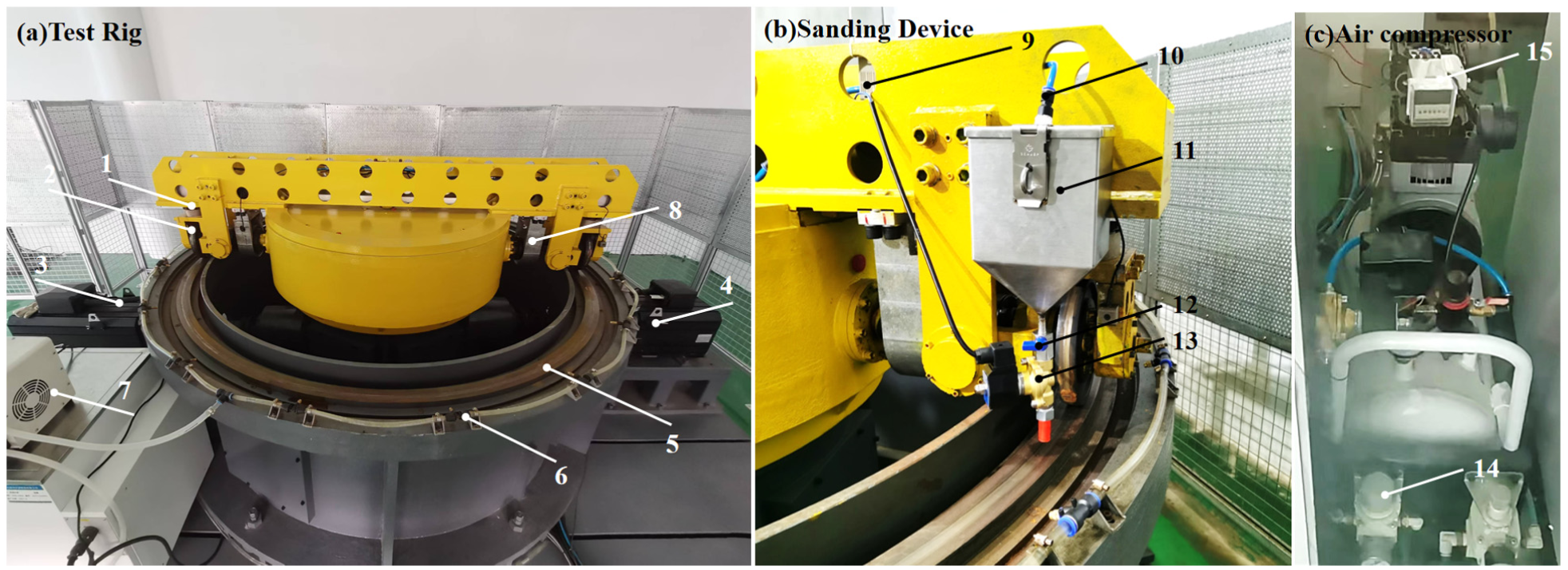
Circumferential wheel-rail test rig: (a) test rig, (b) sanding device, and (c) air compressor.
The mechanical structure of the circumferential wheel-rail test rig primarily consists of a frame, cover, rotating arm, wheels, track, fluid spraying device, motor, and the internal drive mechanism within the frame. To simulate the sanding behavior of real trains, a scaled sanding device is installed on one side of the rotating arm of the circumferential wheel-rail test rig (Figure 1). The scaled sanding device includes components such as a sand box, solenoid valve, pressure regulator, air compressor, and flow control valve. The air compressor delivers compressed air to the sand box, which is then connected to the sand box through solenoid valves and pressure regulators controlled by a timer. Under the action of compressed air, the sand inside the sand box is lifted, and the sanding flow is controlled by an electric ball valve, thereby achieving the sanding function.
The test rig adopts a differential dual-reduction gear structure, with two motors installed to independently control the rotating arm speed (simulating train speed) and the wheel rolling speed. The speed motor for the train simulates the forward motion of the train on the track by driving the rotating arm in the horizontal plane (rotational motion of the rotating arm), while the wheel speed motor controls the wheel’s rotational speed in the vertical plane of the track to simulate the rolling speed on the track surface (wheel rotation). The difference in the speeds of these two motors generates the slip ratio. A torque sensor is installed on the wheel axle to measure the wheel speed (wheel rotational speed) and the wheel-rail tangential force. An encoder located at the output shaft of the train speed motor allows the calculation of the current train speed (rotating arm speed). A cylinder is mounted at the end of the rotating arm, with a pressure sensor located below it. By injecting compressed air into the cylinder, axle load simulation is achieved. This test rig facilitates the collection of train speed


Equivalence of sanding amount
The sand used in the experiment is quartz sand, with a density equivalent to that of the sand used in real train applications. The sanding amount was adjusted for mass equivalence, with a scaling factor of 1:43 applied to the 1:4 scaled test rig. According to the relevant standards,27,28 when sanding at a pressure of 450 kPa, the sanding amount should range from 500 to 1000 g/30s. Based on the methodology from the Knorr research report and to eliminate the influence of train speed on the test results, this experiment uses a sanding amount measurement in g/m. 21 The equivalent sanding amounts are shown in Table 1. On the circumferential test rig, a sanding amount of 0–0.3 g/m fully covers the range of sanding amounts used in real trains. For real trains, a sanding amount of 1000 g/30s exceeds the spraying limit of the sanding device.
Equivalent sanding amounts.

Equivalence of different axle positions
Due to the circumferential structure of the test rig, the wheel located at the end of the rotating arm is able to roll continuously on the circular track, allowing each full rotation of the wheel to pass the same point on the track. This method enables the simulation of the sanding-induced adhesion decay effect across multiple axles on the train. On this test rig, the axle position is converted into the number of wheel rolling cycles, as shown in Figure 2.

Equivalent method for axle position on the test rig.
At an equivalent speed of 40 km/h, the wheel completes one full rotation cycle on the circular track in 2.5 s, meaning that four axles pass the fixed point on the test rig’s track within 10 s. Therefore, the positions of different axles on the real train can be correlated with the wheel’s rolling cycles on the test rig, with the equivalent relationship shown in Table 2.
Equivalence of axle position and wheel rolling cycles (40 km/h).

Experimental procedure
Based on the circumferential wheel-rail test rig equipped with sanding devices, a study on the sand deterioration performance under low-adhesion conditions is conducted. The test rig applies an equivalent axle load of 11 tons, representative of the typical static axle load for subway vehicles under the AW0 condition. The experimental procedure is as follows:
(1) A low-adhesion rail surface with three artificial contaminant conditions was created: water, oil, and an oil/iron filings mixture. The water condition was achieved using the test rig’s built-in spraying device at a rate of 1 L/min. For the oil condition, 40 mL of 75W-90 lubricant was evenly applied to the track surface. The oil and iron filings mixture was prepared by blending 20 mL of oil with 20 mL of iron filings, and then evenly spreading the mixture on the rail surface.
(2) Load an equivalent axle weight of 11 t, activate the test rig, and accelerate to the target equivalent speed of 40 km/h. Set the wheels to operate at a 5% slip ratio.
(3) Set the sanding device’s sanding amount, open the solenoid valve to begin sanding, and allow the sanding device to complete a full cycle before closing the sanding solenoid valve to ensure even distribution of sand along the track. Conduct the adhesion test, and collect parameters such as wheel-rail speed and torque to obtain curves showing the variation of adhesion coefficient with time and wheel cycles.
(4) Clean the track surface with industrial dishwashing detergent, and once the surface has completely dried, reapply the third body layer and begin the next test.
Analysis of sanding deterioration performance
Water condition
Water, as a common contaminant on rail surfaces, often arises from rainfall, dew, or other weather-related factors, leading to a thin water film on the rail and resulting in low adhesion conditions. 1 Some theoretical analyses indicate that water can form a film on the rail surface, thereby reducing the friction coefficient between the wheel and rail. 4 This study conducted wheel-rail adhesion tests under water conditions with varying sand application rates, as illustrated in Figure 3. When the sand application rate was 0 g/m, the adhesion coefficient between the wheel and rail remained around 0.15, which can be considered the natural adhesion characteristic under water conditions. With a sand application rate of 0.05 g/m, the adhesion coefficient immediately rose to 0.19 after sanding, followed by a gradual decline as more wheelsets passed. This indicates that the effect of sanding does not last indefinitely, it diminishes as the wheels continue to roll over the sanded surface. During the wheel’s compression of quartz sand, vibration inevitably occurs in the wheel-rail system due to the presence of sand particles at the contact interface. This vibration leads to fluctuations in the recorded adhesion coefficient, especially noticeable shortly after sanding. Over time, the quartz sand particles break down under the repeated rolling of the wheels, transitioning from larger grains to a powdery form, and mixing with the water to form a milky suspension. At this stage, both the amplitude of adhesion fluctuations and the degree of adhesion improvement decrease. As the sand application rate increases, the degree of adhesion enhancement also grows. Sand application rates of 0.1, 0.15, and 0.2 g/m resulted in maximum adhesion coefficients of approximately 0.22, 0.24, and 0.28, respectively. The higher the sand application rate, the more gradual the decrease in adhesion with increasing number of wheel passes. There is a saturation point for sand application, excessive sand does not infinitely increase adhesion. In the experiments, both 0.3 and 0.2 g/m sand application rates raised the adhesion to around 0.28, although the 0.2 g/m exhibited a slightly faster decline in adhesion effectiveness during subsequent wheel rolling compared to the 0.3 g/m.

Adhesion enhancement with sanding under water conditions: (a) 0.2 g/m, (b) 0.3 g/m, and (c) water condition.
The study indicates that under water conditions, sanding can significantly enhance adhesion. As quartz sand is compressed by the wheels, it gradually breaks down into finer particles and is pushed out of the contact patch, leading to a decline in adhesion as more axles pass over the track. However, without sanding, the adhesion coefficient in water conditions is already above 0.15, which is sufficient to exceed the deceleration required for emergency braking in trains. Therefore, it is unlikely for a subway vehicle to experience sliding solely due to water. The following section will examine the effects of contaminants that lead to even lower adhesion.
Oil condition
Oil contamination on the rail surface can result from improper handling or equipment leaks. 2 Unlike water, oil significantly reduces wheel-rail adhesion. It is difficult to remove and can persist on the rail for an extended period, posing a serious threat to the safety of train operations. In this study, 40 mL of 75W-90 train gearbox lubricant was evenly applied to the circular track using a brush to simulate a low-adhesion condition. As shown in Figure 5, when no sanding was applied, the adhesion coefficient under oil conditions remained at approximately 0.04, indicating an ultra-low adhesion condition. 12 With a sanding rate of 0.05 g/m, the adhesion coefficient initially increased sharply to 0.08, then gradually decreased and stabilized around 0.06. As the sanding rate increased, adhesion improved: sanding rates of 0.1, 0.15, and 0.2 g/m corresponded to maximum adhesion coefficients of approximately 0.17, 0.20, and 0.23, respectively. A sanding rate of 0.3 g/m showed no significant difference in peak adhesion compared to 0.2 g/m, suggesting that the sanding effect had reached saturation. However, the 0.3 g/m rate maintained higher adhesion for a longer duration compared to 0.2 g/m. Additionally, it was observed that under oil contamination, the positive effect of sanding diminished more quickly than under water conditions. After eight train passes, the quartz sand mixed with the oil, breaking down into finer particles, which caused the final adhesion coefficient to drop to about 0.07. Although some axles in the train achieve adhesion above 0.1 (approximately the value required for emergency braking), certain axles remain in a low-adhesion state and experience sliding, resulting in the overall train struggling to reach the target deceleration (Figure 4).
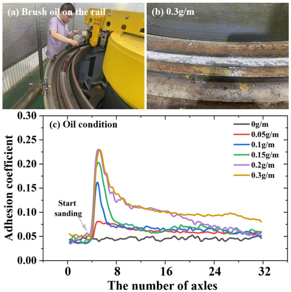
Adhesion enhancement with sanding under oil conditions: (a) brush oil on the rail, (b) 0.3 g/m, and (c) oil condition.

Adhesion enhancement with sanding under oil/iron filings mixture conditions: (a) track surface, (b) 0.3 g/m, and (c) oil and iron filings mixture.
The experimental results under oil conditions indicate that due to the degradation of the sanding effect, a single application of sanding cannot maintain high adhesion across all axles of the entire train.
Oil and iron filings mixture condition
Oil on the rail surface often combines with iron filings, dust, and other solid microparticles to form low-adhesion contaminants similar to grease, 2 significantly compromising the adhesion coefficient. Therefore, this study conducted sanding adhesion enhancement tests under conditions of oil/iron filings mixtures. Without sanding, the adhesion coefficient under the oil and iron filings mixture was as low as approximately 0.03, which is even more unfavorable than under oil contamination alone. When the sanding rate was 0.05 g/m, the adhesion coefficient suddenly increased to 0.12 but quickly decreased again, with the high-adhesion state lasting for only 4–5 axles. Subsequently, the adhesion level rapidly dropped back to around 0.03. As the sanding rate increased, the adhesion improvement became more significant. Sanding rates of 0.1, 0.15, 0.2, and 0.3 g/m corresponded to maximum adhesion coefficients of approximately 0.14, 0.15, 0.19, and 0.23, respectively. The presence of the oil and iron filings mixture results in even lower adhesion, likely due to the fine iron filings mixing with the oil, increasing the viscosity of the mixture and potentially acting as a solid lubricant.
The tests above showed that the combination of oil and iron filings results in even lower adhesion than oil contamination alone. However, sanding significantly improves adhesion, although the adhesion enhancement diminishes after multiple axles pass.
Sanding deterioration performance
Sections “Water condition,”“Oil condition,” and “Oil and iron filings mixture condition” demonstrate that the effect of sanding deteriorates with the increasing number of wheel passes. The adhesion coefficient increment, sanding rate, and number of passing axles under three different contamination conditions (water, oil, and oil/iron filings mixture) were organized into a three-dimensional graph, as shown in Figure 6, following the methodology used in the Knorr test report. 21 It can be observed that the adhesion coefficient increment increases with the sanding rate in all three conditions, and the enhancement effect gradually reaches saturation. As the test axles move further from the sanding position, the adhesion increment decreases, with the degradation of adhesion being more pronounced under oil conditions.
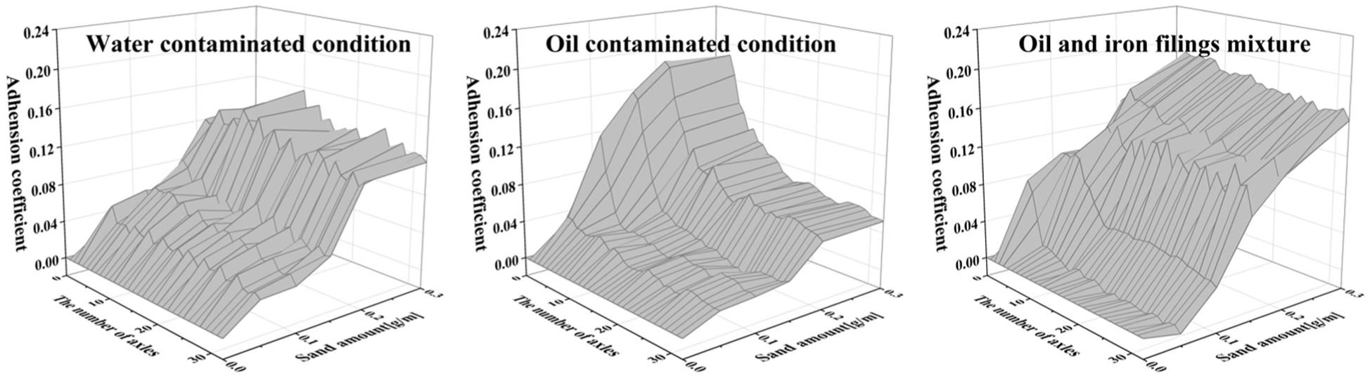
Adhesion enhancement effect after sanding.
Under water conditions, the adhesion coefficient remains above 0.15, which exceeds the required value for emergency braking deceleration (approximately 0.1
Adhesion enhancement effects at different sanding rates.

Sanding optimization based on deterioration performance
The purpose of sanding under low adhesion conditions is to support train braking and ensure safe stopping. Therefore, this section will discuss the braking performance of subway vehicles before and after the installation of sanding devices.
Braking and anti-slip simulation platform with sanding degradation
To simulate the braking performance of subway vehicles under low adhesion and sanding conditions, a subway braking/anti-slip simulation platform was constructed. As shown in Figure 7, the topology of the simulation platform includes models for the train, pneumatic valves, electronic braking control unit (EBCU), and wheel-rail adhesion. The platform allows different levels of braking force to be applied to the train via the interface, enabling the simulation of braking/anti-slip performance. The constructed subway braking and anti-slip simulation platform meets the performance requirements specified in the EN15595 standard. 28 This includes key performance indicators such as braking distance, braking time, axle speed, and slip depth under various rail surface conditions, including dry and low-adhesion scenarios. As such, the platform can partially serve as a substitute for field testing.

Topology diagram of the simulation platform.
Electronic braking control unit
The Electronic Braking Control Unit (EBCU) serves as the central controller for braking in subway vehicles. It processes braking commands, calculates the required braking force based on inputs such as train speed, axle load, and controls the corresponding pneumatic components to achieve the target brake cylinder pressure, as depicted in Figure 8. This study focuses primarily on braking performance and sand application for adhesion enhancement during emergency braking, and thus, the EBCU is responsible only for the distribution of air braking force, excluding electric braking.

Control logic of the braking system.
Train model
To investigate the braking performance of the subway, a train model is required. In the absence of curve effects and with minimal coupling between the longitudinal and lateral degrees of freedom, 29 this study focuses on the braking performance under low adhesion and sanding conditions. A longitudinal dynamic model for an 8-vehicle train was developed using Simulink, as illustrated in Figure 9.

Diagram of the train model: (a) topology diagram of subway and (b) single vehicle model.
The complete train model is composed of eight individual vehicles. Each vehicle model includes the wheelsets, bogies, vehicle body, primary suspension, and secondary suspension. Each vehicle is equipped with two bogies and four wheelsets, with vehicles connected by coupler forces. The wheel motion consists of both rotation and longitudinal translation. The dynamic equations for wheel rotation and longitudinal translation are given by equations (3) and (4), respectively.


In this model,
Model of the pneumatic braking unit
This study focuses on simulation experiments for subway vehicles, constructing a model of the EP2002 pneumatic braking unit to simulate the actions of various pneumatic components during train braking and anti-slip operations. Due to the complexity of the pneumatic components, which makes analytical solutions difficult, the AmeSim software was used to model and analyze the braking system’s pneumatic circuit. The constructed model, as shown in Figure 10, includes the main regulator, secondary regulator, load unit, EP valve, BCP regulation module, remote relief valve, and link valve. A comparison between the simulated and real EP2002 systems is shown in Figure 10. The simulation results closely match the experimental data, confirming the validity of the model.

Pneumatic circuit of the EP2002 braking system: (a) EP2002, (b) service braking, and (c) emergency braking.
Anti-slip system
During train braking, when the adhesion coefficient between the wheels and rails becomes low, wheel sliding may occur. To prevent wheel lock-up, the braking system incorporates an anti-slip control mechanism. Without such a system, excessive braking force would immediately exceed the available adhesion, leading to rapid wheel lock-up and loss of effective braking. Therefore, the wheel slide protection (WSP) system is a critical component of the braking model, especially under low-adhesion conditions. The WSP system, commonly used in modern rail vehicles, is functionally analogous to the anti-lock braking system (ABS) found in automobiles. Its core purpose is to detect the onset of wheel slide and modulate the brake force in real time, thereby maximizing adhesion while preventing the complete loss of friction caused by locked wheels. The operational principle of the anti-slip system is illustrated in Figure 11(a). When the braking force exceeds the available adhesion force, the wheel speed drops rapidly, leading to a discrepancy between the wheel speed and the vehicle speed. This condition is identified as Point A in the anti-slip control logic. To prevent excessive wheel-rail speed differences that may result in wheel lock-up, the Electronic Brake Control Unit (EBCU) activates the anti-slip valve to either release or hold the brake cylinder pressure once the speed difference or deceleration of the sliding axle surpasses a predefined threshold, denoted as Point B. As the sliding diminishes and the speed difference returns below a specified threshold, the EBCU determines that adhesion has been recovered and re-applies the braking force, this point is marked as Point C. The anti-slip control process relies on commonly used criteria, such as speed difference, deceleration, slip ratio, and the rate of change of deceleration. Regardless of the specific criterion selected, the control follows a structured threshold sequence corresponding to Points A, B, and C. To represent this logic in the simulation, a WSP control module was implemented using Stateflow in Simulink. This enables dynamic switching among the brake cylinder’s charging, holding, and releasing states in response to varying adhesion conditions. The specific control criteria adopted in this study are illustrated in Figure 11(b).
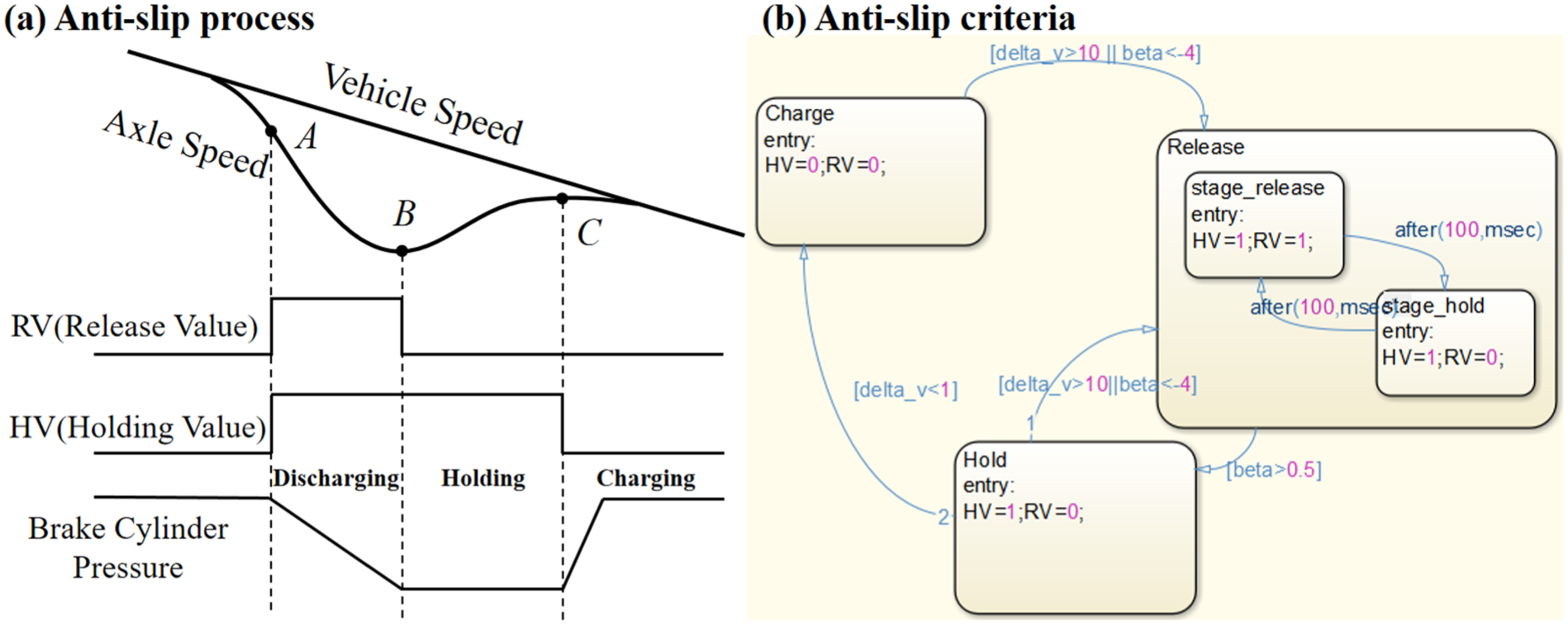
Anti-slip control logic: (a) anti-slip process and (b) anti-slip criteria.
Wheel-rail adhesion model with sand deterioration
This paper presents a wheel-rail adhesion model considering the deterioration due to sanding, based on the Polach model. The friction boundaries for the adhesion model at different axle positions are derived from the experimental results in Section “Sanding deterioration performance.” The Polach model is a nonlinear wheel-rail adhesion calculation method that can fit the adhesion coefficient characteristics under various rail conditions by adjusting relevant parameters. 30 It is widely used in train anti-slip simulations. The adhesion model, constructed using the Polach model under a sand application rate of 0.2 g/m with oil is shown in Figure 12. By adjusting the model parameters for the front and rear axles, the variation in axle adhesion can be simulated. Similarly, adhesion models for conditions involving water and oil/iron filings mixtures are constructed in the same manner, providing input for the subway braking/anti-slip simulation platform.

Inter axis adhesion changes fitted by the Poalch model.
Braking performance analysis with sand deterioration
Braking performance
To explore the necessity and installation location of sanding devices on subway, a study on the anti-slip performance of the subway vehicles under low adhesion and sanding conditions was conducted. First, simulations were performed for the rail surfaces with water, oil, and oil/iron filings mixtures under non-sand application conditions.
Under water conditions, the adhesion coefficient is relatively high, ensuring adequate adhesion across all axles. The vehicle speed matches the axle speed perfectly, with no wheel sliding occurring. As shown in Figure 13, the deceleration and brake cylinder pressure curves over time indicate that both the deceleration and brake cylinder pressure reach their target values. For a train with an initial speed of 100 km/h and a load of AW0, the braking time is 26.78 s, and the braking distance is 381.7 m.

Braking performance under water conditions.
Under oil-contaminated conditions, the wheel-rail adhesion coefficient is low, with values consistently around 0.04 across all axles, resulting in wheel sliding. Figure 14(a) presents the time-varying curves of speed, deceleration, brake cylinder pressure, and overall vehicle deceleration for the first axle of the leading vehicle. Due to the reduced adhesion, the anti-slip valve is activated, and the brake cylinder continuously cycles between charging and releasing to prevent wheel lock-up. However, this significantly diminishes braking performance. The average deceleration is approximately 0.032, which is well below the target deceleration. The braking time is 73.04 s, and the braking distance is 1037.1 m. Similarly, under oil/iron filings mixture conditions, the adhesion of the rear axle does not show a significant improvement compared to the front axle, and the adhesion coefficient is even lower. Figure 14(b) shows the simulation results for the first axle of the leading vehicle under the oil/iron filings mixture condition. As indicated, the braking time increases to 90.61 s, with a braking distance of 1285.0 m.

Braking performance under low adhesion conditions: (a) oil and iron filings mixture and (b) oil contaminated condition.
After the sanding is applied to the first axle of the leading car, the adhesion coefficient for each axle varies as described in Section “Sanding deterioration performance.” As shown in Figure 15, when the sanding rate is 0.2 g/m under oil-contaminated conditions, the operational status of the first axle of each vehicle is presented. It can be observed that after sanding is applied, the increased adhesion prevents wheel sliding on the first four vehicles. However, the subsequent vehicles continue to experience wheel sliding due to the diminishing sanding effect. Simulations were conducted to study the braking performance of the train under different sanding rates, specifically under oil and oil/iron filings mixture conditions, as shown in Table 4. It is evident that the effect of sanding is significant. Even with the smallest sanding rate of 0.05 g/m under oil conditions, the impact on overall braking performance is substantial. Although all axles still experience slip after sanding, the braking distance is reduced from 1037.1 to 727.8 m. Furthermore, when the sanding rate increases to 0.3 g/m, nearly no axle experiences slip.

Wheel sliding of the first axle of each vehicle.
Braking performance under different sanding rates.

Recommendations for installing sanding devices on subways
This study shows that for subway trains, anti-slip control alone may not provide effective braking under some low-adhesion conditions. Sanding is important for improving adhesion between wheels and rails, especially when the rail surface is contaminated with oil or mixtures of oil and iron filings. However, the positive effect of sanding decreases over time in these situations. Therefore, the most effective approach is to install a sanding device in front of the first axle of the leading vehicle. When a single sanding device is operating, even under the most severe oily contamination conditions, it can meet the emergency braking adhesion requirements for more than 13 axles of the train. Therefore, increasing the number of sanding devices greatly helps suppress wheel slip and reduce braking distance. Given the complex and changing operating environments faced by subway trains, it is recommended to install sanding devices in front of the first axle on both the leading and trailing vehicles to ensure reliable and consistent braking performance.
Conclusions
This study investigates the effects of sanding on adhesion enhancement and degradation under conditions of water, oil, and oil/iron filings using a circumferential wheel-rail test rig. The inclusion of water condition serves primarily to provide completeness and a basis for comparison, as sanding is generally unnecessary under pure water conditions. Conversely, sanding is demonstrated to be essential in mitigating adhesion loss under oil and oil/iron filings contamination. Further analysis was conducted on the impact of sanding on train braking performance, leading to recommendations for the optimal installation of sanding devices on subway trains. The key findings are as follows:
(1) Sanding effectively improves adhesion under conditions involving water, oil, and oil/iron filings. However, increasing the amount of sand does not always lead to better adhesion; there is a limit to the benefits it can provide.
(2) The effectiveness of sanding decreases as the number of rolling axles increases, particularly in oil-contaminated conditions. For subway trains, this means that fewer axles maintain high adhesion after a single sanding when oil is present.
(3) A subway braking and anti-slip simulation platform, accounting for sanding degradation, was developed for water, oil, and oil/iron filings conditions. Simulations demonstrated that, even with a single sanding device installed in the direction of train movement, a small amount of sanding can significantly reduce wheel slip under low-adhesion conditions. Increasing the sanding quantity can potentially eliminate wheel slip entirely, greatly enhancing braking performance.
(4) It is recommended that subway vehicles be equipped with sanding devices in front of the first axle at both the front and rear of the train to address braking challenges in extreme low-adhesion scenarios.
Footnotes
Handling Editor: Sharmili Pandian
Funding
The authors disclosed receipt of the following financial support for the research, authorship, and/or publication of this article: This work was supported by the National Natural Science Foundation of China [grant numbers 52505122]; CRRC Academy [grant numbers 2022CYY005]; Changzhou Sci & Tech Program [grant numbers CJ20241089].
Declaration of conflicting interests
The authors declared no potential conflicts of interest with respect to the research, authorship, and/or publication of this article.