
Abstract
Splitter-blade impellers are increasingly being adopted in centrifugal pumps due to their superior performance. However, their service life is significantly reduced when handling fluids containing even small amounts of sediment. To investigate the wear characteristics of splitter-blade centrifugal pumps under solid-liquid two-phase flow conditions, a combined approach of numerical simulation and experimental study was employed to analyze wall wear under low solid-phase particle concentrations. The results demonstrate that the numerical simulations meet the required accuracy for analysis, with maximum relative errors of 4.8% for head and 3.4% for efficiency. The head curve of the centrifugal pump equipped with splitter blades is generally higher than that of the pump without splitter blades under both single-phase and solid-liquid two-phase flow conditions. Notably, under low-flow-rate conditions in the solid-liquid two-phase flow, the impeller with splitter blades demonstrates better head stability. Although the introduction of splitter blades alters the flow field structure at the impeller inlet to some extent, it also enhances the uniformity of pressure and velocity distribution in the circumferential direction at the impeller outlet. The presence of splitter blades primarily affects the wear characteristics on the pressure side of the blades and the middle and rear regions of the impeller rear shroud, resulting in reduced wear. However, as the solid particle concentration increases, impeller wear becomes more severe, suggesting that this type of centrifugal pump should be avoided in high-concentration conditions. Therefore, impellers with splitter blades exhibit certain advantages in transporting fluids with low solid-phase concentrations. This study provides important theoretical insights and data support for the hydraulic optimization of centrifugal pump structures.
Keywords
Introduction
In modern industrial processes, centrifugal pumps, as efficient fluid transport equipment, are widely used across various sectors such as subsea mining, seawater transportation, chemical engineering, and power generation.1–4 Their basic working principle involves accelerating the fluid through a rapidly rotating impeller to generate a pressure difference, thereby delivering the fluid to the desired location. The performance and operational state of centrifugal pumps directly impact the efficiency and cost of industrial production. 5 As industrial operations continue expanding and automation advances, the performance requirements for centrifugal pumps have become increasingly stringent. In recent years, with continuous technological advancements, centrifugal pump design has evolved, leading to the development of the splitter blade concept.6–8 A splitter blade is an auxiliary blade added downstream of the main blade within the flow passage of the impeller. By altering the fluid flow path along the blades, it optimizes the flow pattern and reduces hydraulic losses, thereby improving the overall performance and stability of the pump.9–11
Numerous researchers have found that centrifugal pumps equipped with splitter blades outperform conventionally designed pumps in both internal flow patterns and external characteristics. Gad et al., 12 using entropy generation theory, investigated the energy loss in a centrifugal pump with splitter blades. They found that the impeller region contributed approximately 70% of the total flow loss, while the energy loss in the splitter blade region accounted for only 15.3% of the total, indicating lower energy dissipation. Ke et al. 13 applied an artificial fish swarm algorithm to optimize the geometric parameters of splitter blades, resulting in an optimal blade structure. Their results showed that the splitter blades effectively mitigated flow recirculation, suppressed trailing vortex formation, and alleviated cavitation at the leading edge of the main blade. Kang et al. 14 studied the cavitation characteristics during the startup process of a centrifugal pump with splitter blades and found that splitter blades could enhance the pump’s anti-cavitation performance. Yuan and Yuan 15 reported that adding splitter blades increased the pump head by approximately 10 m and improved efficiency by nearly 4%. Additionally, the wake flow structure at the impeller outlet was significantly improved, with reduced flow separation in the blade passages.
In practical applications, centrifugal pumps are often required to handle not only single-phase flows but also solid-liquid two-phase flows, adding complexity to their operating environment. 16 Solid particles can not only alter the physical properties of the fluid but also change the entire flow structure, and have a significant impact on the internal components of the pump—most notably in the form of wear. 17 Wear not only reduces pump efficiency but may also lead to equipment failure and downtime. In severe cases, it can cause operational instability, increased energy consumption, and even physical damage to the pump. Therefore, minimizing internal wall wear, and thereby enhancing the service life and operational efficiency of centrifugal pumps, has become a key focus in both research and engineering practice.
In recent decades, researchers have investigated the wear characteristics inside centrifugal pumps through both experimental studies and numerical simulations. On the experimental side, Aiming et al. 18 conducted wear tests on impellers transporting solid-liquid two-phase flows. After 3000 h of operation, they measured the total weight loss of the impeller and the reduction in blade thickness. Gandhi et al. 19 analyzed the wear after 2 h of testing and found that the volute exhibited less wear when the pump operated near its best efficiency point (BEP) compared to lower flow conditions, indicating a longer service life at optimal flow rates. Li et al. 20 tested impeller wear using sand particles with a diameter of 0.1 mm and observed that as the particle volume fraction increased, surface wear became significantly more severe. However, due to the high time and cost requirements of wear testing, experimental studies on centrifugal pump wear under solid-liquid two-phase flow conditions remain relatively limited. With the advancement of computational fluid dynamics (CFD), numerical simulation has become the most cost-effective method for predicting wear characteristics on pump walls. Pagalthivarthi et al. 21 utilized the Discrete Phase Model (DPM) combined with the standard k-ε turbulence model to analyze internal wear in centrifugal pumps under various operating and geometric conditions. Noon and Kim 22 used three-dimensional numerical simulations to study the wear behavior of centrifugal pumps transporting lime slurry. Their findings showed that wear increased with higher particle impact velocity, concentration, and size, while the pump head and efficiency decreased with increasing particle volume fraction. Xiao et al. 23 proposed a numerical framework to evaluate erosion-induced wear in centrifugal pumps caused by slurry flow. By tracking particles in a Lagrangian reference frame, they were able to predict wear patterns. Their results revealed that after prolonged operation, erosion rates at the impeller outlet edge and near the blade base decreased significantly. However, impeller wear enhanced recirculation, expanding the maximum wear zones at both the suction and pressure sides of the blade tips, which increased the area affected by particle motion. Mendi and Lei 24 adopted the Eulerian-Lagrangian approach to study particle-induced wall wear in centrifugal pumps. The study found that wear rate increased as a power function of particle concentration and was proportional to the number of particle impacts. The primary wear mechanisms were impact and sliding friction between particles and blades. Huang et al. 25 selected an IS-type centrifugal pump to analyze the motion trajectories of low-concentration quartz sand particles based on the DPM model, and evaluated the wear rate on pump walls. The average wear rate inside the pump increased with particle volume fraction. In a follow-up study, 26 they applied a coupled DEM-CFD method with the Archard wear model to analyze wear on flow-passing components under three different flow rate conditions. The results indicated that the volute accounted for a significant portion of the total wear in the pump. Zhao and Zhao 27 used the DPM model to assess wear on flow-passing components during sand-water transport. Peng et al. 28 investigated the influence of the presence or absence of back vanes on internal wear distribution. Tarodiya and Gandhi 29 performed 3D unsteady flow simulations using a DPM-based model to examine the two-phase flow and wear patterns inside centrifugal pumps. They quantified the wear at various volute locations under different operating and solid-phase conditions and found that lower flow rates and pump speeds helped reduce wear. Lai et al. 30 employed a Lagrangian particle tracking method along with the E/CRC wear model to predict wear on pump walls caused by sediment-laden river water. Their results showed that the highest wear rates occurred on the blades and the rear shroud.
However, the aforementioned studies are primarily based on conventional centrifugal pump impellers, with limited discussion on the internal solid-liquid two-phase flow characteristics in pumps equipped with splitter blades. Sadd et al. 31 investigated the impact of splitter blades on the performance of two-phase flow centrifugal pumps. Their results showed that, compared to the original impeller, the net head of the pump at the design point increased by 11.8%, and pressure fluctuations throughout the impeller were significantly reduced. Abdolahnejad et al. 32 found that splitter blades caused the best efficiency point (BEP) of the solid-liquid two-phase pump to shift toward lower flow rates, and the pump head increased from 29.7 to 31.7 m. However, these studies did not consider the wear effects of solid particles on the splitter blades within the pump.
At present, the specific mechanisms by which splitter blades influence internal wall wear characteristics remain unclear. In practical industrial applications, splitter blades are the critical components of centrifugal pumps, not only determine the fluid flow behavior but also directly affect wall wear patterns. Therefore, an in-depth investigation into the influence of splitter blades on wall wear characteristics is essential. Such research can aid in optimizing pump design and operating parameters, while also providing theoretical support for improving equipment efficiency and extending service life.
This study aims to explore the effects of splitter blade design and operating conditions on wall wear characteristics inside centrifugal pumps. Combining fluid dynamics theory with experimental methods, it examines the wear behavior influenced by splitter blades under solid-liquid two-phase flow conditions. The research mainly focuses on the following aspects: first, physical models of centrifugal pumps with and without splitter blades are established; second, based on CFD simulations and experimental validation, the external energy performance of the pumps under solid-liquid conditions is compared; finally, the wear behavior of key flow-passing components is analyzed, and by comparing the internal flow structures in different regions, the primary factors contributing to wear at critical regions are identified. The findings of this study are expected to provide theoretical guidance and technical support for the optimization and practical application of centrifugal pumps.
Physical model method
Research model of pump
This study selects the ISG25-220 single-stage horizontal centrifugal pump as the primary research subject. The core hydraulic structure of the pump is depicted in Figure 1. The flow-passage components were hydraulically designed using the velocity coefficient approach derived from one-dimensional flow theory, with the corresponding design specifications summarized in Table 1. The specific speed of the impeller is determined using equation (1). The working medium in the simulation consists of a water–concrete particle mixture. To meet performance requirements, the blade outlet width was increased by 0.5 mm through geometric stretching, and a similar adjustment was made to the model length within the numerical domain.

Schematic diagram of main hydraulic structure of pump.
Main parameters of the centrifugal pump model.

The design method for splitter blade profiles is generally the same as that used for conventional blades. However, during the profile design process, it is essential to determine the inlet diameter of the splitter blade, which defines its length. This parameter has a direct impact on impeller performance: if the splitter blade is too long, it may cause blockage at the impeller inlet; if it is too short, it may fail to effectively modify the jet-wake structure at the impeller outlet, thereby reducing pump efficiency. Therefore, careful consideration must be given when selecting the inlet diameter of the splitter blade. The inlet diameter is calculated using equation (2). In this study, the final selected inlet diameter of the splitter blade is 118 mm. A comparison of impellers with and without splitter blades is shown in Figure 2. Impeller #A represents the original impeller and the Impeller #B represents the splitter impeller.

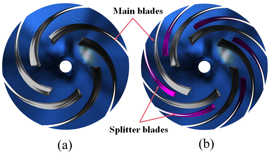
Splitter blades structure: (a) Impeller #A and (b) Impeller #B.
Pre-processing of CFD methodology
Prior to initiating the numerical simulation of the centrifugal pump, several preparatory steps are necessary. The first involves establishing the computational domain using three-dimensional modeling software. In this work, the 3D geometry of the pump’s flow domain is constructed with PRO/E, and the domain is subdivided into regions including the inlet, impeller, clearance, volute, and outlet sections. To enhance simulation accuracy, each section is appropriately extended where required. A visual representation of the computational domain configuration is provided in Figure 3.

Computational domain geometry of the pump model.
Grid is the carrier of simulation and analysis, and the quality of grid has an important impact on the calculation accuracy and efficiency. 33 In this paper, ANSYS ICEM is used to divide the hexahedral structure of the whole basin. In the process of discretization of the calculation domain, the mixed mesh method is adopted, with hexahedral structured mesh used for the inlet domain, outlet domain, volute and pump cavity, which can not only accurately control the streamline distribution and the orthogonal direction of the boundary layer, but also flexibly adjust the distance between nodes to adjust the density of the boundary layer mesh. 34 As for the impeller, due to its complex hydraulic geometry, the generated hexahedral mesh quality is poor, so the tetrahedral unstructured mesh is used to generate. For the three impeller schemes that need to be compared in this paper, the same mesh generation standard is adopted, and the final mesh quality is higher than 0.5. Figure 4 shows the meshing scheme and refinement for different computing domains.

Mesh details of different simulation domains.
Mesh refinement in the boundary layer region allows for more accurate capture of near-wall flow behavior and reflect the flow characteristics in the near-wall region. 35 Therefore, it is necessary to refine the boundary layer of blade surface and volute tongue to ensure the calculation accuracy. In order to meet the requirements of different flow patterns on the number of grids in the near wall area, in order to ensure that there are enough nodes in the area, y+ value can be used to test the location of the node closest to the wall. y+ value represents the distance from the node closest to the wall, and is a dimensionless variable, whose definition is as follows 36

Where, u represents the wall friction velocity, m/s; y represents the distance from the first node to the wall, m; v represents kinematic viscosity, Pa s. The y+ values of blade surface and volute wall are shown in Figure 5.

Distribution of y+ on the blade.
Grid independence test
To ensure the reliability of the numerical simulation, 37 a grid independence analysis is essential to minimize errors associated with mesh resolution. In this study, multiple grid densities are employed to discretize the computational domain. The analysis is conducted by examining the variation in pump head under design conditions as the number of grid elements changes. Based on the results, an optimal mesh configuration is determined for subsequent simulations.
To evaluate the sensitivity of the computational mesh, this study adopts the grid convergence index (GCI), a method initially introduced by Roache. 38 The GCI approach necessitates that the obtained results adhere to the condition of monotonic convergence to ensure reliability. In this work, three distinct grids with varying levels of refinement were constructed and analyzed under the rated operating conditions of the original impeller design. This process enables a systematic assessment of how mesh resolution influences the accuracy and stability of the simulation results. The formula for calculating GCI is as follow 39


Where Fs is the safety factor, taking values in the range 1.25–3.00, and 1.25 when three or more grids are used. r is the grid refinement ratio. N is the number of control cells of the grid; D is the computational dimension; the subscript b represents different grid schemes, with larger b indicating a denser grid. φ is the relative error between the numerical results obtained from two successively refined grids. fb is the numerical discrete solution of the selected convergence parameter.
κ is the order of convergence. When three sets of grids are used for GCI analysis, κ can be calculated iteratively based on equations (7)–(9) as follows:


Where g(κ) is the κ-order error term coefficient that does not vary with the grid. It should be noted that when
As can be seen from the Table 2, with the increase of the number of grids, the value of GCI decreases from 1.48% to 0.62%, meeting the requirement that the value required by the GCI convergence standard is less than 1. Therefore, in the final calculation scheme, the grid density scheme is selected for grid generation in all calculation domains.
Calculated results of GCI with different size of grids.

Fluid control equations
In this paper, the solid phase concentration is small, and the liquid phase inside the centrifugal pump is treated as the incompressible fluid. The continuity equation and momentum equation are shown in equations (10) and (11), respectively, with the momentum exchange source term given in equation (12).


Where u is the fluid velocity (m/s), p is the static pressure (Pa), ρ is the fluid density (kg/m2), and μ is the dynamic viscosity of the fluid (N s/m2).
Most flows in engineering applications are turbulent, and a widely used numerical framework for simulating such flows is based on the Reynolds-Averaged Navier–Stokes (RANS) equations. This approach involves applying Reynolds decomposition to the instantaneous Navier–Stokes equations, separating the flow variables into mean and fluctuating components. In this study, the RNG k-ε model 40 is adopted. Compared to the standard k-ε model, this model can more accurately simulate the flow in the near-wall region 41 and also considers the effects of curvature, making it more precise for simulating phenomena generated by fluid flowing around curved walls. Its expression is as follows:
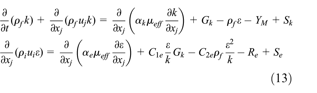
Where k is the turbulent kinetic energy; ε is the dissipation rate; Gk is the turbulent kinetic energy generated by the mean velocity gradient; C1ε = 1.42; C2ε = 1.68; Sk and Sε are source terms.
Control equations of particle motion and collision
The calculation of particle trajectories in the solid discrete phase model is independent, with each particle’s motion being tracked over specific time intervals. 42 In the semi-open impeller centrifugal pump, the change in particle trajectories is primarily influenced by gravity, drag force, virtual mass force, Basset force, Saffman lift, and Magnus lift. Since the continuous phase is water, the Basset force, Saffman lift, and Magnus lift are negligible compared to drag force. 43 In this study, the Euler-Lagrange framework is utilized, the particle diameter is set as 0.5 mm, and the continuous phase is water. Therefore, the analysis focuses only on drag force, gravity, buoyancy, virtual mass force, and pressure gradient force. The governing equation is the generalized form of Newton’s second law, which can be expressed as. 44
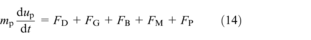

In the formula, mp is the particle mass, kg; up is the particle velocity, m/s; Ip is the particle’s moment of inertia; ωp is the particle’s angular velocity, and Tp is the total torque applied to the particle.
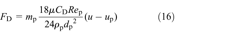

In the formula, CD is the drag coefficient; Rep is the particle Reynolds number; ρp is the particle density; dp is the particle diameter, in mm. The gravity FG and buoyancy FB can be expressed as:

The virtual mass force FM can be expressed as
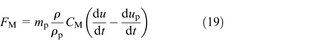
Where CM is the virtual mass coefficient of 0.5. The pressure gradient force FP can be expressed as:

When particles move in the flow field, collisions between particles will occur, generating a contact force Fc. The contact force Fc exerted on a particle can be expressed by the following formula:

Where: Fc,n represents the normal force, Fc,t represents the tangential force. The normal and tangential forces can be calculated by the following formulas:


Where, n represents normal, t represents tangential, d is the compression distance during the collision of two particles, vn and vt are the normal and tangential velocities of the two particles at the contact point, kn and kt represent the normal and tangential stiffness, and Nn and Nt are the normal and tangential damping coefficients. In this study, to accurately simulate collisions between particles and between particles and walls, the Hertz-Mindlin no-slip contact model is used. 45
Wall wear model
Particles collide with and cut the flow surfaces of components, causing deformation and material fatigue failure. The resulting wear is a function that depends on particle characteristics, impact conditions, and the properties of the wall material. Common wear models used by researchers include the Finnie model, DNV model, Oka model, and Ahlert wear model. The DNV and Oka models are based on gas-solid two-phase flow, which differs from the liquid-solid two-phase flow environment in this study. The DNV model does not account for changes in wear mechanisms at different angles, 46 while the Oka model references a benchmark erosion rate under an impact angle of 90°, which is different from the typical inclined angle impact mechanism seen in centrifugal pumps. 47 The Ahlert model is derived from empirical data and extensive experimental fitting, without considering the material removal mechanisms during wear. 48 The Finnie model, on the other hand, is based on particle displacement and cutting mechanisms for material removal and distinguishes wear mechanisms at different impact angles. This makes it particularly suitable for studying the wear mechanisms under the inclined impact angles typical in hydraulic machinery such as centrifugal pumps,28,49 aligning more closely with the conditions of this study. Therefore, in this paper, the Finnie wear model is adopted to investigate the wear behavior of flow-passing components in a centrifugal pump under solid-liquid two-phase flow conditions. The classic wear model proposed by Finnie is as follows 50 :

In the formula, E is a dimensionless parameter for wear; k is a constant used to obtain the dimensionless erosion factor; Vp is the solid-phase particle impact velocity, in m/s; n is the velocity index, which is related to the material properties of the wall surface, with typical values ranging from 2.3 to 2.5 for metallic materials; f(θ) is a dimensionless function of the particle impact angle. 51
Boundary condition setup
To ensure the accuracy of the calculation results, a bidirectional coupled Eulerian-Lagrangian approach is employed in this paper for the numerical simulation of solid-liquid two-phase flow inside a low specific speed centrifugal pump. In this model, the liquid phase (water, with a temperature of 25°C and a density of 997.05 kg/m3) is treated as the continuous phase, while solid particles (assumed to be spherical with a density of 2650 kg/m3) are treated as the discrete phase. The particles are uniformly distributed at the inlet, with an initial velocity matching that of the fluid. In the geometry model, the impeller is set as the rotating domain, and the Multiple Reference Frame (MRF) method is used to apply the rotation effect as an additional source term in the momentum equations. The inlet pipe and diffuser without blades are set as the fixed domain. The wall surface is treated with a no-slip condition. For boundary conditions, in the steady-state simulation, the inlet is defined as a total pressure boundary, and the outlet is set as a mass flow rate boundary. The impeller is modeled with a frozen rotor model in the regions where it contacts the inlet section and volute, with a rotation angle of 360° and a total of 2500 computational steps. For the unsteady-state simulation, the same inlet and outlet boundary conditions are used, but the impeller wall is treated as a transient rotating surface, and the contact surface between the impeller and volute is handled as a transient frozen rotor. The total simulation time is 0.103448 s, with a time step of 1.72414 × 10⁻⁵ s, corresponding to five full rotations of the impeller, with a 3° rotation per step. The pressure–velocity coupling is handled using the SIMPLE algorithm. Second-order upwind schemes are applied for the convection terms, and second-order central difference schemes are used for the diffusion terms and pressure gradient. The time discretization is performed using a second-order implicit scheme. To ensure simulation accuracy, the convergence criteria for the continuity and momentum equations are set to 10−4.
Experimental setup
Experimental equipment
In this study, pump performance testing was conducted at the Zhenjiang Machinery Industry Testing Institute. The structure and process of the testing system were based on previous work, 34 and it can be seen in Figure 6. Before the test, the motor was operated under no-load conditions, and torque calibration was performed at the rated speed (1450 r/min). The motor was then connected to the pump shaft. Various instruments and devices were connected according to the testing standards, and water at room temperature was injected into the test pipeline. The system was started, and the instrument operation was checked, with the pipeline vent valve opened to remove any air in the system. During the test, the pump was installed on a closed test bench. Before starting the pump, the inlet and outlet valves were adjusted to their maximum opening, and the motor speed was adjusted to the rated value using a frequency converter. Flow rate was measured using an electromagnetic flow meter on the outlet pipeline with an accuracy of ±0.5%. The inlet and outlet pressures were obtained via pressure sensors, which had a measurement range of −100 to 100 kPa and an accuracy of ±0.5% of full scale (FS). Torque was measured using a torque sensor installed between the pump and the motor with a measurement error less than ±0.2% FS. All measured signals—including rotational speed, flow rate, pressure, and torque—were transmitted through shielded cables to a multi-channel data acquisition system, where they were digitized and logged for subsequent analysis. The output signals for both torque and speed ranged from 4 to 20 mA.

Schematic diagram of the experiment system.
While maintaining the inlet valve fully open, the outlet valve was gradually adjusted to achieve parameter measurements under different flow conditions. When the relevant parameters in the system analysis software stabilized or fluctuated within a small range, these values were considered valid and recorded. After collecting data for the minimum flow condition, the motor speed was slowly reduced to zero using the frequency converter. Once the system was completely shut down and the water flow in the pipeline had stopped, the outlet valve was reopened to its maximum setting. To minimize random errors and improve the reliability of the test data, each condition was tested three times, and the arithmetic average of the energy characteristic data was taken as the final result. Experimental uncertainty at the best efficiency point has also been conducted, and overall uncertainty analysis for the head is ±0.2 %, which meets the requirement of the test. The accuracy and reliability of the numerical simulation were further verified by comparing the simulated results with the measured head and efficiency under single-phase conditions.
Verification of simulation
The pump Data Acquisition Terminal and processing program can calculate the head of the test pump according to the inlet and outlet pressure of the test pipeline, the shaft power can be calculated according to the torque and speed data measured by the torque and speed measuring instrument, and the efficiency can be calculated according to the head and shaft power. The three expressions are as follows


In the formula, p1 and p2 are respectively pump inlet and outlet pressure, Pa. In this test, v1 and v2 are respectively the average flow velocity of the inlet and outlet of the pump, m/s, which can be calculated from the inner diameter of the inlet and outlet pipeline; M is the measured torque of the pump set, M0 is the no-load torque, N m; n is the speed, r/min; Q is the flow rate, m3/h; H is the head, m; P is the shaft power of the pump, kW.
To verify the accuracy of the numerical simulation method, a comparative analysis of the centrifugal pump’s performance under single-phase conditions was conducted. The numerical results for head and efficiency were compared with the experimental data. As shown in Figure 7, the performance curves of the model pump at different flow conditions indicate that the trends in the numerical simulations align well with the experimental results, demonstrating good consistency in the variations of head and efficiency. At a flow rate of approximately 95 m3/h, the pump’s efficiency reaches its maximum, indicating this is the optimal operating point. As the flow rate decreases, the head curve gradually rises, with a local minimum appearing around 45 m3/h, which corresponds to a stall condition. However, the decrease in head is not significant, indicating that flow losses are not severe. In the low flow range, the head curve remains relatively flat, reflecting the changes in the flow field structure within the pump. From the data compared to experimental results, the maximum relative error of simulated values in head is 4.8%, and the maximum relative error of simulated values in efficiency is 3.4%. In all flow conditions, the error between the numerical results and the experimental values is less than 5%, which meets the accuracy requirements for engineering calculations and further confirms the feasibility and reliability of the numerical simulation method.
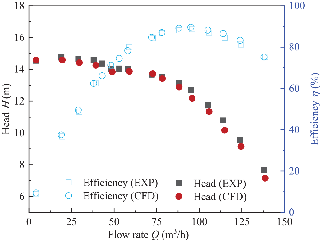
Comparison of simulations and experimental results.
Results and discussion
Comparison of energy performance
In solid-liquid two-phase flow, the addition of solid-phase particles changes the density of the fluid. Therefore, when calculating the pump’s head and efficiency, it is necessary to consider the effect of solid-phase particles on the head. The head calculation formula for solid-liquid two-phase flow is:
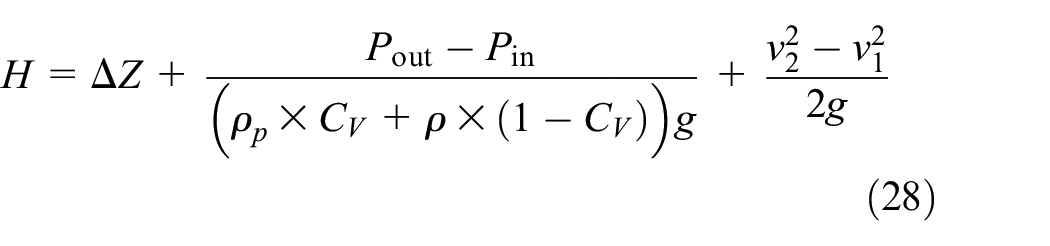
Where H is the head; ΔZ is the position potential difference; Pout is the outlet pressure; Pin is the inlet pressure; v2 is the average velocity at the pump outlet flow section; v1 is the average velocity at the pump inlet flow section; ρp is the solid-phase density; CV is the solid-phase volume fraction.
The pump efficiency calculation formula is:
Where g is the gravitational acceleration; Q is the flow rate.
Figure 8 show the external characteristic curves of the centrifugal pump with and without split-flow blades at different flow conditions, including data for single-phase and for a solid phase concentration of 1%. From the figures, it can be observed that, whether under single-phase or solid-liquid two-phase conditions, the centrifugal pump with split-flow blades exhibits a higher head curve than the pump without split-flow blades in most operating conditions. However, its efficiency curve is slightly lower than that of the original pump without split-flow blades. This is because, although the split-flow blades provide additional power to the fluid within the impeller, they indirectly increase the thickness of the impeller blades, leading to an increase in the blade clearance coefficient, which increases the overall hydraulic losses in the pump and affects the overall hydraulic efficiency. Additionally, an interesting phenomenon is observed: under single-phase conditions, the centrifugal pump with split-flow blades shows a peak in the head curve between 50 and 80 m3/h, while its maximum efficiency shifts to higher flow conditions (∼90 m3/h). This phenomenon is also related to the modification of incidence angles at blade inlet, which will be studied in detail in the next section. In contrast, for the original impeller, the head curve decreases around 50 m3/h, which is markedly different from the pump with split-flow blades. This phenomenon is related to the rotational stall in the centrifugal pump, but as this is not the focus of the current study, it will not be discussed further here. For the solid-liquid two-phase flow conditions, both impeller structures show similar behavior: with the addition of solid-phase particles, the head curve decreases significantly, while the efficiency decreases slightly. The difference is that, for the original impeller, as the flow condition decreases, the head drops more noticeably, especially when the flow condition is below 20 m3/h, where the head decreases by about 18%. For the centrifugal pump with split-flow blades, however, the trend is different: the head initially increases and then decreases, with the most significant drop occurring around 60 m3/h, where the head decreases by about 19% compared to the single-phase condition. Moreover, the head curve is relatively stable in the 30–80 m3/h flow range, differing from the steadily increasing head curve of the original impeller. Overall, under single-phase flow condition, the centrifugal pump equipped with split blades demonstrates a higher head at low flow rates. However, under solid–liquid two-phase flow conditions, its performance does not show a significant improvement compared to the original impeller, and the increase in the number of splitter blades does not lead to a reduction in the efficiency of transporting solid–liquid mixtures. Therefore, centrifugal pumps with splitter blades hold potential for broader application in future engineering scenarios, but it still needs to be further investigated in the next sections.

Comparison of the external characteristic curves of the centrifugal pump with different impeller: (a) Impeller #A and (b) Impeller #B.
Vortex structures of the centrifugal pump with different impeller schemes
To further explore the effects of different impeller structures on the flow characteristics inside the centrifugal pump, the flow field distribution and vortex structure within the main flow components of the centrifugal pump were obtained. Figure 9 shows the vortex structure inside the impeller and the pressure and velocity field distributions at the middle section of the impeller under design conditions for two types of impellers. To identify and analyze vortex structures, the Q-criterion method is applied with a selected threshold value of 34,000 −2. The mid-span cross-sectional plane of the impeller domain is extracted to illustrate the corresponding pressure and velocity fields. Besides, the average pressure and velocity from the impeller inlet to the impeller outlet have been also acquired to better understand the effect of splitter blades, which is shown in Figure 10.
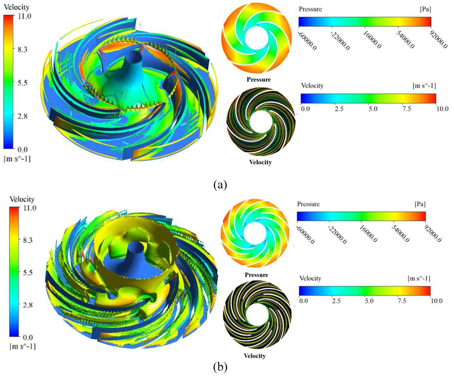
Comparison of internal vortex and flow field distribution ith different impeller structures under design conditions: (a) Impeller #A and (b) Impeller #B.

Comparison of average pressure and velocity along impeller blade under design conditions.
Overall, both impeller structures exhibit relatively stable flow conditions. From the impeller inlet to the impeller outlet, the pressure gradually increases when the streamwise location is about 0.46, and the streamlines do not show sharp bends, indicating smooth transitions in the flow passage. However, there is a slight difference in the distribution of high-pressure zones at the different impeller outlet flow passages. In the flow passage near the impeller shroud, the high-pressure zone at the impeller outlet has a slightly higher pressure than in the other impeller passages. Comparing the two impeller structures, it was found that for the impeller with split-flow blades, the high-pressure zone at the impeller outlet is significantly smaller than that of the original impeller. This is due to the split-flow blades truncating the high-pressure zone within the flow passage. The truncating effect of the split-flow blades improves the consistency of the axial pressure distribution in the outlet passage, making it more uniform compared to the original impeller structure. The high-pressure region near the shroud is also smaller than in the original impeller. The velocity field distribution under different impeller configurations generally follows the same trend as the pressure field distribution. However, in the case of the impeller with splitter blades, an additional peak in velocity is observed near streamwise ≈ 0.7 where is the splitter blade inlet, which differs from the distribution seen in the original impeller. Within the impeller passage, the blades impart kinetic energy to the fluid particles, accelerating the flow and leading to a primary velocity peak at the impeller outlet. The appearance of the secondary velocity peak is therefore attributed to the energy transfer effect induced by the splitter blades.
However, for the original impeller structure, near the volute shroud, the high-speed zone at the impeller outlet is uneven due to the influence of the shroud, resulting in localized speed reduction. In contrast, for the impeller with split-flow blades, the reduction in the outlet flow passage minimizes the effect of the shroud, resulting in a more uniform velocity distribution at the impeller outlet. Another notable difference between the two impeller structures is at the impeller inlet. For the original impeller structure, a very small low-speed region is only present at the suction side near the blade inlet. However, for the impeller with split-flow blades, the introduction of the split-flow blades causes a slight shift in the optimal design conditions, resulting in a small change in the blade inlet angle. The low-speed region near the suction side of the blade becomes significantly larger. This can also be verified in the vortex structure images of the impeller. At design conditions, the original impeller only shows shear vortex structures near the wall, and the vortex influence area near the blade inlet is small. However, for the impeller with split-flow blades, the vortex influence area at the blade inlet suction side is significantly larger. In summary, the inclusion of split-flow blades affects the flow field structure at the impeller inlet to some extent but also improves the pressure and velocity field uniformity in the circumferential direction at the impeller outlet.
Figure 11 shows the vortex structure inside the volute and the flow field distribution near the volute outlet for the centrifugal pump with and without split-flow blades under design conditions. From the figure, it is clear that the impeller structure has a significant impact on the flow state inside the volute. For the original impeller, due to the jet-wake effect at the impeller blade exit, numerous strip-shaped vortex structures appear near the volute’s casing circle and move toward the outer wall of the volute. However, for the impeller with split-flow blades, the strip-shaped vortices still exist but with a much higher intensity compared to the original impeller structure. Additionally, since the split-flow blades also create jet-wake effects at their exit, the vortices between different strips interfere with each other, forming secondary vortices that fill the entire volute region. The root cause of this is that the split-flow blades increase the work done on the fluid inside the impeller flow passage. As the volute needs to convert the fluid’s kinetic energy into potential energy, the fluid inside the volute dissipates more energy through vortices to help expel the fluid toward the outlet. In fact, when the fluid flows near the volute shroud, the flow state for both impeller structures becomes quite similar. This can be observed from the flow fields at the four sections of the volute outlet. For both impeller structures, the velocity distribution and streamline distribution at sections 1 and 2 are almost identical. Although there are slight differences in the streamline distribution at sections 3 and 4, the overall trend shows an increasing level of turbulence. In summary, the split-flow blades significantly affect the flow field structure inside the volute, leading to an increase in vortex structures. The strip-shaped vortices formed by the jet-wake effect also interfere with and affect each other. However, the impact on the flow field near the volute outlet is not as significant.
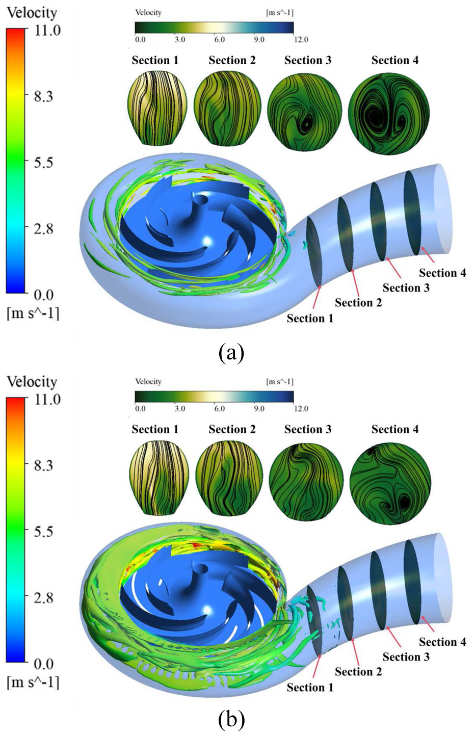
Comparison of vortex and flow field distribution states in the volute with different impeller structures under design conditions: (a) Impeller #A and (b) Impeller #B.
Analysis of wear characteristics inside the centrifugal pump with different impeller schemes
Figure 12 shows the wear characteristics of the impeller wall under design conditions for centrifugal pumps with and without split-flow blades. The particle concentration is set as 200, and the continuous injection position is the pump inlet. From the figure, it can be observed that in both impeller structures, the impeller rear cover plate and blades are subjected to varying degrees of wear, with similar wear regions. For the original impeller structure, the area near the leading edge of the blade pressure surface is most affected by particles, with the wear region concentrated in the middle of the blade inlet. In the middle and rear parts of the blade, while some wear is present, it is less severe. Additionally, the wear in the middle and rear parts of the blade is closer to the root of the blade. On the rear cover plate, the most severe wear is located near the impeller inlet, where particles flow from the inlet pipe into the impeller and first strike the impeller’s inner wall. Then, as particles flow into the impeller passage along with the fluid, they interact with the blade pressure surface and exit the impeller along the pressure surface. Therefore, noticeable particle wear marks can be observed on the side of the rear cover plate near the blade pressure surface. Comparing the impeller structure with split-flow blades, it is found that the severe wear location on the blade pressure surface is almost the same as the original impeller, near the blade inlet. However, in the middle and rear parts of the blade pressure surface, the wear is significantly reduced. This area corresponds to the region of the split-flow blades. From the wear intensity on the split-flow blades, it can be seen that the pressure surface of the split-flow blades takes on the wear load that would otherwise affect the middle and rear parts of the original blades, which reduces the wear in those areas. Moreover, the addition of split-flow blades also reduces the wear on the rear cover plate near the blade pressure surface, with little wear difference observed on both sides of the flow passages of the split-flow blades. Comparing the main blade suction surfaces of both impeller structures, there is no significant difference in wear levels. Therefore, the split-flow blades primarily influence the wear characteristics on the blade pressure surface and the middle and rear parts of the impeller rear cover plate, reducing the wear severity.

Comparison of impeller wall wear characteristics under design conditions: (a) Impeller #A and (b) Impeller #B.
Furthermore, to compare the wear rates of different regions of the impeller under various flow conditions, the area-averaged wear rate on the impeller front cover plate, blade surfaces, and rear cover plate was analyzed, as shown in Figure 13. From the figure, it can be seen that the wear characteristics for both impeller structures are generally similar, with differences primarily in the numerical values. For low flow conditions, the wear rate on the impeller front cover plate is higher, but as the flow increases, the wear rate decreases sharply. Conversely, the wear rate on the impeller rear cover plate follows the opposite trend: at high flow conditions, the wear rate on the rear cover plate is higher, but it gradually decreases as the flow decreases. In addition, for the wear rate on the blades, it initially increases with flow, then decreases, and after that, it starts to increase again. Overall, under different flow conditions, the impeller structure with split-flow blades has a wear rate about 8% higher than the original impeller. This is because the addition of split-flow blades increases the frequency of particle impact on the blade wall surface.

Quantitative analysis of impeller wall wear characteristics under different flow conditions: (a) Impeller #A and (b) Impeller #B.
Figure 14 shows the wear characteristics of the volute wall in the centrifugal pump under the design condition, comparing the impeller with and without split-flow blades. From the figure, it can be seen that for both impeller structures, the most severe wear on the volute wall occurs in the annular volute, while the wear at the volute outlet pipe is not significant. This is mainly because the particles follow the fluid and are ejected from the impeller exit. Although the fluid particles exert drag on the particle points, the particles, due to their larger inertia, still impact the inner wall of the annular volute at a certain angle. After multiple impacts, wear occurs on the wall surface. However, when the particles move through the volute outlet pipe, due to the similarity in flow velocity and direction between the particles and the fluid, the frequency of particle-wall impacts decreases, leading to only minimal friction wear, and thus the wear on the volute outlet pipe wall is not severe.

Comparison of volute wall wear characteristics under design operating conditions: (a) Impeller #A and (b) Impeller #B.
Similar to the analysis of impeller wear, Figure 15 shows the area-averaged wear rate on the volute wall at different flow conditions. It can be seen that the trends in wear rates on the volute wall are similar for both impeller structures at different flow conditions. However, there is a significant difference compared to the average wear rate inside the impeller. At design conditions and lower flow conditions, the wear rate on the volute wall is noticeably higher than at high flow conditions. When the flow decreases to 19 m3/h, the wear rate sharply decreases. In summary, the wear on the volute wall for the centrifugal pump with split-flow blades is slightly higher than that of the original impeller. This is because the split-flow impeller exerts additional work on the particles within the flow path, resulting in slightly higher kinetic energy when the particles exit the impeller. Therefore, when impacting the volute wall, the particles possess higher energy, making it easier for the material to be removed.

Quantitative analysis of volute wall wear characteristics under different flow conditions.
Effect of solid particle concentration on wear characteristics in centrifugal pumps
To further explore the effect of solid particle concentration on the wear characteristics of the inner walls of a centrifugal pump with split-flow blades, the wear characteristics of the impeller and volute walls were compared under four different solid particle concentrations. Figure 16 shows the average wear rate of each part of the impeller of the centrifugal pump with split-flow blades at different solid particle concentrations (Particle Concentration = 200, 500, 800, 2000). From the figure, it can be observed that the wear rate of the wall surface does not follow a linear distribution as the solid phase concentration increases. Specifically, when the solid particle concentration increases from 200 to 500 and from 500 to 800, the average wear rate inside the impeller does not change in the same manner. However, when the solid particle concentration increases from 800 to 2000, the average wear rate inside the impeller rises sharply. Therefore, at low solid particle concentrations, the centrifugal pump with split-flow blades exhibits minimal wear variation, indicating good particle adaptability. However, when the solid phase concentration reaches a certain threshold, the wear rate increases dramatically, leading to fatigue damage to the impeller surface and reducing its service life.

Comparison of average wear rate in different parts of the impeller of centrifugal pump with splitter blades.
Figure 17 shows the average wear rate distribution of the blades along the main flow direction. From the figure, it can be seen that as the solid phase concentration increases, the wear rate on the impeller blades gradually increases, which is consistent with the description in the previous section. By comparing the wear characteristics of the blades at different solid phase concentrations, it is evident that along the main flow direction, from the blade inlet to the blade outlet, the average wear rate shows a certain pulsating characteristic. However, it can be observed from all four concentrations that the inclusion of split-flow blades causes a noticeable decrease in the wear rate in the middle and rear parts of the blades, further validating the previous conclusion with quantitative data. In summary, the impeller with split-flow blades shows excellent particle adaptability at low concentrations. However, as the solid phase concentration increases, the wear on the impeller increases, and it is advisable to avoid operating this type of centrifugal pump at high solid phase concentrations.

Comparison of average wear rate along the main flow direction of the impeller blades in centrifugal pump with splitter blades: (a) particle concentration = 200, (b) particle concentration = 500, (c) particle concentration = 800, and (d) particle concentration = 2000.
Figure 18 shows the wear rate distribution on the volute inner wall of a centrifugal pump with split-flow blades at different solid particle concentrations. Figure 19 provides a quantitative comparison of the average wear rates. From the figure, it can be observed that the wear rate on the volute wall follows the same trend as the solid particle concentration, increasing with the concentration. However, the rate of increase in the average wear rate of the volute inner wall is not a linear relationship with concentration, similar to the wear behavior observed in the impeller. At high solid phase concentrations, the wear rate on the volute inner wall rises sharply, indicating that high solid particle concentrations also have a significant damaging effect on the volute.

Comparison of wall wear rate of the volute in centrifugal pump with splitter blades: (a) particle concentration = 200, (b) impeller particle concentration = 500, (c) particle concentration = 800, and (d) impeller particle concentration = 2000.

Quantitative comparison of the average wall wear rate of the volute in centrifugal pump with splitter blades.
To further analyze the wear characteristics of the volute in different local regions, monitoring lines at different positions in the annular volute were set up (as shown in Figure 20), and the average wear rate data along these lines were collected (as shown in Figure 21). Additionally, the average wear rates across different monitoring lines were quantified and summarized in Table 3. From the figures and table, it can be observed that as the solid particle concentration increases, the wear rate on the inner wall of the annular volute gradually increases. However, comparing the four different solid particle concentrations, the location of the highest wear rate in the annular volute is not the same at different positions. At low solid phase concentrations, the area of most severe wear on the volute wall is near the volute outlet pipe. As the concentration increases, the most severe wear region shifts to the lower part of the annular volute, near Polyline 5. With further increase in concentration, the most severe wear region moves toward the isolation tongue, near Polyline 2. However, when the concentration increases to a certain level, the most severe wear region shifts back to Polyline 5. The main reason for this is that at low concentrations, the impeller’s jet-impeller tail effect causes particles to impact the volute wall, with the strongest jet-impeller tail effect near the volute outlet pipe. As the concentration increases and the number of particles increases, the jet-impeller tail effect weakens, and the wear area gradually rotates counterclockwise toward the isolation tongue. When the concentration reaches a certain level, the interaction between the jet-impeller tail and the particles reaches equilibrium, resulting in the wear location being located at the lower part of the annular volute. In conclusion, the solid particle concentration is positively correlated with the wear degree on the volute inner wall, but not in a linear fashion. The concentration influences the distribution of the severely worn regions on the volute inner wall, but ultimately, the most severely worn region stabilizes in the lower part of the volute.

Schematic diagram of the positions of different monitoring lines in the annular volute chamber.

Quantitative comparison of average wear rates at different monitoring line locations: (a) particle concentration = 200, (b) particle concentration = 500, (c) particle concentration = 800, and (d) particle concentration = 2000.
Comparison of arithmetic mean values of average wear rates at different monitoring line locations.

Analysis of transient wear characteristics in a centrifugal pump with splitter blades
To further explore the wear characteristics of the centrifugal pump with a split-flow impeller under unsteady operating conditions, the area-averaged wear rate in the main regions of the pump was tracked over time at the design operating condition under particle concentration of 200, as shown in the Figure 22. Since previous studies showed that the wear on the impeller front cover plate under design conditions is relatively small, this part is not analyzed here. From the figure, it can be observed that because the impeller blades are the main components that perform work, they are constantly exchanging kinetic energy with the solid-phase particles. Therefore, the fluctuation amplitude of the average wear rate over time is higher. Although the impeller rear cover plate is also one of the more severely worn parts inside the pump, its fluctuation range is smaller, indicating that the number of particles impacting the impeller rear cover plate at different times does not vary significantly. The trend of wall wear in the volute as a function of time shows that, in the initial phase, when the particles have not yet entered the volute, both the wear rate and the fluctuation amplitude are low. However, as the particles stabilize and flow through the volute passage, the fluctuation amplitude of wall wear increases. Compared to the impeller blades and impeller rear cover plate, this fluctuation amplitude is significantly smaller. In conclusion, under unsteady conditions, the transient wear fluctuation amplitude is highest on the impeller blades, followed by the impeller rear cover plate, and weakest on the inner wall of the volute.
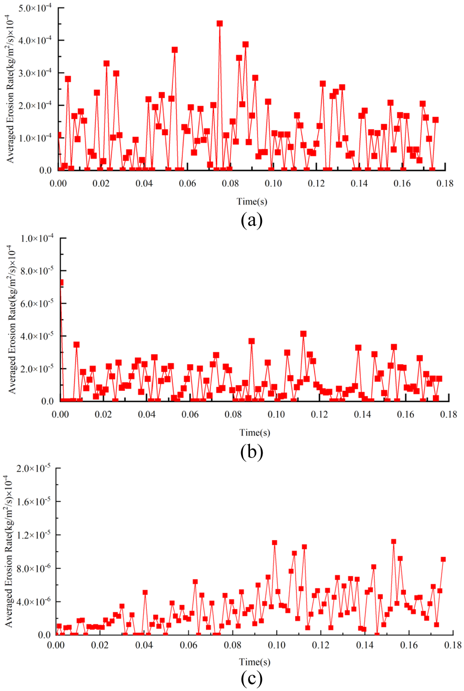
Comparison of transient wear characteristics in different regions of a centrifugal pump with splitter blades: (a) impeller blades, (b) impeller hub, and (c) volute.
Conclusions
This study investigated the effect of splitter blades on the hydraulic performance and internal wall wear characteristics of a centrifugal pump under low solid-phase concentration conditions, using CFD simulations and experimental measurements. Based on the analysis, the following conclusions can be drawn:
(1) Compared with the conventional impeller, the split-flow impeller exhibits a consistently higher head across most operating points. Although the presence of solid particles leads to a general decline in head for both impeller types, a slight improvement in efficiency is observed. Notably, the split-flow impeller maintains better head stability in the low-flow regime, and under two-phase flow conditions, its head remains nearly equivalent to the single-phase scenario, demonstrating improved adaptability in transporting low-concentration solid-liquid mixtures. This validates the design strategy of employing splitter blades to optimize performance in dilute particle-laden environments.
(2) The addition of split-flow blades will affect the flow field structure at the impeller inlet to a certain extent, but will also improve the pressure uniformity and velocity uniformity in the circumferential direction at the impeller outlet. Additionally, split-flow blades significantly influence the flow field structure inside the volute, leading to an increase in vortex structures. The stream-wise vortices generated by the jet-wake interaction also interfere with each other, but their impact on the flow field at the volute outlet is not significant.
(3) Split-flow blades primarily influence the wear characteristics of the impeller pressure side and the middle and rear parts of the impeller rear cover plate, reducing the wear extent. While the split-flow impeller shows good particle adaptability at low concentrations, the impeller wear increases as the solid-phase particle concentration rises. Therefore, this type of centrifugal pump should be avoided in high solid-phase concentration conditions. Furthermore, the particle concentration is positively correlated with the wear degree of the volute inner wall, but not in a linear fashion. Under unsteady conditions, the transient wear fluctuation amplitude is highest on the impeller blades, followed by the impeller rear cover plate, with the volute inner wall showing the weakest fluctuation.
Footnotes
Handling Editor: Chenhui Liang
Funding
The authors disclosed receipt of the following financial support for the research, authorship, and/or publication of this article: The work was sponsored by the High end Training Program for Professional Leaders in Jiangsu Province (2022GRFX005).
Declaration of conflicting interests
The authors declared no potential conflicts of interest with respect to the research, authorship, and/or publication of this article.