
Abstract
The cutting force governs cutting tool life, and machining accuracy in metal cutting. A modify model of dynamic cutting forces was developed by analytical methods considering the influence of cutting tool and workpiece shear angle, workpiece cutting thickness, cutting speed and other factors in the process of metal cutting. The results show that the shear angle has a great influence on the cutting force. The cutting speed has little effect on the cutting force. The validity of the model established is verified by experimental methods. The experimental results are consistent with the modeling under certain conditions, and the calculation error value is within 20%. Through the FFT and CPS analysis of the tool vibration during the cutting process, it is shown that the cutting vibration frequency of the tool holder is 2580 Hz, and the vibration in the y direction is significantly greater than that in the x direction. With the increase of cutting amount, the vibration amplitude of the cutting tool is prominent. The vibration frequency is between 600 and 1700 Hz. The vibration peak of the cutting tool also increases with the increase of the cutting amount, and the spectrum width of the vibration also increases.
Introduction
Turning in manufacturing process is a critical machining process widely employed in various industries.1–3 The study of metal cutting process is very important to ensure the processing quality of parts, reduce production costs and improve processing and production efficiency. They can promote the development of cutting technology. It is of great significance for machining product quality.
Cutting force model
The study of the metal cutting process is very important to ensure the processing quality of parts, reduce production costs and improve processing and production efficiency, which can promote the development of cutting technology. Because various physical phenomena such as cutting force, cutting temperature, stress and strain in the metal cutting process reflect the processing situation, the problems of built-up edge, vibration and chip fracture in the actual processing and production process are closely related to the metal cutting process. Most analytical models of cutting force prediction are developed based on the shear theories in the metal cutting process. 4 Merchant5–7 applied the shear plane model to build the mathematical descriptions for shear angle and cutting force. They first applied the minimum energy approach on the single shear plane model and derived the yield shear stress on the main shear plane, establishing models for the main cutting force and thrust force. Zhou et al 8 applied the ideal slipline theory to analyze the shear angle. The material was assumed to be rigid-perfectly plastic and the solution could not really account for yield stress varying with strain, strain rate and temperature. In general, the cutting forces are primarily due to the bulk shearing of the workpiece material in a narrow zone which is called as the shear zone. Manjunathaiah and Endres 9 developed a slip-line based forces model by conducting a force balance on the lower boundary of the deformation zone. In their study, the machining force components were an explicit function of the cutting tool edge radius and shear angle, and a larger edge radius not only increased plowing forces but also the chip formation force due to an average rake angle effect. Hu et al. 10 proposed a novel slipline field model for negative-rake-angle machining with chamfered insert concerning dead metal zone formation. In their study, an iterative methodology was developed to determine local shear flow stresses, interface frictional factors and heat source intensity. Conducted a comprehensive description of fictional behaviors on the rake face and two main modifications on dead metal zone were incorporated to demonstrate the material flow mechanism in primary and secondary deformation zones for negative-rake-angle cutting process. They 11 also presented an analytical slip-line field model with corresponding hodograph based on material plasticity and plowing theory to study the cutting force and temperature in the machining with negative chamfered tools. One of the most important tool geometries involved in force predictions is the cutting edge. Fu et al. 12 proposed an analytical force model in 3D turning based on non-equidistant shear-zone model, in which the tool cutting edge was decomposed into discrete elements to investigate chip flow angles with various conditions of tool geometry and cutting parameters. Cheng 13 divided the development of the cutting force model into three parts with the consideration of tool edge roundness effect. The first part of the model used Merchant’s model to calculate the main cutting force and thrust force distributed above the tool rake face, while the second part located in front of the tool edge roundness was separated into discrete edge based on Merchant’s model through considering effective rake angle. The third part was a large negative rake angle cutting force model and was employed to account for the plowing effect induced by the depth of cut less than the minimum cutting depth. Weng et al. 14 proposed a semi-analytical model to investigate the effect of chamfered edge on cutting force by considering multiple material flow states based on the unequal division shear-zone model and Johnson-Cook’s material constitutive law.
Force model with dynamic effect
The cutting system has the characteristics of complexity, diversity and interactivity. It is a multi-degree-of-freedom system consisting of multiple components. The dynamic characteristics of each component in the system will affect the dynamic characteristics of the whole machining system. The relative vibration of the cutting area will affect the stability of the machining system, which in turn affects the machining accuracy and surface quality of the workpiece. Therefore, it is necessary to expand the scale of the object of dynamics research, study the interaction of the various subsystems of the machining system, and establish an accurate model that can describe the dynamic characteristics of the machining system, so as to achieve stability control of the entire cutting process. Fu et al. 15 taking into account the dynamic variations in the entire process system caused by the spatial position changes of the cutting tool, the dynamic characteristics of the entire process system were acquired based on the concepts of generalized modal field and generalized stiffness field. They established a cutting stability prediction model based on support vector machines. Bilgili et al. 16 proposed a multi-body dynamics model with high computational efficiency, which could quickly predict the frequency response of five-axis machine tools. Postel et al. 17 proposed an online identification method for the velocity-dependent frequency response function of machine tool spindle structure, which could predict the chatter-free material removal rate more accurately.
In turning operations, chatter is a dynamic instability of the cutting process, which results from the interaction of the dynamics of the metal cutting process and the structural dynamics of the machine tool. Orthogonal cutting is the basis of studying metal cutting mechanisms and analyzing the cutting mechanics. It was reported that the chatter induces negative effects in cutting process, such as the reduction of volumetric efficiency, increase of tool wear, decrease of geometric accuracy and surface finishing, etc. There are several types of chatter mechanisms in which the frictional and regenerative chatter are the most important and common. 4 The frictional chatter is typical for conventional cutting where the vibrations are caused mainly by velocity dependent cutting forces and nonlinear dry friction force between the chip and the tool. The regenerative chatter is produced as a result of wavy workpiece geometry from the previous pass of a vibrating tool which produces a fluctuating cutting force causing sustained self-excited vibrations for the next cutting process. Merchant 6 proposed the thin shear plane model for the first time. Based on the minimum energy theory, the relationship between the shear angle, the friction angle and the rake angle of the tool is analyzed. Lee and Shaffer 18 established a thin shear surface model based on the previous, and set the workpiece material as an ideal plastic material. Based on the slip line field theory, the relationship between the shear angle, the friction angle and the rake angle of the tool was analyzed. Oxley 19 proposed the theory of equal parallel surface shear zone considering the phenomenon of strain hardening, strain rate strengthening and thermal softening in the cutting process of materials. The theory holds that the cutting layer is changed from a banded shear zone to a chip. The experimental results show that the model prediction results are consistent with the actual machining process. Altintas 20 analyzed the machining mechanism of the orthogonal cutting process, and established the analytical cutting force prediction model of the orthogonal cutting process. Vogtel et al. 21 proposed an empirical prediction model for orthogonal cutting process, and the accuracy of the proposed model was verified by experiments based on the finite element simulation results. Yang et al. 22 established the turning mechanics model based on the principle of metal cutting, and the corresponding cutting force is calculated. Yan et al. 23 therefore presented a novel concept of the statistical basin of attraction to analyze the multiple stability in nonlinear time-delayed dynamical systems and applied this concept to the cutting dynamics. Kim and Lee 24 presented an analytical dynamic cutting forces model in orthogonal cutting by considering the variation of the resultant cutting force in the presence of the regenerative effect. In their model, the dynamic cutting forces were expressed by the static and dynamic cutting coefficients both of which were determined from static cutting data. Fodor et al. 25 introduced a measurement-based qualitative approach to investigate the high-frequency fluctuations in the cutting force for orthogonal cutting. The varying cutting force component in their study was represented as the summation of the constant mean value of the cutting force and the time-dependent force fluctuation caused by the high frequency phenomena. Khoshdarregi and Altintas 26 presented a generalized mechanic model with dynamic effective oblique cutting angles and chip thickness in multi-point thread turning operations. The model developed in their study accounts for the tool edge radius effect in the nonlinear Kienzle force model. Yin et al. 27 developed an analytical model of the dynamic cutting force in the orthogonal cutting of SiCp/Al composites. The stochastic models of the particle volume fraction, particle size and aspect ratio are established.
Experimental of cutting parameters and vibration
In the field of metal cutting of machine tools, the experimental study of the acquisition of cutting force parameters and the relationship between cutting force and vibration is of great significance to improve the machining quality and optimize the machining technology. The force sensor and strain gauge are used to accurately measure the cutting force, the measurement data is collected and processed by the computer, and the signal spectrum and vibration characteristics are revealed based on the over-frequency domain processing method. Barik et al. 28 studied that higher cutting speeds increase power consumption and vibration, while larger nose radii improve surface finish and reduce vibration. Mahapatra et al. 29 aims to analyze the tool vibration, surface roughness and chip morphology in hard turning of hot work AISI H13 steel under multi-walled carbon nanotubes mixed nanofluid with minimum quantity lubrication. Ren et al. 30 presents a systematic review on typical means for obtaining typical dynamical parameters, and provides adequate guidance for studying the chatter problem of machining processes. Petrakov et al. 31 proposes a method for identifying dynamic parameters of the machining system, which include natural vibration frequencies, vibration damping coefficients and stiffness of the replacement model of single-mass system in the direction of the machine CNC coordinate axes. Zhou et al. 32 and Parida et al. 33 a real-time compensation scheme of the dynamic load position error (DLPE) due to the elastic couplings between the driving motor and load of a two-inertia transmission system (TTS) is proposed, which does not need to install an extra position sensor on load side. Aslan 34 investigated the effects of cutting parameters and tool geometry on process variables with ANOVA. The correlation between VB and cutting forces with VB were examined and RSM based multiple optimization was performed during turning of AISI 5140. Bhirud et al. 35 evaluates the trade-offs between energy, heat generation and cutting quality during milling of medium carbon steel (EN8) alloy steel. The effects of input process parameters viz. spindle speed, feed rate, axial depth of cut, radial depth of cut and tool helix angle has been studied on the energy consumption, energy efficiency, power factor, cutting temperatures, surface roughness response parameters.
In view of the above, a lot of cutting force prediction models and behavior of chatter has been established under consideration of different influencing factors, such as machining parameters, material properties of workpiece, dynamics of cutting process and cutter geometry. However, there have been few studies on the system’s behavior after chatter is excited, and most of these are concerned with two aspects of the nonlinearity of the cutting force. At present, there have been published modeling and analysis of dynamic cutting process descriptions, but these models have not carried out research on the change of cutting force during dynamic cutting. It should be noted that when there is vibration between tool and workpiece, the amplitude and direction of cutting force will change dynamically.
In the present paper, a modified model of dynamic cutting forces was developed which could be determined from static cutting test. The analysis of the cutting forces is based on the fundamental aspects of cutting mechanics, considering the variation of the resultant cutting force in dynamic cutting. A stability analysis of the chatter vibration with two degree-of-freedom (DOF) was carried out to estimate the influence of various parameters on dynamic cutting force and vibration aspects.
Model of dynamic cutting force
When the machine tool is turning, the vibration between the tool and the workpiece is mainly due to the action of the cutting force. The direction and size of the cutting force change dynamically with the change of the cutting vibration, and the cutting parameters such as the shear angle between the tool and the workpiece also change.
The geometry of two degree-of-freedom cutting system is shown in Figure 1. The stiffness in the

where,

where,
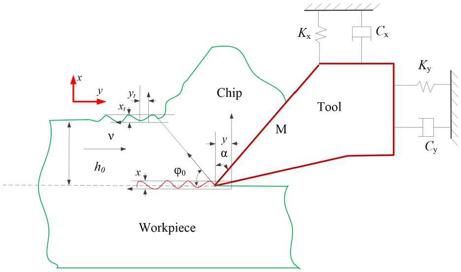
The geometry of two degree-of-freedom cutting system.
It is assumed that the shear plane is small enough. The length

As Figure 2 shows, a two degree-of-freedom system is considered here for convenience. The fundamental mechanics of metal cutting based on the Merchant cutting process model as presented.

The force of orthogonal cutting system.
In static cutting, the cutting force
The dynamic cutting force can be calculated from the geometric relationship in Figure 2. The dynamic cutting force

where,

where,
According to the theory of mechanical equilibrium, the cutting forces

For a given tool and the material of the workpiece material, we can establish a shear angle

where C is the material constant. It is insensitive to processing conditions.
According to the conclusion,
36
it is assumed, that this relation between the shear angle

Since the average friction coefficient between the tool rake face and the chip surface is mainly affected by the chip speed, the average friction coefficient between the tool rake face and the chip

where
The metal deformation of the cutting layer is roughly divided into three deformation zones: the first deformation zone is the shear slip zone, the second deformation zone is the fibrosis zone and the third deformation zone is the fibrosis and work hardening zone. The first deformation zone is the main deformation zone in the metal cutting process, which consumes most of the cutting power. Oxley 19 assumed that the shear band was a shear zone with a certain thickness considering the effect of work hardening, and a new cutting analysis model was established.
As the force of the tool on the cutting layer gradually increases, the shear stress on different planes in the cutting layer in front of the tool also increases. When the cutting force continues to increase, the shear stress on one of the planes reaches the yield strength of the material. With the phenomenon of work hardening, the cutting force continues to increase, and a shear zone is formed. The energy consumed in this process is P:

The shear angle

Compared with the classical Merchant 5 shear angle calculation model, the shear angle calculation model is more rigorous in theory to derive the minimum value of cutting power.
In the direction of cutting, the change in the dynamic shear angle is a function of the cutting speed, and according to the experimental results. The horizontal cutting force and the cutting force perpendicular to the horizontal direction are expressed by the following equation 24 :

where,

The calculation of dynamic cutting force is determined by static cutting coefficient
Model of cutting vibration mechanics
If it is assumed that the workpiece is regarded as a rigid body in the cutting process. Because the cutting tool vibrates under the action of cutting force, the tool and the workpiece system can be regarded as two degree-of-freedom systems under the action of cutting force. It is assumed that the elastic restoring force of the tool system is proportional to the vibration displacement

where,
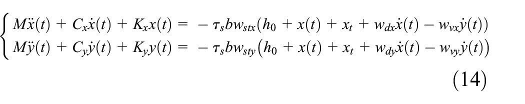
Substituting equation (12) into (13), the coupling dynamic equations of the tool in two directions equations are obtained.
Since the vibration amplitude of dynamic cutting is smaller than the cutting amount, according to a large number of studies. The surface cutting vibration texture can be regarded as a simple harmonic vibration. So the steady-state range can be expressed as:


where,

According to the dissipation theory, the excitation energy dissipation of the input dynamic system is the smallest in a vibration period. The system has the lowest stability. When the tool vibrates, the phase difference of the dynamic cutting force component acting on each direction of the system is given by

Substituting equations (17) and (18) into equation (14), we have

where,

The steady state solution can be expressed by

By substituting equation (20) into equation (12), the dynamic horizontal cutting force

Simulations and discussion
In order to verify the effectiveness of the right angle cutting force prediction model proposed in this paper. The used workpiece material is AISI 1045 steel. The relevant parameters
37
of the Johnson-Cook material model are listed in Table 1. The dynamic cutting process coefficient values are described from Altintas et al.
38
They are M = 0.561 kg, Kx = 6.48 MPa, Ky = 6.48 MPa, ξ = 0.015, h0 = 0.25 mm, b = 0.3 mm,
The Johnson-Cook parameters of AISI 1045 steel. 37

Characteristics of dynamic cutting force and machining surface
Figure 3 shows the dynamic cutting force in x and y directions. It can be seen from the Figure that the dynamic cutting force in y direction is larger than the x direction. The force amplitude in the x direction is 50 N, and x direction is 230 N. Combined with Figure 2, the cutting force in the y direction not only participates in the cutting of the material, but also bears the shedding from the matrix along the tool direction. Figure 4 are dynamic machining surface trajectory in x and y directions. It can be seen that the machining unilateral trajectory changes with the machining time at 0.15 mm, and the total machining amplitude changes at ±1 mm in x and y directions. The processing trajectory function obeys the Fourier function distribution. Figure 5 is force PSD in x and y directions. Through the power spectral density, the frequency components and frequency characteristics of the force signals in the x and y directions can be presented. They frequency is 29.4853 Hz.

Dynamic cutting force in x and y directions: (a) x direction and (b) y direction.

Dynamic machining surface trajectory in x and y directions: (a) x direction and (b) y direction.

Force PSD in x and y directions: (a) x direction and (b) y direction.
The influence of shear angle and cutting amount on cutting performance
Lin and Weng
39
pointed out that the variation in chip thickness and the periodic variation of shear angle
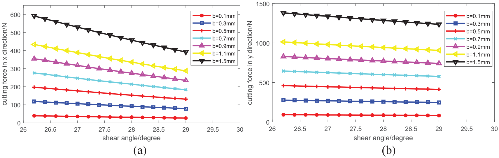
The influence of shear angle on cutting force: (a) x direction and (b) y direction.
Figure 7 shows the relationship of cutting force at a certain cutting speed. For cutting force

The influence of cutting speed on cutting force: (a) x direction and (b) y direction.
Cutting experiment and analysis
In order to measure the dynamic cutting force in different directions of x and y, an experimental device was designed to simulate the conditions of an unstable cutting process. The experimental device and principle of test are show in Figures 8 and 9, respectively. The experiment was simulated purely orthogonal machining. The basis of the measuring device is the triaxial forces sensor. It is rigidly connected to the tool holder of the machine tool through a connector. The working face of the force sensor is also rigidly connected to the cutting tool through the tool fixture. This structure can effectively ensure the cutting stiffness of the tool and accurately obtain the cutting force in three directions. At the same time, in order to measure the vibration of the tool when it is involved in cutting, a triaxial acceleration sensor is installed perpendicular to the working surface of the tool.
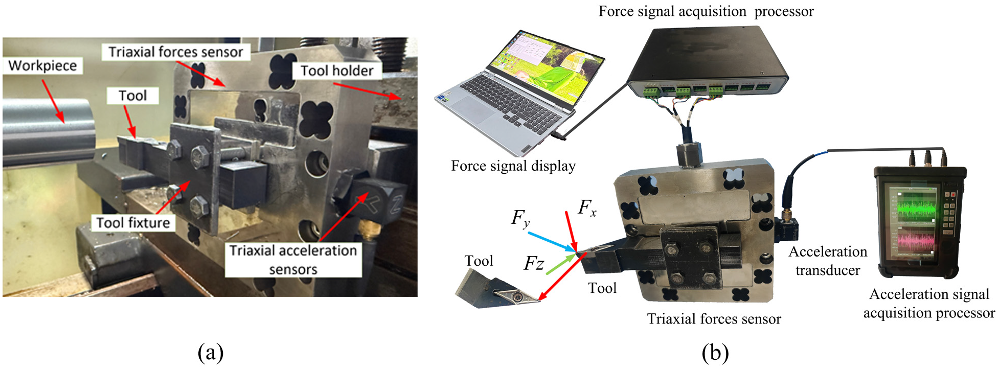
Cutting forces measuring device: (a) cutting system physical diagram and (b) cutting and signal acquisition system.

Principle of testing.
The semi-finished product for the test sample was a steel rod ø60 mm, AISI 1045 steel. During measurement, force sensor and acceleration sensor were recorded synchronously. The experiment used indexable turning tool and cemented carbide 35° triangular blade.
Analysis of experimental results of mechanical properties
The dynamic cutting force of the workpiece during machining was measured by a three-axis force sensor. The cutting feed speed is 80, 100, 120 mm/min respectively. The cutting amount are 0.25, 0.5 and 0.75 mm, respectively.
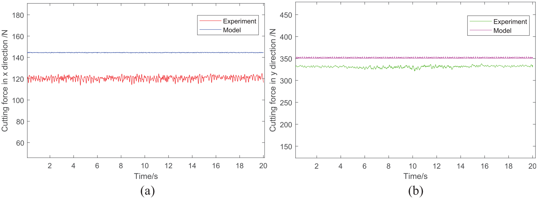
From Figures 10 to 15, they are shown the experimental and analytical dynamic cutting force comparison diagrams in the x and y directions at different cutting speeds and different cutting amount. Comparing the experimental and analytical curves in each Figure, it can be seen that the values of the two curves are close. The results show that the curves have the same development trend, and the simulation results are in reasonable agreement with the experimental results. The analytical method proposed in this paper to calculate the dynamic turning force is effective and feasible.

Comparison of predicted and experimental forces for h0 = 0.25 mm, v = 80 mm/min: (a) x direction and (b) y direction.

Comparison of predicted and experimental forces for h0 = 0.50 mm, v = 80 mm/min: (a) x direction and (b) y direction.

Comparison of predicted and experimental forces for h0 = 0.75 mm, v = 80 mm/min: (a) x direction and (b) y direction.

Comparison of predicted and experimental forces for h0 = 0.25 mm, v = 100 mm/min: (a) x direction and (b) y direction.

Comparison of predicted and experimental forces for h0 = 0.25 mm, v = 120 mm/min: (a) x direction and (b) y direction.
Comparison of predicted and experimental forces for h0 = 0.50 mm, v = 120 mm/min: (a) x direction and (b) y direction.
Table 2 is the average values of experimental and numerical cutting forces of
Average values of experimental and numerical cutting forces.

The standard deviations of the experimental values are also calculated. It can be seen that the standard deviation value is largest when the spindle speed is 120 mm/min in cutting forces of
The above research is only aimed at the characteristics of cutting force of 1045 steel under specific cutting conditions. If higher hardness materials (such as alloy steel, tool steel, hardened steel) are cut, it is expected to significantly increase the cutting force and tool wear. This requires a lower cutting speed or feed rate to maintain tool life or surface quality. If high-toughness materials are cut, it is easy to form long and tough continuous chips during cutting, which leads to winding problems and may aggravate the crater wear on the rake face of the tool. In terms of tool geometric parameters, increasing the rake angle usually reduces the cutting force, reduces power consumption and improves surface roughness. However, it will weaken the edge strength, reduce the heat dissipation volume, and may increase the vibration. Based on the basic principle of metal cutting and the existing literature research, it can be reasonably inferred that material properties (strength hardness, thermal conductivity, toughness, work hardening tendency) and tool geometric parameters (rake angle, clearance angle, main deflection angle, tool nose radius, edge inclination angle) have significant and complex effects on cutting force, vibration characteristics, tool wear mechanism and machined surface quality. Subsequently, the influence of the independence and interaction of key tool geometric parameters, such as rake angle, main deflection angle, tool nose radius, on the cutting process dynamics and results should be studied in amount.
Analysis of tool vibration characteristics experiment
In order to further evaluate the vibration characteristics of cutting tools and machine tools under different cutting parameters, the active acceleration parameters are used as the evaluation parameters, and the vibration acceleration parameters are obtained by the triaxial acceleration sensor mounted on the triaxial force sensor. Due to space limitations, only the vibration characteristics of the tool are studied under the condition that the tool feed rate is 80 mm/min and the cutting amount is 0.25, 0.50 and 0.75 mm.
The obtained characteristic parameters are processed by FFT in the x and y directions through the vibration post-processing software. The acceleration in the two directions is analyzed by cross power spectrum analysis, so as to accurately analyze the cutting vibration characteristics of the tool.
Figure 16 is the curve of the vibration acceleration value in x and y directions with time when the feed rate h0 0.25 mm. It can be seen from the Figure that the cutting vibration in two directions shows a periodic change, which conforms to the mechanism of cutting. The maximum amplitude of the vibration acceleration in the x direction is 12 m/s2, while the maximum amplitude of the vibration acceleration in the x direction is 40 m/s2, and the acceleration in the y direction is four times larger than the acceleration in the x direction, which is consistent with the cutting force results.
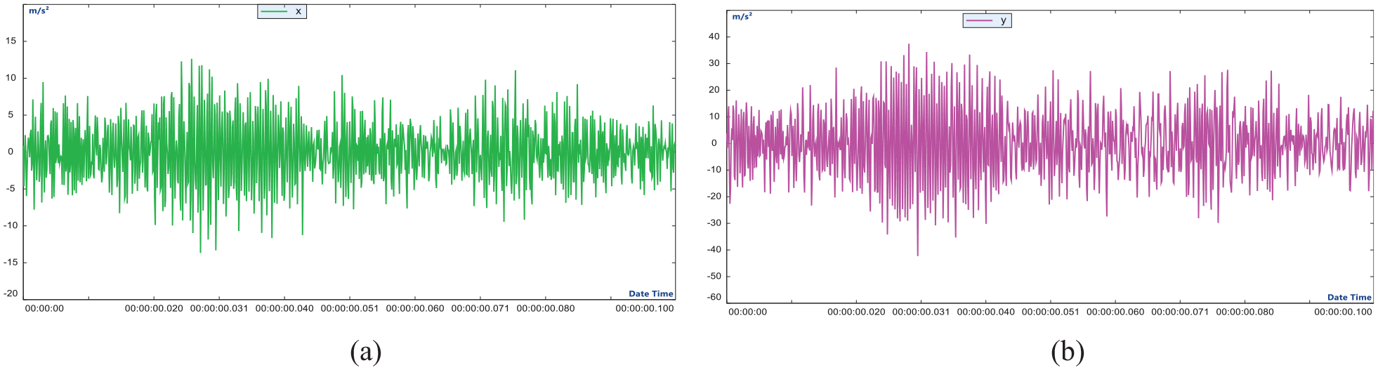
Acceleration signal: (a) X direction and (b) Y direction.
Fast Fourier vibration spectrum and cross power spectrum in x and y directions are shown in Figure 17. From the fast Fourier image of Figure 17(a), it can be seen that both x and y show frequency spectrum peaks at a frequency of 2580 Hz, while the spectrum in the y direction at a frequency of 1020 Hz is prominent, with a value of 0.517 m/s2, but the spectrum peak in the x direction is 0.06 m/s2. From the cross-power spectrum curve of Figure 17(b), it can be seen that the frequency peak spectrum is obvious at the frequency of 2580 Hz, the value is 8.29 m/s2 and the phase difference between the two directions is 23°, while the peak value is small at the frequency of 1020 Hz, the value is 0.83 m/s2 and the phase angle is 20°. From the above analysis, it is shown that when the tool is cut in this case, the vibration frequency of the tool holder is 2580 Hz, and the vibration frequency of the tool and the workpiece is 1020 Hz.
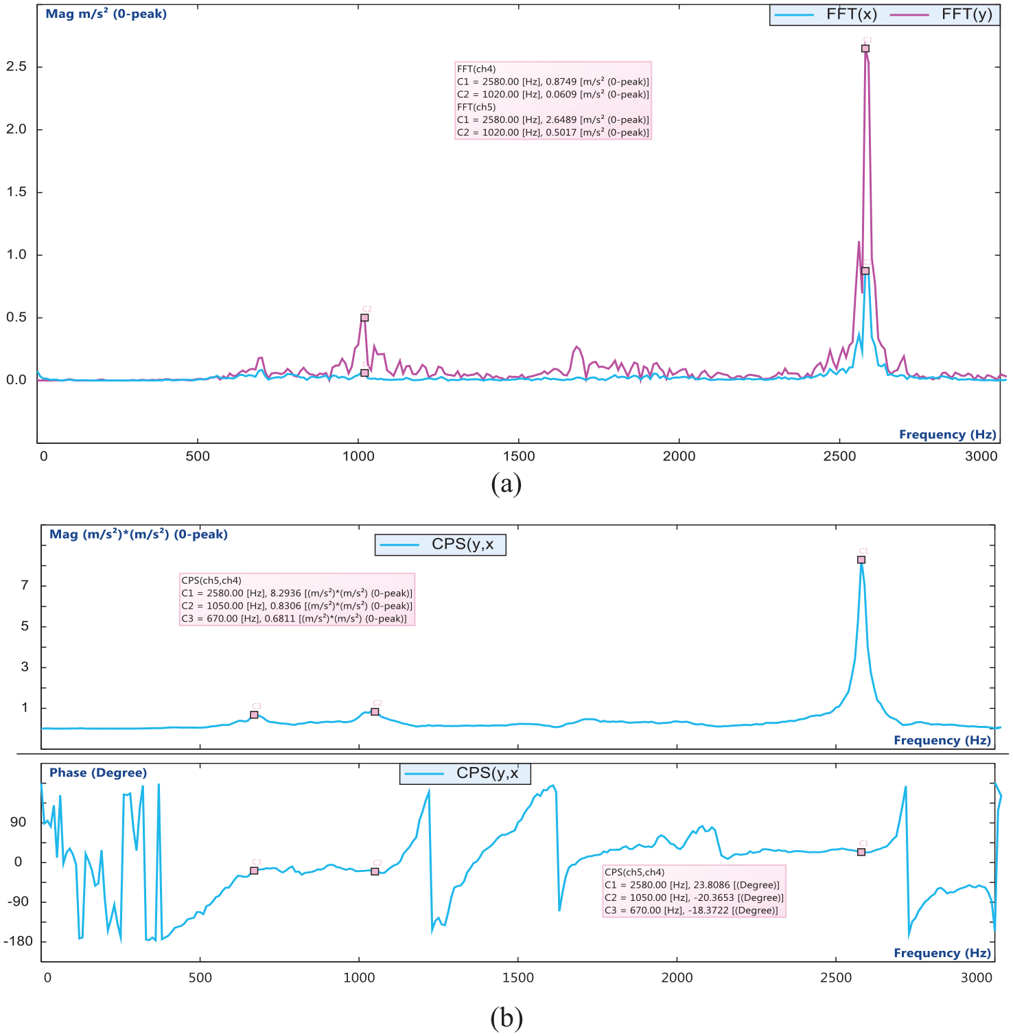
Vibration spectrum of x and y directions for h0 = 0.25 mm: (a) fast Fourier transform spectrum and (b) cross power spectrum.
Figure 18 is the fast Fourier vibration spectrum and cross power spectrum in x and y directions when the tool feed is 0.5 mm. From the fast Fourier image of Figure 18(a), it can be seen that both x and y show frequency spectrum peaks at a frequency of 2580 Hz, while the spectrum in the y direction 680 Hz, between 850 and 1020 Hz show continuous peak spectrum. The maximum peak reaches 2.517 m/s2, but the peak value of the spectrum in the x direction is less than 1 m/s2. From the cross-power spectrum curve of Figure 18(b), it can be seen that the frequency peak spectrum is obvious at the frequency of 2580 Hz, the value is 7.06 m/s2 and the phase difference between the two directions is 18°. The peak between the frequency of 625 and 1020 Hz is greatly increased compared with the spectral peak of the same frequency band when the cutting amount is 0.25 mm, the maximum value is 3 m/s2 and the phase angle is about 25°. From the above analysis, it is shown that when the tool is cut in this case, the vibration frequency of the tool holder is 2580 Hz, and the vibration frequency of the tool and the workpiece is between 625 and 1020 Hz. This is because with the increase of the cutting amount, the contact surface of the cutting edge of the tool is the largest, the cutting metal is subjected to complex elastic-plastic deformation and the side of the tool edge also flows, resulting in the complexity of the vibration characteristic frequency. At the same time, the frequency range of vibration characteristics during tool cutting is also more clearly defined.

Vibration spectrum of x and y directions for h0 = 0.50 mm: (a) fast Fourier transform spectrum and (b) cross power spectrum.
Figure 19 is the fast Fourier vibration spectrum and cross power spectrum in x and y directions when the tool feed 6799 is 0.75 mm. From the fast Fourier image of Figure 19(a), it can be seen that both x and y show frequency spectrum peaks at a frequency of 2580 Hz, while the spectrum in the y direction between 650 and 1700 Hz shows a continuous peak spectrum. The maximum peak reaches 4.03 m/s2, but the peak value of the spectrum in the x direction is less than 2.06 m/s2. From the cross-power spectrum curve of Figure 19(b), it can be seen that the frequency peak spectrum is obvious at the frequency of 2580 Hz, the value is 7.37 m/s2 and the phase difference between the two directions is 26°. The peak between the frequency of 650 and 1700 Hz is greatly increased compared with the spectral peak of the same frequency band when the cutting amount is 0.50 mm, the maximum value is 28.46 m/s2 and the phase angle is about 26°. From the above analysis, it is shown that when the tool is cut in this case, the vibration frequency of the tool holder is 2580 Hz and the vibration frequency of the tool and the workpiece is between 650 and 1700 Hz. This is because with the further increase of the cutting amount, the contact surface of the cutting edge of the tool participating in the cutting is larger, and the cutting metal is subjected to complex elastic-plastic deformation, showing the complexity of the vibration characteristic frequency. Due to the large amount of cutting, the tool holder and other parts are vibrated, which greatly reduces the surface accuracy of the workpiece.

Vibration of x and y directions spectrum for h0 = 0.75 mm: (a) fast Fourier transform spectrum and (b) cross power spectrum.
In order to further clarify the natural frequency parameters of the machine tool, the machine tool is no longer involved in the cutting, and the vibration characteristic parameters of the spindle at a certain speed are measured by the experimental method. The spindle speed is set to five segments, which are 100–200, 200–400, 800–800, 800–1600, 1250–2500 r/min. Figure 20 is the FFT spectrum of the tool holder in the x direction and the y direction under different setting intervals.

The FFT spectrum of the tool holder in x direction and y direction: (a) the spindle speed is 100–200 r/min, (b) the spindle speed is 200–400 r/min, (c) the spindle speed is 400–800 r/min, (d) the spindle speed is 800–1600 r/min and (e) the spindle speed is 1250–2500 r/min.
It can be seen from the acceleration vibration spectrum of the tool holder in the x direction and y direction under different speed sections of the spindle in Figure 20 that the vibration frequency of the tool holder in two directions is mainly 100 and 200 Hz when the machine tool is not involved in cutting. However, with the increase of the spindle speed, when the spindle speed is greater than 400 r/min, the vibration spectrum of the tool holder appears in the vibration spectrum of 2520–2700 Hz, but the amplitude of the vibration frequency is small, and the vibration amplitude in the Y direction is much larger than that in the x direction, indicating that the machine tool holder appears resonance phenomenon.
Comparison of Figure 20 machine tool to carry out different cutting volumes under the vibration frequency diagram of the machine in different directions can be concluded. The intrinsic vibration frequency of the machine tool holder is categorized into low frequency and high-frequency. When the spindle speed is low, the machine tool excitation vibration is weak. The system shows 100 and 200 Hz. With the spindle speed increase, the machine tool external excitation enhancement, the intrinsic frequency of the tool holder is outstanding. The vibration frequency is between 2520 and 2700 Hz. When the machine tool is involved in cutting, the machine tool resonance frequency strength is weakened, showing the main frequency of the vibration of the tool holder due to the cutting force and the tool cutting. By the machine tool in the non-involved in cutting and involved in cutting two cases of the spectrogram further shows that the vibration of the machine tool holder in the y direction is greater than the vibration of the x direction. The main reason is that the y-direction is the tool along the axial direction of the workpiece is involved in the cutting, which is caused by the vibration of the direction of the intensity of the main reason for this direction is large. Compared to the x direction, the tool in the y-direction of the stiffness is smaller than the x direction. According to the Hooke’s law that, 40 under the action of the same dynamic force, the lower stiffness will produce greater static deformation and dynamic displacement. On the other hand, the tool is clamped in the holder with different damping in different directions. If the damping in the y direction is lower than that in the x direction, it is easier to build up and maintain larger vibration amplitude under dynamic cutting conditions. One of the main mechanisms of cutting chatter is the regeneration effect. 41 The vibration of the current tooth will leave a vibration pattern on the surface of the workpiece. When the next tooth cuts into the surface with the vibration pattern, its instantaneous cutting thickness will change dynamically.
Conclusions
A study of the calculation method of static and dynamic forces in cylindrical turning has been presented by analytical method in this paper. A stability analysis of the chatter vibration with two DOF was carried out to estimate the influence of various parameters on dynamic cutting force and other aspects. It has been found that shear angle on cutting force has a great influence on the cutting force. The cutting force decreases with the increase of the shear angle in the x and y directions, respectively. Comparing the theoretical calculation and experimental results of the cutting force under a certain spindle speed and feed rate, the theoretical calculation is consistent with the experimental results. It is found that the error value of the calculation results is within 20%, and the calculation is effective. Through the analysis of tool vibration characteristic parameters, fast Fourier spectrum and cross power spectrum in x and y directions, it is shown that the vibration peak of cutting tool increases with the increase of cutting amount. The spectrum width of vibration is also increased. All those characteristics lead to the machining accuracy of the workpiece. Therefore, reasonable cutting amount in engineering application is beneficial to improve the machining surface accuracy.
However, in practical engineering, the metal cutting force is affected by many factors, such as the static and dynamic vibration characteristics of the machine tool, the clamping position of the metal cutting tool, the accuracy of the measuring instrument, the geometry of the tool and the degree of wear. The static and dynamic cutting force modeling process in this paper is based on a series of assumptions, which lead to the error between the analytical method and the experimental results. In this paper, both theoretical research and experimental research provide a theoretical and experimental basis for engineering applications.
Footnotes
Acknowledgements
The authors would like to thank Tianshui Normal University for their continuous support of the research work.
Handling Editor: Sharmili Pandian
Funding
The authors disclosed receipt of the following financial support for the research, authorship, and/or publication of this article: This research was supported in part by the Key Project of Science and Technology of Gansu Province (No.:22YF7GE169), the National Natural Science Foundation of China (No.:51565053), the University Industry Support Plan Project of Gansu Province (No.:2023CYZC-61).
Declaration of conflicting interests
The authors declared no potential conflicts of interest with respect to the research, authorship, and/or publication of this article.