
Abstract
The dynamic cutting force of a high energy efficiency milling cutter is an important indicator for evaluating the stability of the cutting energy efficiency. The existing cutting force analysis focuses on the main characteristics and influencing factors of the cutting force variation in the cutting process, ignoring the influence of the variation of the cutting layer parameters with the cutter tooth error in different cutting stages, and the dynamic cutting force variation is uncertain. In this research, the analytical model of the instantaneous cutting volume of a milling cutter was developed in order to obtain the time-frequency characteristics of the instantaneous cutting volume with the cutter tooth error. According to the sudden changes of the cutting force and the milling vibration, the variations were studied in different cutting stages. The dynamic cutting behavior sequences such as the instantaneous cutting volume, milling vibration, and dynamic cutting force were constructed to characterize the mapping relationship between the dynamic cutting behavior of a milling cutter. Based on these approaches, the identification method for the dynamic cutting force variation of a high energy efficiency milling cutter was proposed. The effectiveness of the method was verified by the results of the milling experiment and the dynamic cutting behavior response analysis. The results showed that the proposed method could effectively identify the variation and its control variables for the dynamic cutting force in the cutting process, and the method could provide a scientific basis for constructing the dynamic cutting force model of a high energy efficiency milling cutter.
Keywords
Introduction
With low energy consumption and excellent cutting effects, high energy efficiency milling cutters have been widely used in many fields.1–4 The frequent changes of the cutting force may cause unstable cutting, resulting in the decreasing of the cutting efficiency and reliability. The dynamic cutting force variation can effectively reflect the stress status of a milling cutter in the entire cutting process, and the identification of this variation plays a key role in the design of a high energy efficiency milling cutter and its process.
The dynamic cutting force is affected by the machine tool, workpiece, tool, cutting parameters, and other factors.5–15 Among them, the relationship between the dynamic cutting behavior is the key to unveil the dynamic cutting force variation. Different distribution of cutter teeth errors are inevitable in terms of manufacturing and installation. The diversity of the cutter tooth error distribution directly causes the change of the parameters of the instantaneous cutting layer, resulting in the continuous change of the dynamic cutting force. In addition, there are different impact processes from the cutting-in to the cutting-out of the workpiece, which will inevitably lead to the change of the relationship between the milling vibration and the cutting force. The comprehensive effect of the above factors makes the dynamic cutting force variation process of a milling cutter fuzzy.
Thus, the changes in the cutting layer parameters, milling vibration, and dynamic cutting force at different cutting stages under the effects of the cutter tooth error should be characterized and further connected effectively.
With the influences of the cutter tooth error, the characterization of the cutting layer parameters, milling vibration, and dynamic cutting force should meet the requirements of accuracy and generality. To date, the research on the dynamic cutting force has mainly been based on the empirical model,16,17 analytical model,18,19 and artificial intelligence prediction model.20–22 The above methods have guiding significance for the research on the dynamic cutting force, but they are limited by process conditions and process data, and they can only be used for specific tools and workpiece materials, which poses great limitations.
Compared with the other three models, the semi-analytical model is more suitable for the study of the dynamic cutting force. However, the influence of the variation of the cutting layer parameters with the cutter tooth error has often been ignored. As a result, it is also difficult to deduce the real variation characteristics of the cutting layer parameters, milling vibration, and dynamic cutting force with the cutter tooth error.
Therefore, based on the existing research on the dynamic cutting force, a model of the instantaneous cutting volume of a milling cutter under the influence of the cutter tooth error distribution is presented in this paper. Through the cutting experiment of high energy efficiency end mill, the variation of the milling vibration and cutting force were studied. The correlation between the instantaneous cutting volume, milling vibration, and dynamic cutting force under the effect of the cutter tooth error were unveiled using a gray correlational analysis method, which provided the basis for the construction of the dynamic cutting force model.
Variation of instantaneous cutting volume under the influence of the cutter tooth error
The changes of the instantaneous cutting volume of the milling cutter could comprehensively reflect the changes of the cutting layer parameters, as well as the effects of the milling cutter structure, cutting parameters, cutter tooth error, and its distribution during the whole cutting process, as shown in Figure 1. The meaning of the variables in Figure 1 is explained in the accompanying diagram.
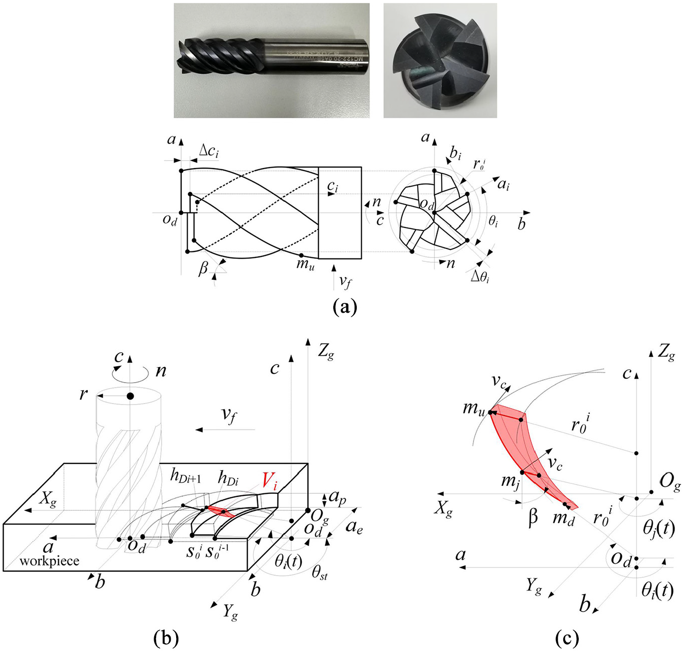
Cutter tooth error and instantaneous cutting layer parameters of end milling cutter: (a) structure of end milling cutter and its tooth error distribution, (b) cutting process of end mill, and (c) instantaneous cutting layer parameters of single cutter tooth.
As shown in Figure 1, the milling cutter tooth error directly affected the effective cutting edge length and the instantaneous cutting layer thickness, and it further changed the instantaneous cutting volume of the milling cutter (V), for which the instantaneous position angle of the cutter tip (θi(t)) could be written as:
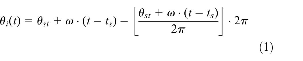
The instantaneous position angle (θj(t)) of an arbitrary point of the milling cutter cutting edge could be expressed as:

where,
The upper (mu) and lower (md) boundaries of the cutting edge under the effect of the cutter tooth error could be expressed as:
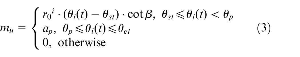
where, θwt is the initial cutting-out angle of the cutter tip, whose value was 3π/2. θet is the position angle when the cutter tooth completely separated from the workpiece, and θp is the position angle when the cutting depth is ap.


From equations (1)–(7), the instantaneous cutting volume of the milling cutter under the influence of the cutter tooth error can be expressed as:
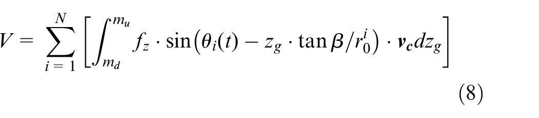
According to equations (1)–(8), the cutter tooth error changed the instantaneous position angle of the cutting edge and its instantaneous cutting boundary, which directly affected the edge length and the instantaneous cutting layer thickness of the cutter tooth that was instantaneously involved in cutting, thereby changing the instantaneous cutting volume of the milling cutter.
Based on the proposed model, the instantaneous cutting volume of the milling cutter could be acquired by combining the high energy efficiency milling cutter and its cutting titanium alloy process conditions provided by the enterprise.
The milling cutter was a solid carbide end milling cutter (MC122-20.0A5B-WJ30TF). Its structural parameters are shown in Table 1.
Structural parameters of milling cutter.
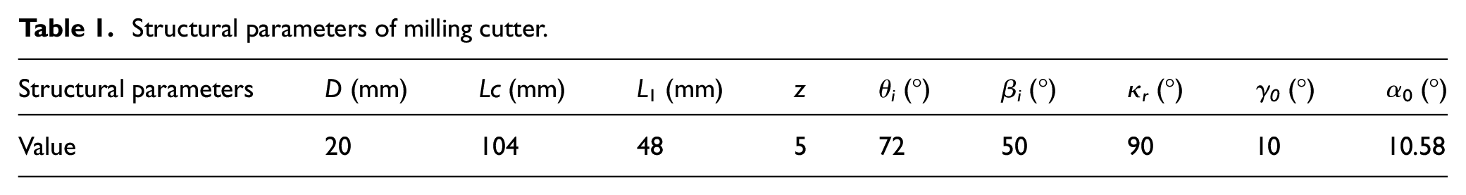
where, D, Lc, and L1 are the diameter, the total length, and the cutting edge length of the milling cutter, respectively. z is the number of cutter teeth.
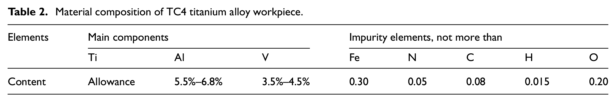
The titanium alloy specimen has dimensions of 200 mm × 100 mm × 20 mm. Its material composition is shown in Table 2.
Material composition of TC4 titanium alloy workpiece.
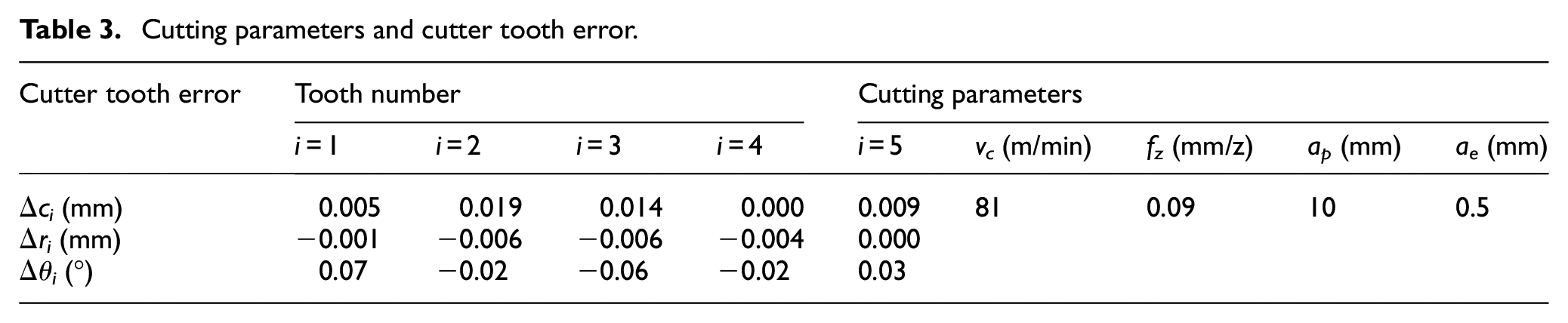
The cutting parameters and the test results of the cutter tooth error are shown in Table 3.
Cutting parameters and cutter tooth error.
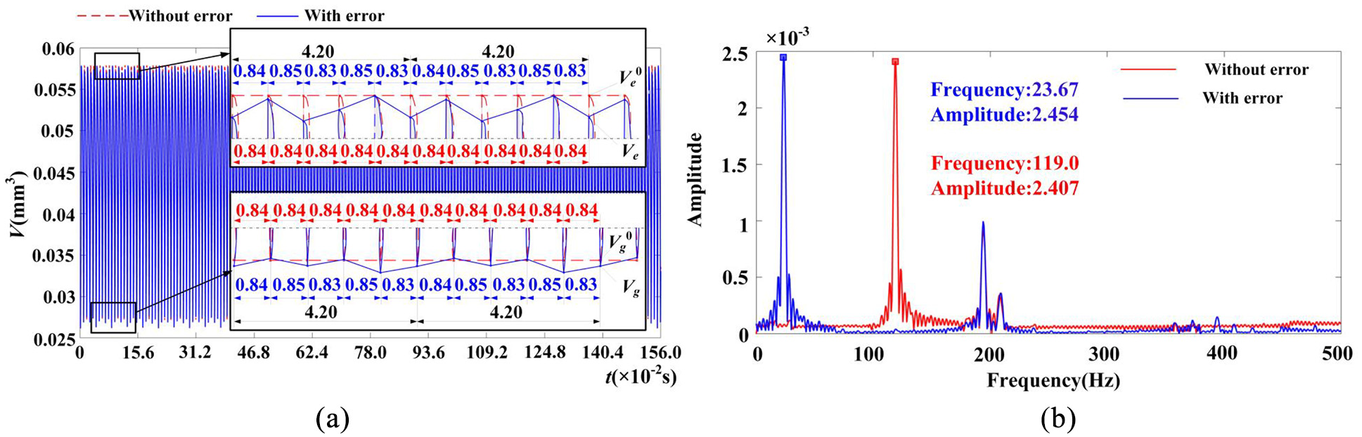
The time-frequency characteristic curves of the milling cutter instantaneous cutting volume were obtained as shown in Figure 2. The meaning of the variables in Figure 2 is explained in the accompanying diagram.
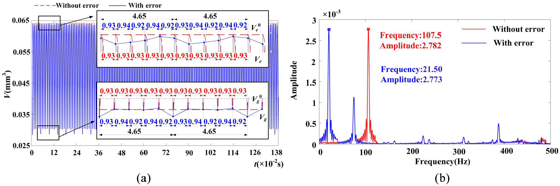
The time-frequency characteristic curves of the milling cutter instantaneous cutting volume: (a) time domain and (b) frequency domain.
It can be seen from Figure 2 that by comparing the time-frequency characteristics of the instantaneous cutting volume without the influence of the cutter tooth error, it was found that the root mean square (RMS) value of the instantaneous cutting volume changed from 0.0528 to 0.0525 mm3, the kurtosis changed from 2.0420 to 2.0574, and the dominant frequency changed from 107.50 to 21.50 Hz.
The results showed that although the cutter tooth error had no significant effect on the change intensity and the impact characteristics of the instantaneous cutting volume, it obviously changed the frequency domain distribution characteristics of the instantaneous cutting volume, resulting in the change of the variation period and the distribution characteristics of the instantaneous cutting volume of the milling cutter, which meant that the dynamic cutting force distribution characteristics changed accordingly.
Variation of milling vibration and dynamic cutting force in different cutting stages
In order to obtain the variation of the milling vibration and the cutting force, the end mill cutting experiment was carried out on a three-axis milling center (VDL-1000E) using the process conditions of the example given in Figure 2, as shown in Figure 3(a).
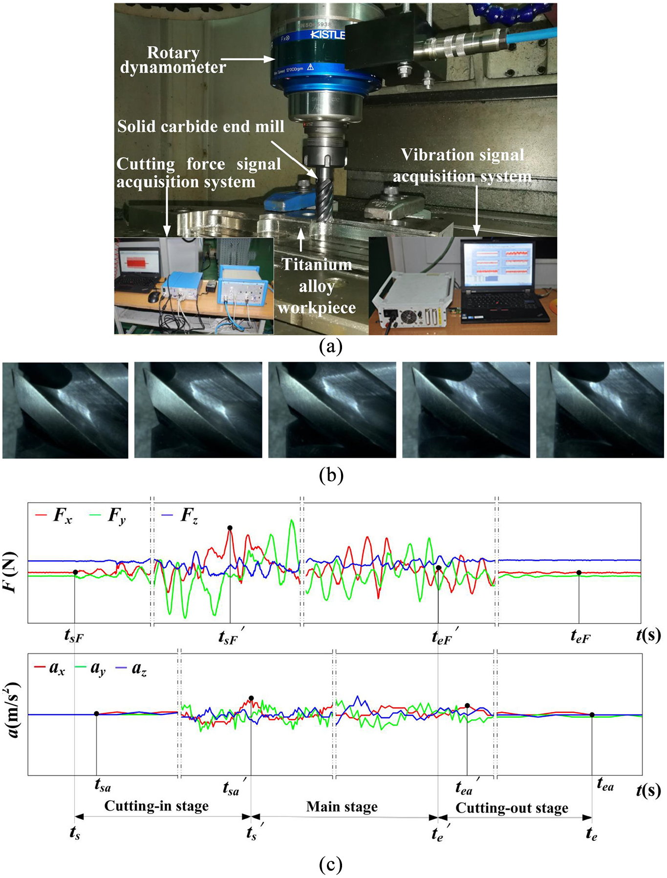
Milling experiment and cutting stage division: (a) cutting experiment of end mill, (b) wear state of milling cutter each cutter teeth, and (c) cutting stage division.
The clamping length of the end mill was 45 mm. In order to avoid the change of the milling vibration caused by the change of the clamping length, the total length of the milling cutter and the clamping length were kept unchanged in all experiments.
A PCB three-axis acceleration sensor and a DH5922 transient signal test and analysis system were used to detect the vibration acceleration signal in the milling process. The sensor was installed at the workpiece and its sensitivity was 25 mv/g.
The cutting force signals of the milling cutter along the direction of the feed rate, cutting width, and cutting depth were measured by a Kistler9171A rotating three-way force measuring instrument. The sampling frequency of the vibration and the cutting force signal was 5 kHz, with continuous sampling and a signal trigger.
After the experiment, an ultra-depth of field microscope (VHX-1000) was used to detect the tool tooth wear. The results showed that the cutter teeth were only slightly worn, as shown in Figure 3(b). Therefore, the influence of the milling cutter wear on the milling vibration and cutting force was ignored.
The experimental results showed that the period of the milling vibration and cutting force was 0.0465 s during the whole cutting stage. Its average property could not reveal the change process in the milling vibration and cutting force by using the average properties of the milling vibration and the cutting force in the whole cutting stage.
Therefore, according to the sudden change time of the milling vibration and the cutting force time-domain characteristic curve, the whole cutting stage was divided into the cutting-in stage, main stage and cutting-out stage, as shown in Figure 3(c). The variables in Figure 3, equations (9) and (10) are explained in the accompanying diagram.
Considering the difference between the characteristic time of the milling vibration and the cutting force, the characteristic time of the milling cutter in each cutting stage was determined as follows:


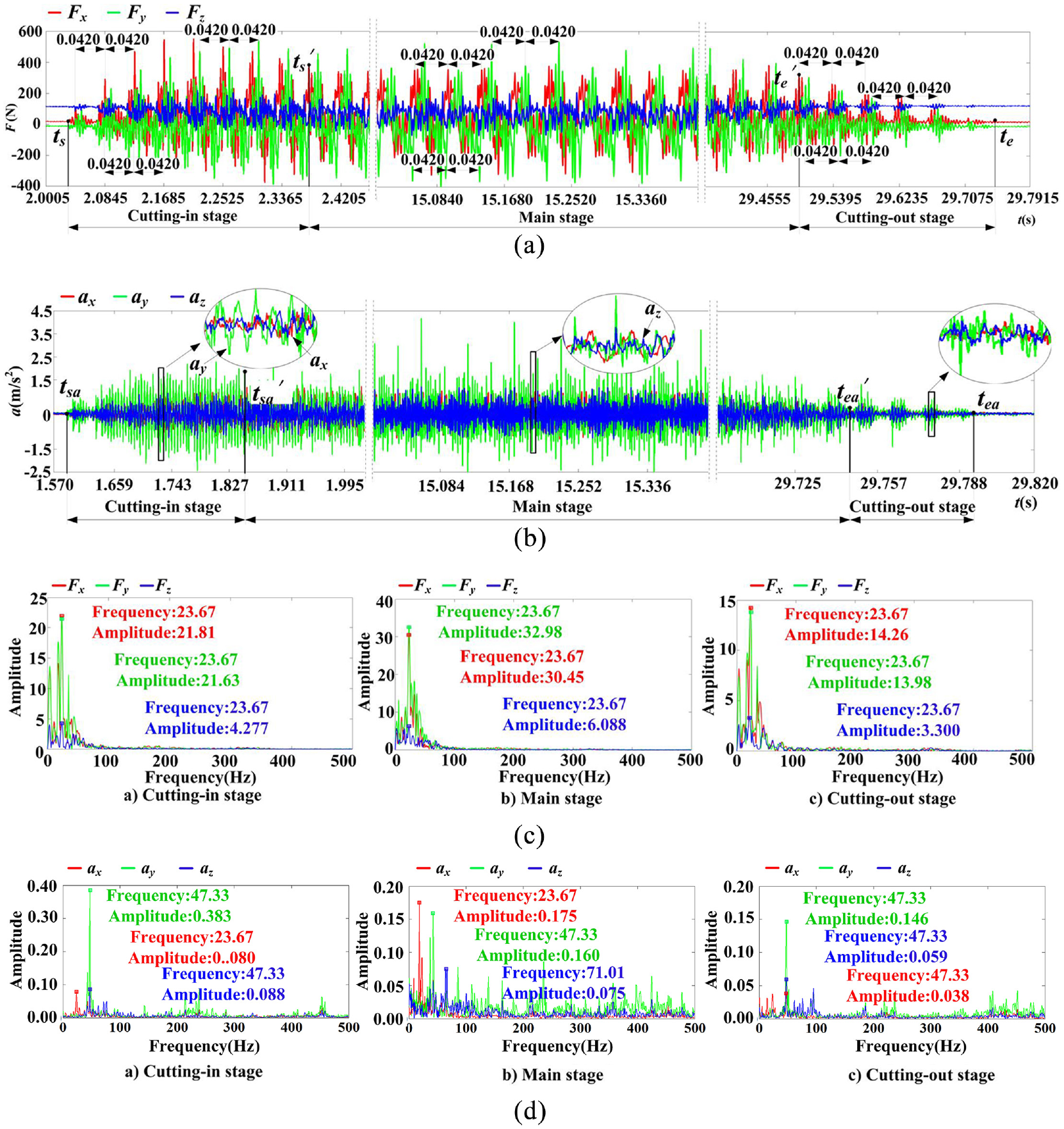
Using the proposed method, the cutting-in stage was 2.028–2.827 s. The main stage was 2.827–29.513 s. Additionally, the cutting-out stage was 29.513–29.933 s. According to the experimental results, the time-frequency domain signals of the cutting force and the milling vibration in different cutting stages were extracted, as shown in Figure 4.
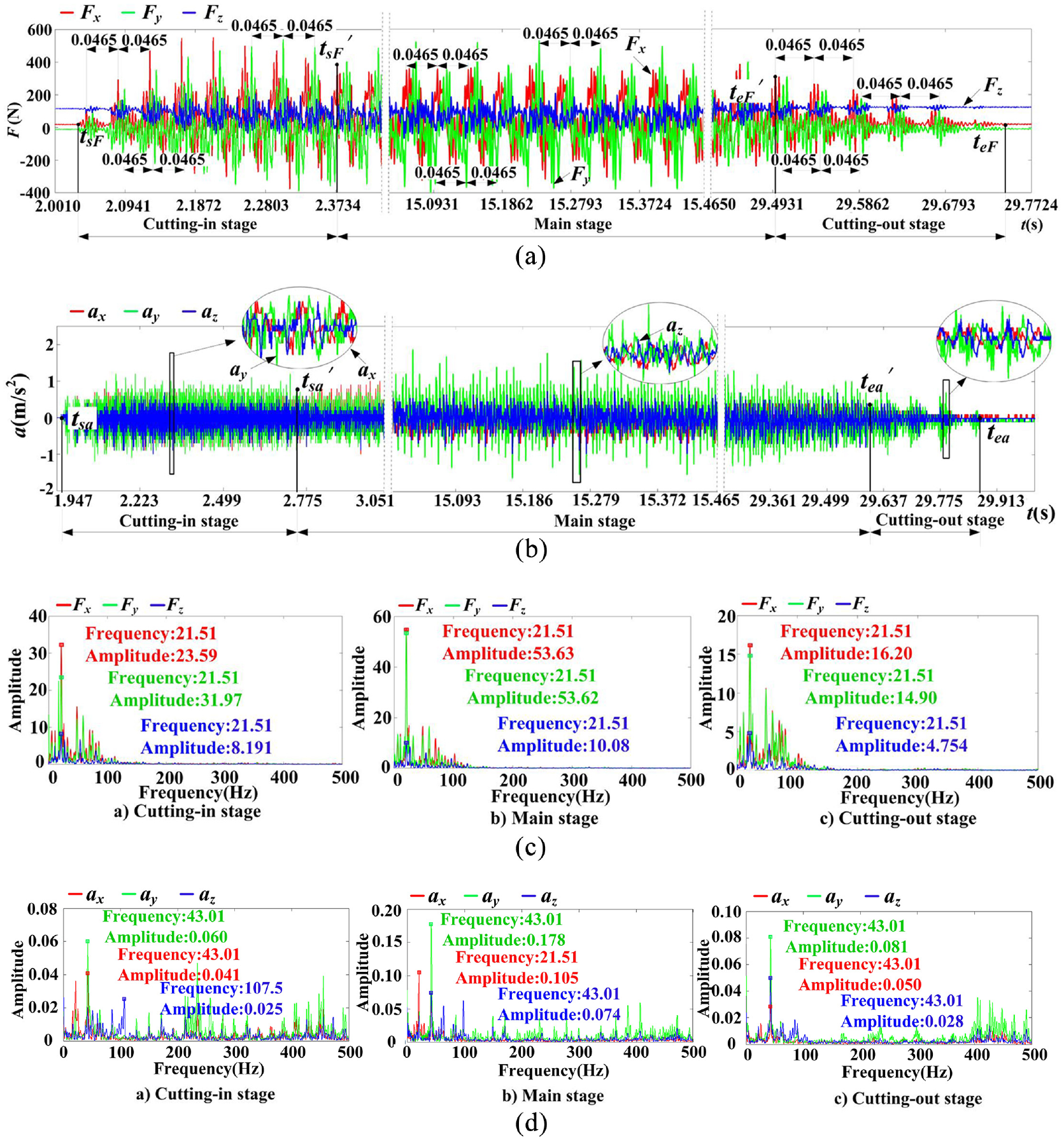
Time-frequency domain signals of milling vibration and cutting force: (a) the time domain signal of cutting force, (b) the time domain signal of milling vibration, (c) the frequency domain signal of cutting force, and (d) the frequency domain signal of milling vibration.
As shown in Figure 4, there were many characteristic times and different changing processes for the milling vibration and the cutting force in the whole cutting.
As shown in Figure 4(b), compared with the other two directions, the vibration acceleration amplitude in the cutting width direction was the largest. The main reason for this was that when the end mill of helix angle 45° was used to cut the side elevation with the cutting depth of 10 mm and the cutting width of 0.5 mm, the impact of the cutter teeth cutting into the workpiece was concentrated in the cutting width direction of the surface to be machined, and the vibration was significantly greater than that of the other two directions. Compared with the milling cutter with a small helix angle and cutting depth, the vibration caused by the axial impact of each cutting point of the cutter tooth was similar to the vibration acceleration amplitude of the feed direction. The time-frequency characteristic parameters of the milling vibration and the cutting force in different cutting stages were extracted, as shown in Table 4 and Figure 4.
The time domain characteristic parameters of the milling vibration and the cutting force.
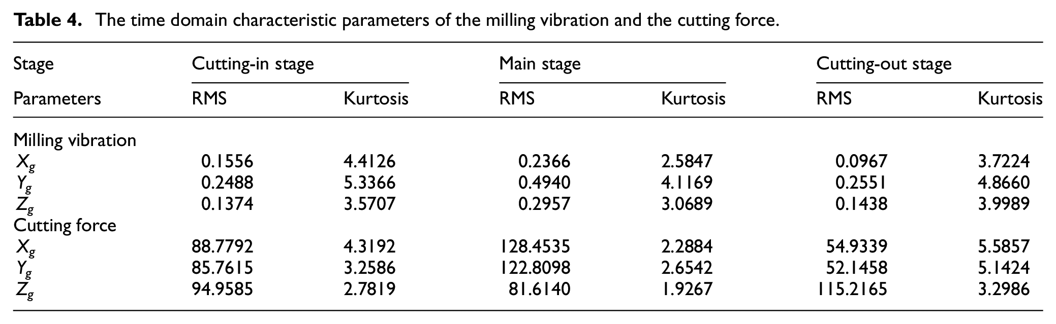
Based on Table 4 and Figure 4, the RMS of the milling vibration along the three directions showed the characteristics of small cutting-in and cutting-out stages and a large main stage, while the kurtosis presented the opposite characteristics. Compared with the dominant frequency of different cutting stages in other directions, the dominant frequency of the cutting-in stage in the cutting depth direction was obviously higher, while the dominant frequency of the main stage in the feed rate direction was at a lower level.
During the stage from cutting-in to cutting-out, the RMS of the cutting force in the cutting depth direction was different, and the kurtosis of the cutting force and the milling vibration in the three directions was similar. Although the dominant frequency of the cutting force was the same, its frequency distribution was different. At the same time, it was found that the dominant frequency of cutting force and the instantaneous cutting volume was consistent, but the dominant frequency had multiple relationships with the dominant frequency of the milling vibration.
The results showed that the distribution of the cutting force and the milling vibration were obviously different in each cutting stage, and the relationship between the cutting force and the milling vibration was in an unstable state. The distribution of the dynamic cutting force was related not only to the milling vibration but also to the instantaneous cutting volume with the cutter tooth error. It was necessary to further identify the relationship between the dynamic cutting behaviors in different cutting stages.
Identification of dynamic cutting force variation of milling cutter
For the different variations of the dynamic cutting force, milling vibration, and instantaneous cutting volume, in order to ensure a complete sampling length, the minimum sampling length was determined by using the minimum common multiple of the dynamic cutting behavior period. The inflection point of the dynamic cutting behavior was the characteristic time point. Based on the above, the variation of the dynamic cutting behavior was characterized by constructing the behavior sequence, as shown in Figure 5.
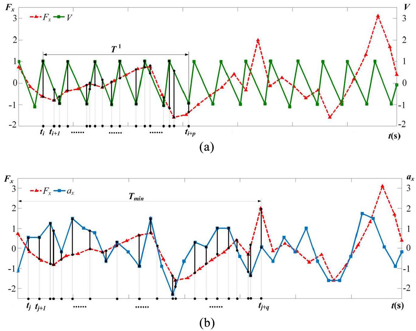
Dynamic cutting behavior and cutting force behavior sequence construction method: (a) instantaneous cutting volume and cutting force behavior sequence of milling cutter and (b) milling vibration and cutting force behavior sequence.
As shown in Figure 5, in order to facilitate the comparison, the dynamic cutting behavior signals were processed dimensionless. The meaning of the variables in Figure 5 is explained in the accompanying diagram.
Based on Figure 5 and the gray correlation analysis method, 23 the mapping relationship between the dynamic cutting behavior of the milling cutter was quantitatively characterized and identified, as shown in Figure 6. The meaning of the variables in Figure 6 is explained in the accompanying diagram.
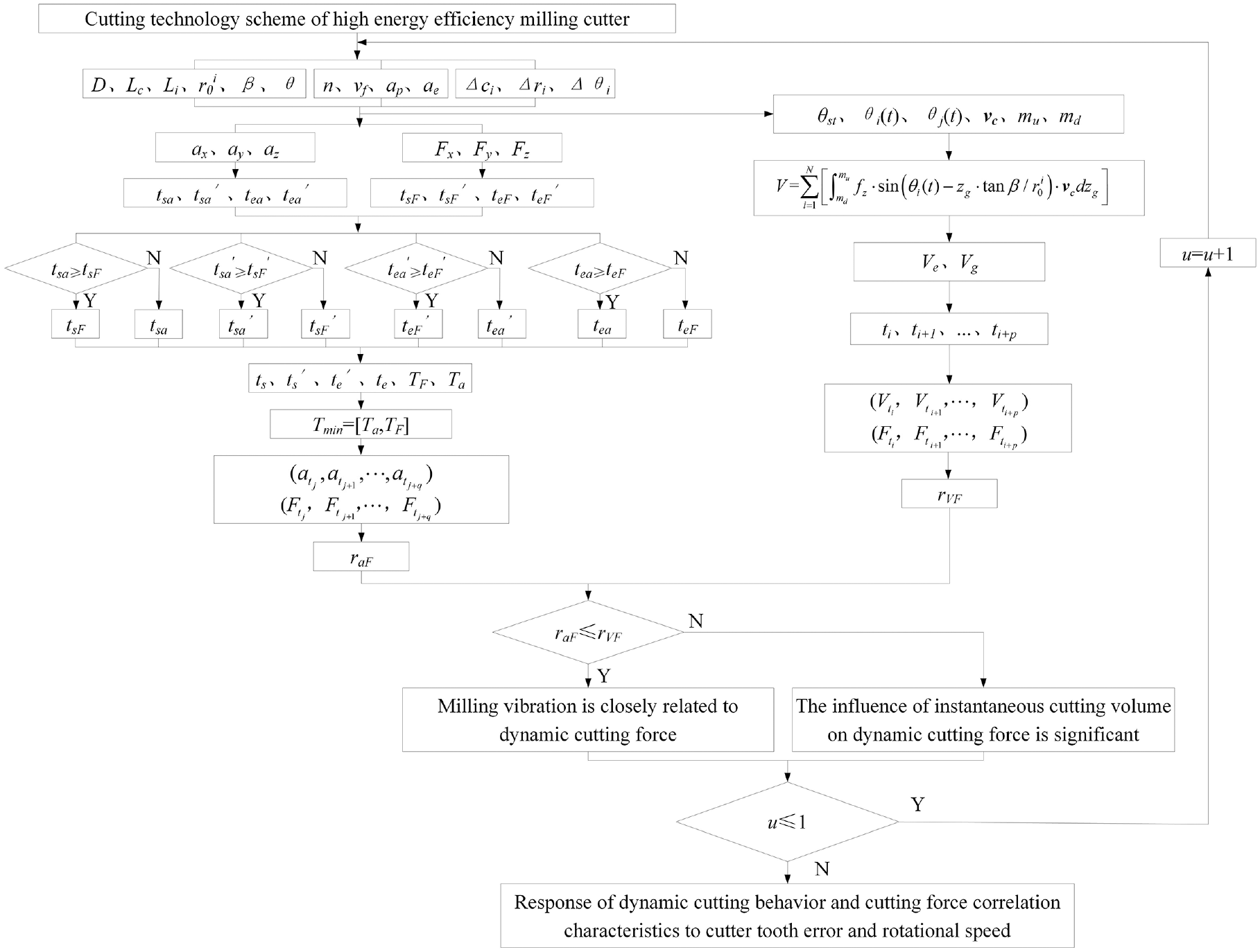
Identification method of dynamic cutting force variation of milling cutter.
Using the above-mentioned method, the correlation characteristics of the dynamic cutting behavior in Figures 2 and 4 were identified. The results are shown in Table 5. In the table, E is the cutter tooth error, and e is the error without the cutter tooth.
The correlation between the instantaneous cutting volume and the cutting force.
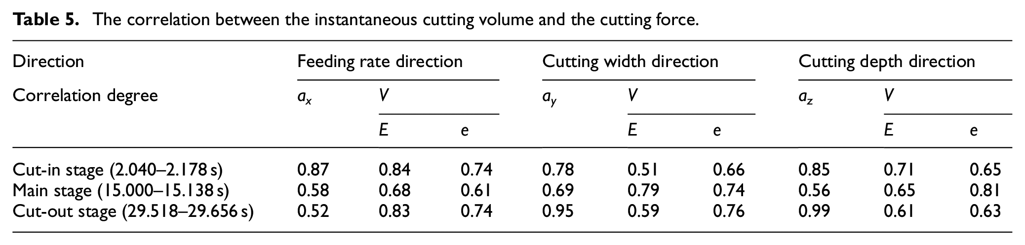
As shown in Table 5, the correlation degree was >0.50. More than 80% of the correlation degrees were >0.60, which indicated that dynamic cutting force distribution was closely related to the instantaneous cutting volume and the milling vibration. However, due to the different correlation degrees of three directions in different cutting stages, the relationships between instantaneous cutting volume, milling vibration, and dynamic cutting force were time-varying and directional.
According to Figure 2 and Table 5, the influence of the cutter tooth error on the dynamic cutting force not only changed the dominant frequency of instantaneous cutting volume, and then the distribution characteristics of the dynamic cutting force, but also changed the time domain characteristics of the instantaneous cutting volume, thus affecting the distribution of the dynamic cutting force.
The results showed that the influence of the instantaneous cutting volume on the dynamic cutting force variation between the correlation of the milling vibration and the dynamic cutting force could be identified by using the above method, which provided a basis for further identifying the process control variables of the dynamic cutting force variation and improving the cutting stability of the high energy efficiency milling of the titanium alloy structural parts.
Response characteristics analysis of dynamic cutting behavior of milling cutter
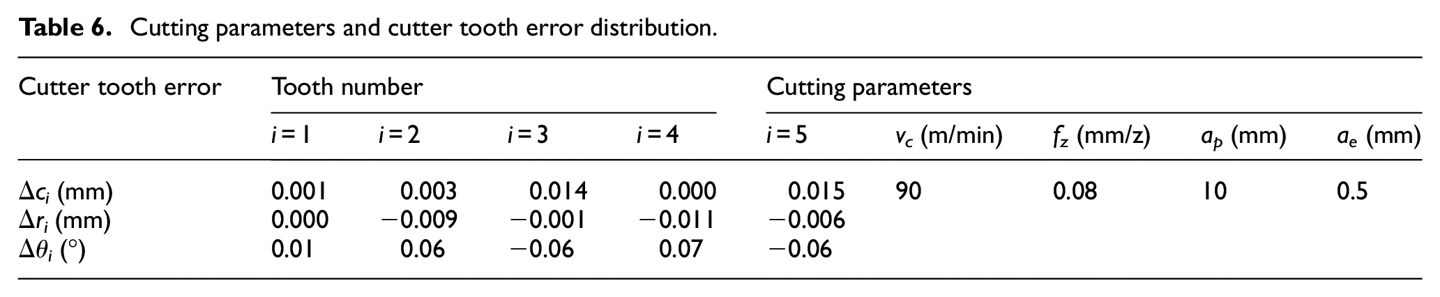
In order to verify the effectiveness of the above models and methods, Table 3 was taken as scheme 1, and the same milling cutter, workpiece, installation mode, and detection method as in scheme 1 were adopted. According to the technological requirements of the application enterprise for milling titanium alloy structural parts, the cutting depth and the cutting width were kept unchanged. The instantaneous cutting volume variation could be changed by increasing the milling cutter spindle rotation speed and the cutting speed, as well as changing the cutter tooth error distribution. In addition, the feed rate of each tooth could be reduced to keep the cutting efficiency unchanged. The instantaneous cutting volume solution and a milling experiment were carried out. Scheme 2 is shown in Table 6.
Cutting parameters and cutter tooth error distribution.
According to equations (1)–(8), the time-frequency domain characteristic curves of the instantaneous cutting volume of the milling cutter in scheme 2 were obtained, as shown in Figure 7.
Time-frequency characteristic curves of milling cutter instantaneous cutting volume (scheme 2): (a) time domain and (b) frequency domain.
According to Figures 2 and 7, the difference of the instantaneous cutting volume for schemes 1 and 2 was mainly reflected in the response of the time-domain period and the frequency-domain distribution for the milling cutter spindle rotation speed. The results showed that although the cutter tooth error distribution of the two schemes was different, compared with no cutter tooth error, the dominant frequency of the instantaneous cutting volume changed from being determined by the milling cutter spindle rotation speed and the cutter tooth number to being determined only by the milling cutter spindle rotation speed.
The experimental results for the cutting force and the milling vibration in different cutting stages that were obtained with scheme 2 are shown in Figure 8.
The time-frequency domain signal of the milling vibration and the cutting force (scheme 2): (a) the time domain signal of cutting force, (b) the time domain signal of milling vibration, (c) the frequency domain signal of cutting force, and (d) the frequency domain signal of milling vibration.
According to Figures 4 and 8, from the cutting-in stage to the cutting-out stage, except for the milling vibration kurtosis in the cutting depth direction, the milling vibration dominant frequency in the cutting width direction, and the dynamic cutting force dominant frequency variation characteristics were relatively consistent. The other time-frequency characteristic parameters showed obviously different variation characteristics. At the same time, it was found that the uneven distribution of the cutter teeth caused by the cutter teeth errors had a controlling effect on the dominant frequency of the instantaneous cutting volume, dynamic cutting force, and milling vibration, as shown in Figure 9.
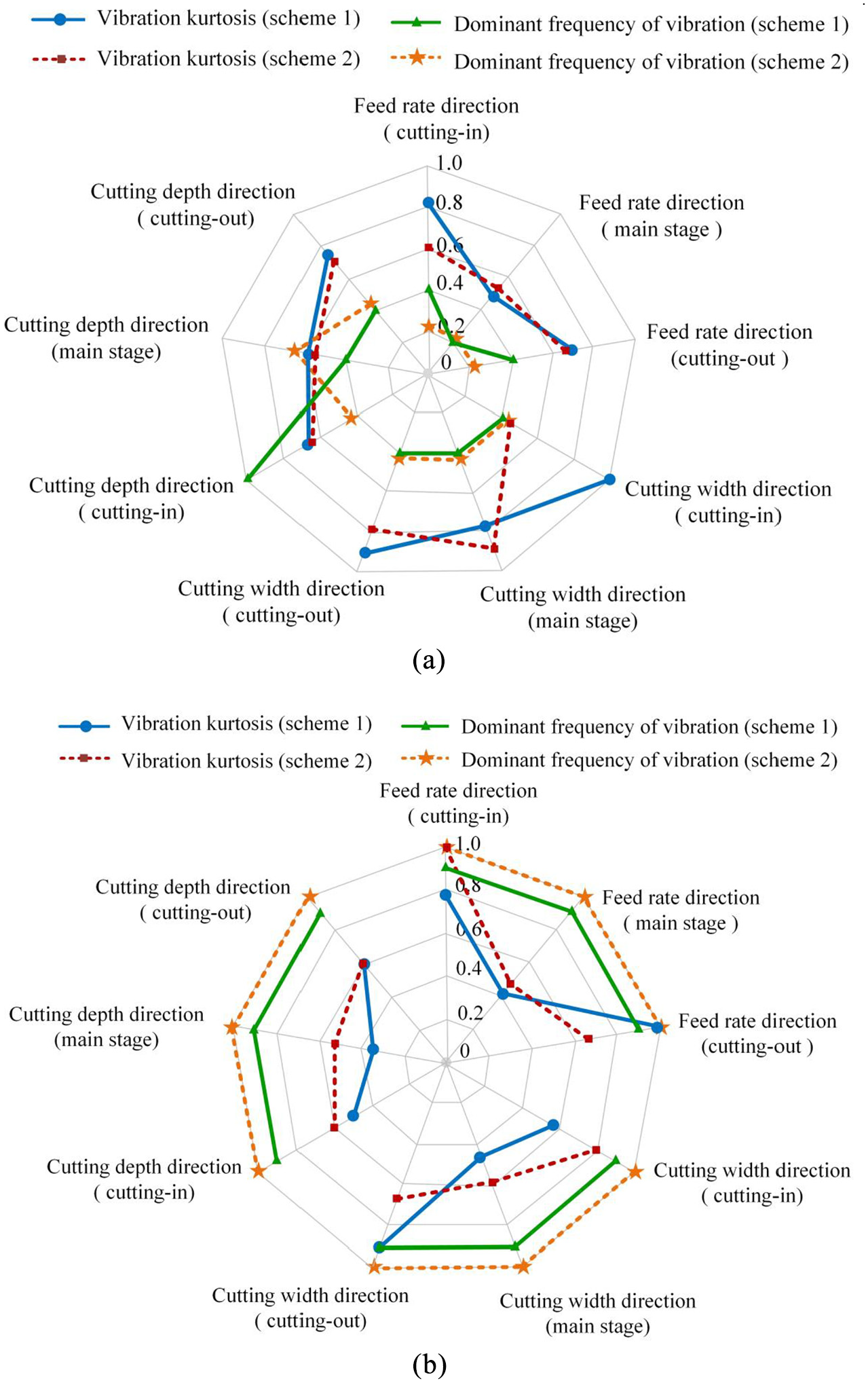
Distribution of time-frequency characteristic parameter response of milling vibration and cutting force: (a) response of milling vibration characteristic parameters and (b) response of cutting force characteristic parameters.
Using the method displayed in Figure 6, the correlation characteristics of the dynamic cutting force, instantaneous cutting volume, and milling vibration of the milling cutter shown in Figures 7 and 8 were identified, and the results were compared with those of scheme 1, as shown in Figure 10.
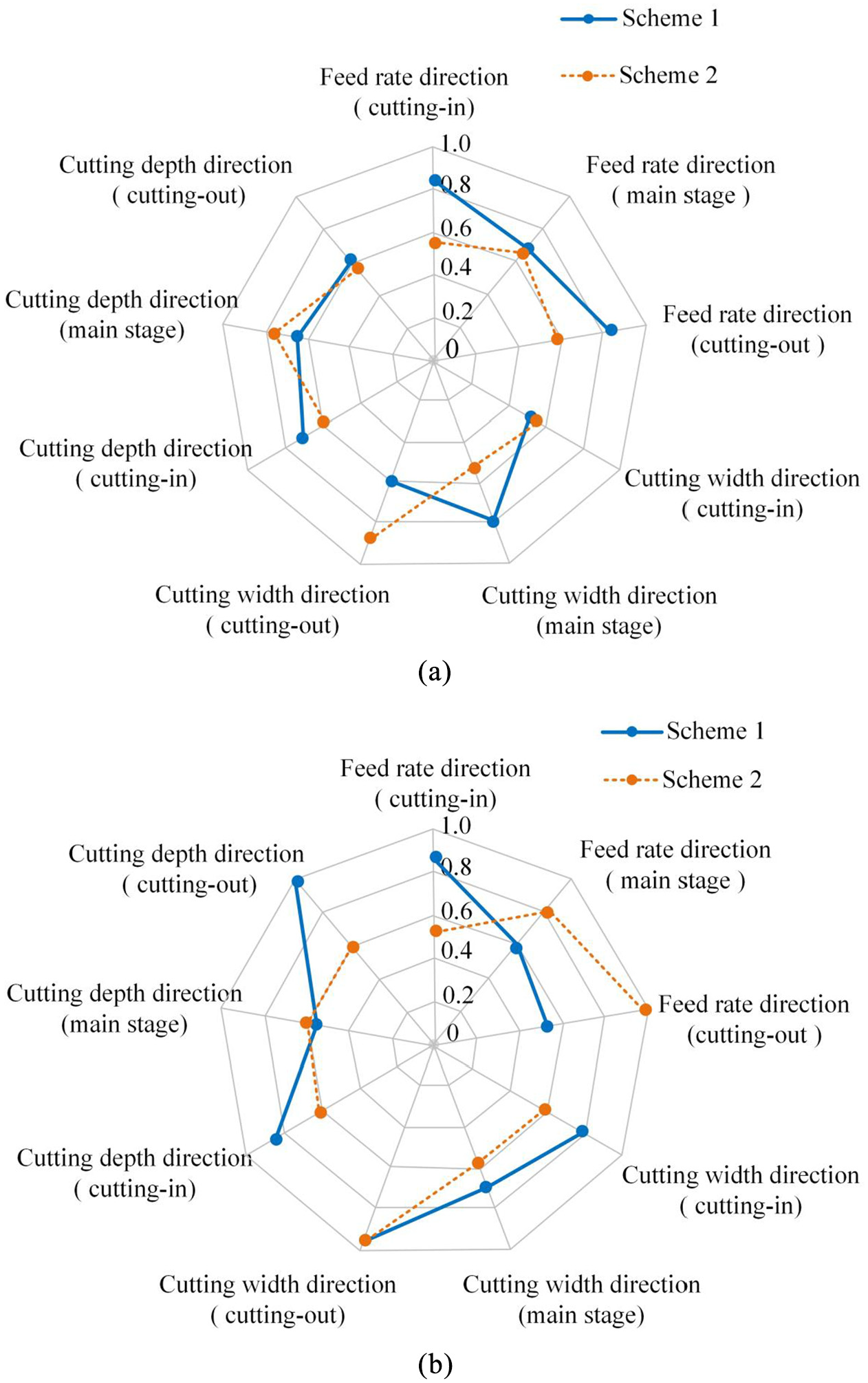
Correlation characteristics between dynamic cutting behavior: (a) correlation characteristics between cutting force and instantaneous cutting volume and (b) correlation characteristics between dynamic cutting force and milling vibration.
In Figure 10, compared with scheme 1 and 2, the correlation degrees of the dynamic cutting behavior of the milling cutter in three directions were obviously different, which indicated that the change of the milling scheme caused the response of the correlation among the cutting force, instantaneous cutting volume, and milling vibration, and it caused the dynamic relationship between the cutting behavior of the milling cutter to redistribute from cutting-in to cutting-out.
The results showed that the response of the dynamic cutting behavior of the milling cutter and its relationship to the process characteristic variables could be effectively identified by using the above model and method. This provided a basis for obtaining the multi-process variable collaborative design method to ensure the cutting efficiency and cutting process stability of the high energy efficiency milling titanium alloy.
Conclusion
In this study, a method for identifying the dynamic cutting force variation of high energy efficiency milling cutters was presented. The effectiveness of the method was verified with milling experiments. Some robust conclusions were drawn as follows:
An analytical model for the instantaneous cutting volume of the milling cutter was developed, and this model revealed the time-frequency characteristics of the instantaneous cutting volume of the milling cutter under the action of the cutter tooth error. The results showed that the cutter teeth error caused the uneven distribution of the cutter teeth, which led to the instantaneous cutting behaviors of the cutter teeth having different variations and then changed the time-frequency distribution characteristics. The model provides a method to effectively communicate the static process variables, such as the cutter teeth error, with the dynamic process variables, such as the cutting force.
The variation characteristics of the dynamic cutting force and the milling vibration in different cutting stages were revealed. The results showed that the relationship between the cutting force and the milling vibration was in an unstable state from cutting-in to cutting-out, and the variation of the dynamic cutting force was related to the instantaneous cutting volume under the influence of the cutter tooth error.
A method for identifying the dynamic cutting force variation based on the instantaneous cutting volume was put forward, and the time domain mapping relationship between the dynamic cutting behaviors of the milling cutter was quantitatively characterized. The results showed that the above method could be used to effectively identify the instability of the dynamic cutting behavior and the variability of the dynamic cutting force in the cutting process.
Process variables such as the milling cutter spindle rotation speed, cutter tooth error distribution, and feed rate per tooth had significant influence on the dynamic cutting behavior of the milling cutter and its correlation characteristics. Using the above models and methods, the time-domain mapping relationship among the instantaneous cutting volume, milling vibration, and dynamic cutting force could be changed through the collaborative design of the process variables, in order to regulate the variation characteristics of the dynamic cutting force and ensure the reliability of the high energy efficiency milling process for the large titanium alloy structural parts.
Footnotes
Appendix
Declaration of conflicting interests
The author(s) declared no potential conflicts of interest with respect to the research, authorship, and/or publication of this article.
Funding
The author(s) disclosed receipt of the following financial support for the research, authorship, and/or publication of this article: This work was supported by the Natural Science Foundation in China (grant number 51875145).