
Abstract
This research aims to optimize the drilling parameters of hybrid fiber-reinforced polymer (HFRP) composites made using a novel stacking sequence of carbon and glass fibers, with a focus on reducing delamination and surface roughness key defects that compromise structural integrity in industrial applications. The study employed vacuum infusion molded HFRP laminates and investigated the effects of drill bit material (HSS and Carbide), spindle speed (400–1000 rpm), and feed rate (0.1–0.8 mm/rev) using a Taguchi L32 orthogonal array. A hybrid optimization approach combining Grey Relational Grade (GRG), Principal Component Analysis (PCA), and Signal-to-Noise (S/N) ratio was used to evaluate multi-response outputs. ANOVA results revealed that feed rate and spindle speed significantly influence delamination, contributing 27.35% and 28.29%, respectively, while the drill bit material had the highest effect (64.01%) on surface roughness. The optimized parameters carbide drill bit, 630 rpm spindle speed, and 0.8 mm/rev feed rate achieved minimal delamination and surface irregularities. This study provides practical guidance for high-precision drilling of HFRP composites in aerospace, automotive, and structural industries.
Introduction
Fiber-reinforced polymer composite is gaining enormous attention day by day due to its superior properties, relatively low cost, and availability.1–3 The composite maker has resolved into a transition phase for their limitless use in all industries, and the progress is beyond imagination. Despite this, a new age in the advanced manufacturing sectors is appearing to emerge as the marketplace for composites. 4 Carbon Fiber Reinforced Composites (CFRP) are suitable for their wide variety of high-reliability applications. Properties like fatigue, corrosion resistance, lightweight, and high specific stiffness and strength made it excellent for aerospace, automotive, electronics, medical, and sports components. 5 However, it does have certain drawbacks, such as a high cost, a high electrical conductivity, and a low elongation at breaking. 6 On the other side, glass fiber reinforced composite (GFRP) is the type of fiber utilized most because of its low cost and frequently great manufacturing efficiency. 7 In addition to this, it has a moderate weight, intermediate strength, high elongation, and lesser stiffness. 8 In addition, industries require materials that are resistant to corrosion, such as chemical and marine pipelines, and GFRPs are frequently used. 9 GFRPs are just as strong as more modern inorganic fibers, but they are not as stiff due to the molecular structure. Technologies and industries are emerging to acquire hybrid composite materials (HFRP) made of carbon and glass fiber, which will be even more robust than they are at present. 10
When it comes to lightweight structural materials, HFRP materials have been popular for a long time. 11 These composites find immense uses based on their one-of-a-kind features, which are defined by a variety of physical attributes before the material is assessed for its reaction to the supplementary process of machining. Drilling is being used in all production techniques, whether they are conventional or non-traditional. 12 Cutting anisotropic substances combining glass and carbon fiber is a challenging operation because these materials have a tendency to produce holes with poor surface characteristics. 13 As a result the machining of this type of materials is an activity that is fraught with difficulty, which made the task more difficult by the fact that these materials are used. Moreover, Drilling on fiber reinforced composites can cause a variety of defects such as delamination, inter-laminar cracking, uncut fibers, surface roughness, fiber pull up, and fiber push out. 14 From this delamination and surface roughness is considered the most catastrophic flaw in drilling operation since it significantly lowers the stiffness and load-carrying capacity. These two quality issues are particularly critical in load-sensitive industries like aerospace and automotive manufacturing, where hole integrity is non-negotiable. These defects have the potential to affect the mechanical characteristics of the manufactured components, resulting in lower consistency. Nonetheless, this problem may be solved by selecting the appropriate cutting tool and maintaining the appropriate cutting conditions.15,16
Cutting parameters of drilling such as speed of the spindle, feed rate, thrust force, geometry of drill bit, tool diameter, and material are the most common causes of delamination and surface roughness.17,18 Eneyew and Ramulu and Geng et al. established that feed rate is the most significant factor influencing delamination, next to drill bit diameter.19,20 However, their study focused solely on unidirectional CFRP composites, without considering hybrid structures or varying fiber orientations, which limits the generalization of their results to more complex laminate architectures. In addition, high spindle speed with lower feed with help of a small drill bit diameter provided the least amount of delamination and surface roughness. Babu and Philip looked at how delamination in GFRP composites changed with spindle speed and feed rate and found that delamination largely driven by feed rate, and aided by high spindle speed. 21 This finding, while relevant, did not investigate tool material effects, which could be a dominant factor in hybrid composite drilling scenarios. Prasad and Chaitanya also conducted an experiment on GFRP to investigate how the cutting parameter effect the delamination. 22 Their research did not address multi-response optimization techniques, nor did it evaluate the combined effect of delamination and surface roughness, which are interdependent. The result shows that feed rate having the most significant effect on the delamination followed by the material thickness. According to the findings of Anand et al. and Geier drilling carbon-fiber reinforced polymer (CFRP) composites at high spindle speed results in improved quality when the feed is kept near to the ground, and the drill point angle is kept modest.23,24 Yet, these studies do not account for the stacking sequence in hybrid materials, which can drastically influence the damage mechanisms during drilling. Furthermore, Wang and Jia discovered that feed rate and spindle speed have the greatest impact on the surface irregularity of CFRP composite drilling. 25 Romoli and Lutey conducted an experiment on GFRP and CFRP laminates and found that, for both materials, the delamination factor increases with cutting speed and feed rate. 26 Although insightful, these analyses were restricted to single-material laminates and did not explore alternating stacking effects in hybrid systems. Always, the push-out delamination factor was greater than the peel-up delamination factor. Therefore, the feed rate was decreased to reduce the thrust force, resulting in less push-out delamination. In addition, Margabandu and Subramaniam carried out an investigation on thrust force, delamination, and roughness of the surface in drilling hybrid composites. 27 They discovered that feed rate and drill speed had an effect on the factor of delamination as well as surface roughness. Additionally, Tabet and Belaadi also conducted an experiment on thrust force, delamination, and surface roughness in drilling of hybrid composites and found that feed rate and drill speed affected the delamination factor and surface roughness. 28 However, neither of the studies used GRG-PCA optimization techniques or conducted statistical validation through ANOVA for multiple responses simultaneously. When the feed rate is increased, the tool will enter the work much more rapidly, which will result in an upsurge in the push force. As a consequence of the quick penetration, the inner layer has been affected and more damages will occur.29,30 According to Shanmugam et al., the tool geometry and material properties have an immediate effect on thrust force and delamination. 31 When drilling glass-carbon hybrid polymer composites, Tan et al. investigated the effects that feed rate, spindle speed, and drill shape had on the process. 32 Their results highlighted parameter influence but lacked an integrated optimization model to derive the best combination for both delamination and roughness. Collectively, the existing literature provides valuable insights into the effects of process parameters on delamination and surface finish in composite drilling. However, most studies are limited to single-material composites (CFRP or GFRP), do not consider stacking sequence effects in hybrid composites, or lack robust multi-response optimization. They discovered that the feed rate had a considerable influence on the drilling-induced damages that were incurred as a result of the drilling operation.
The settings for machining have a significant impact on the quality of the hole that is drilled. Having better control over the aspects has the ability to improve the efficiency of the drilling process and reduce the amount of material that is rejected. 33 In order to optimize those parameters a wide number of computer-based software approaches, like Taguchi and Response surface methodology, amongst others, are utilized. Aamir et al. used Taguchi Method and Fuzzy Logic Approach to optimize the process parameters in simulation based drilling operation of Aluminum 5083 (Al5083) plate. 34 Also in 2021 Sharma et al., and Rajamurugan et al. conducted a review on various optimizing methods and found that Taguchi and grey relational analysis (GRA) is the frequently used method followed by genetic algorithm (GA) for the optimization of cutting parameter during drilling operation.18,35 In another study Sur investigate the surface quality of CFRP plates drilled with standard and step drill bits by proposing the Taguchi combined with technique for order preference by similarity to ideal solution (TOPSIS) and Analytic Hierarchy Process (AHP) methods. 36 In addition ANOVA analysis was also performed to conclude the experiment. Tabet and Belaadi and Balaji et al. proposed artificial neural network (ANN) and response surface method (RSM) while optimizing the drilling parameter of jute fiber and cork-reinforced polymer machining.28,37 Moreover, Particle swarm optimization (PSO) was utilized for the purpose of optimization of carbon fiber reinforced polymer (CFRP) in drilling by Oedy et al. and Soleymani Yazdi et al.38,39 Principal Component Analysis (PCA) was also used in some cases to find the optimum values. 40
Amid the present works, extensive research has been conducted on the machining behavior of CFRP and GFRP composites, along with the fabrication of HFRP composites featuring different stacking sequences. However, only a limited number of studies have examined the drilling performance of HFRP composites with alternating stacking sequences and distinct fiber orientations. Such configurations present unique challenges in drilling due to the mismatch in mechanical properties between carbon and glass fibers, often leading to severe delamination and surface quality issues. Thus, it is essential to investigate these aspects in greater detail. To address this gap, the present study focuses on optimizing drilling parameters for a specially fabricated HFRP laminate with a novel stacking sequence (C-G-G-G-C-G-G-G-C), where carbon fibers are oriented at 0° and glass fibers at 90°. This design aims to balance mechanical strength while reducing common drilling defects. The research explores the effects of spindle speed, feed rate, and drill bit material on key responses: entry delamination (peel-up), exit delamination (push-out), and average surface roughness.
The experiments are structured using a Taguchi L32 orthogonal array, and multi-response optimization is carried out through a hybrid Grey Relational Grade (GRG) approach integrated with Principal Component Analysis (PCA). Taguchi’s signal-to-noise ratio is applied to assess response stability, while ANOVA is employed to determine the statistical significance and contribution of each parameter. Finally, a desirability function is used to simultaneously optimize all process responses. Therefore, the key novelty of this work lies in its comprehensive investigation of an alternating-stack HFRP laminate using integrated statistical and multi-objective optimization techniques. This study offers an effective framework to minimize drilling-induced damages and enhance hole quality, with direct applicability in aerospace, automotive, and structural composite applications.
Material and methods
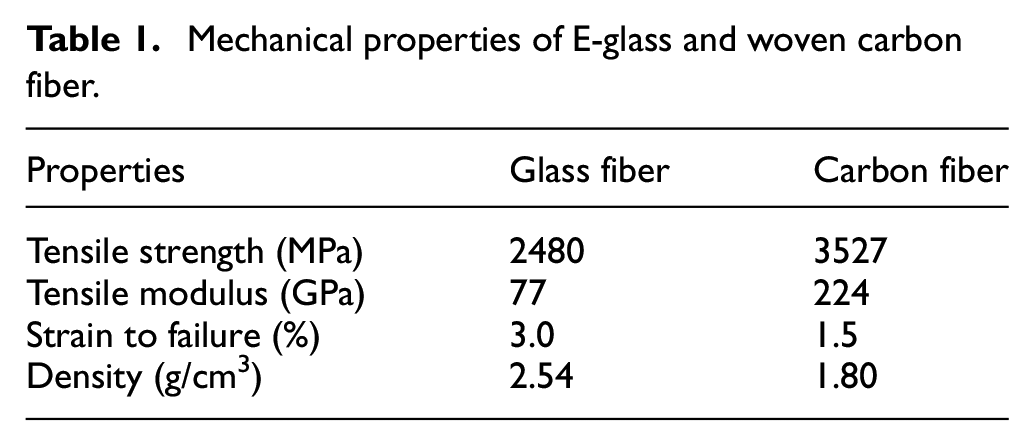
In light of what was discussed earlier, this study focus is on E-glass (BX600) and woven carbon fiber to fabricate HFRP composites to improve mechanical qualities while also minimizing the cost by using epoxy as matrix material. The physical and mechanical properties of E-glass and carbon fiber along with Epolam 2040/2042 matrix (epoxy resin and hardener) is showing in Tables 1 and 2 respectively. The thickness of both carbon fiber and glass fiber laminates were was 0.31 and 0.16 mm, respectively. To attain a higher flexural modulus, carbon fiber was used as the core and outer layers while The flexural strength of the outer skin is dramatically reduced as the number of glass fiber layers in the outer skin increases. 41 To attain a higher flexural modulus, carbon fiber was used as the core and outer layers while the flexural strength of the outer skin is dramatically reduced as the number of glass fiber layers in the outer skin increases. The final fabricated HFRP composite specimens were cut to dimensions of 70 mm × 25 mm × 3.75 mm for drilling and testing purposes.
Mechanical properties of E-glass and woven carbon fiber.
Physical properties of EPOLAM 2040/2042 matrix.

The vacuum infusion molding procedure was utilized in order to create the HFRP composites for this investigation shown in Figure 1. The preparation of the fiber cloth in accordance with the intended final size of the HFRP composite was the initial step in the process.

Vacuum infusion molding.
Before commencing the procedure, the glass mold was scrubbed with a thinner and a scraper to get it ready for use. After allowing the wax to cure for 15 min after being poured into the glass mold. The glass mold was covered with a strip of sealing tape that was at least 50 mm wider in width than the laminate itself. Then, following the specific laminar stacking sequence, fiber cloths were put over the wax inside the sealant tape region. The polymer mesh and peel ply were applied to the fiber clothing. Moreover, by using the sealant tape, the spiral tube was employed to arrange the resin input and outflow. These two tubes were connected, with the intake to the resin and the output to the vacuum chamber. To avoid any leakage, the vacuum bag was tightly fitted on the mold with the use of tape. After preparing the composite mold, the vacuum pump was started until a vacuum pressure of 80 kPa was reached in the pressure gauge. The pump was then turned off and the vacuum pressure was measured for 20 min to check for mold leakage. Later, the clamp on the inlet line was opened to allow the resin to flow into the mold. After impregnation, the clamp was closed to prevent additional flow through the entrance. For 12 h, the mold was left alone to solidify. Finally, the sample was placed in an oven set to 80°C for 6 h to complete the process and obtain the fabricated final composite model.
Mechanical properties (Tensile and flexural) of the HFRP composite was tested in accordance with ASTM standard (ASTM D 3039 and ASTM D790) to examine composite strength in compare to glass fiber reinforced polymer (GFRP) composite and carbon fiber reinforced polymer (CFRP) composite separately. The results are highlighted in Table 3.
Tensile and flexural properties of glass, carbon, and hybrid composite.

Measurement of surface roughness and delamination in drilled HFRP composites
In order to assess the quality of drilled holes in hybrid fiber-reinforced polymer (HFRP) composites, surface roughness and delamination were assessed. Surface roughness (R a ) was measured using a surface roughness tester (Mitutoyo Surftest SJ-210). Surface roughness (R a ) was quantified via a roughness tester following each drilling procedure, with measurements conducted around the drilled aperture and averaged to guarantee precision. Delamination at the hole entrance and exit was assessed using a digital microscope and image analysis software. Delamination was evaluated for both entry (peel-up) and exit (push-out) types using a trinocular optical microscope at 5× magnification. The delamination factor was determined using the formula F d =Dmax/D0, where Dmax represents the largest diameter seen as a result of delamination and D0 denotes the nominal drill bit diameter (8 mm). This enabled the researchers to measure the degree of delamination and evaluate the impact of drilling settings on hole integrity.
Taguchi method
Experimental design methods are too complex and hard to implement. With more machining parameters, more trials are needed. The Taguchi approach designs experiments with orthogonal arrays which reduce the number of tests and also the influence of outside factors. 42 In addition, Taguchi method reduces experiment time, money, and time to identify key factors. To meet this need, Taguchi builds a standard orthogonal array and gives the signal-to-noise ratio (sometimes written as S/N ratio). The signal-to-noise ratio (S/N ratio) is used in place of the standard deviation because when the mean decreases, the standard deviation does as well.


In general, the S/N ratio may be evaluated by making use of three different kinds of quality characteristics: nominal the best, smaller-is-better, and larger-is-better. Because reduced delamination and surface roughness for HFRP are what is sought after, the S/N (SB) ratio was used in this investigation. When the signal-to-noise ratio is the maximum possible, it indicates that the process parameters are functioning at their best possible level.
Grey relational analysis
The grey relational analysis calculates the absolute value of the data difference among sequences and may also be used to calculate their approximate correlation.43,44 When it comes to resolving doubts, contradictory data, or inadequate information, the grey approach is incredibly flexible and can adapt to almost any situation. In addition to this, it is quite easy to conduct an analysis of the connections that exist between the various data accumulations and to aid in the process of resolving the different characteristics that are under consideration. 45
Due to the fact that the response variables’ functions and units are different, in GRA it is required to modify the response variables in order to normalize the numerical values between 0 and 1 before any analysis. 46 Certain process responses may require minimization, while others may require maximization. The following two formulae are used to normalize the process response data, according to the requisites.


Here, i = 1, 2, …, m; k = 1, 2, …, n. For this study, m = 32 and n = 3.
Following normalization of process responses, the Grey relational coefficient (GRC), which represents the connection between the ideal and actual normalized response variables, may be determined using the following equation.

Where,
Principal component analysis
Principal component analysis, also known as PCA, is a sophisticated multi-variable statistical approach that is used in multi-objective optimization. PCA reduces the complexity, correlation, ambiguity, and dimensionality of the information by reducing and integrating several linked arrays into a few uncorrelated arrays and a principal component. 2 The principal component analysis (PCA) makes use of linear permutation in order to save as much different information as feasible. As a consequence of this, it is possible to preserve the original data while just doing a single-response optimization rather than a multi-response optimization. 47
The first step of PCA is to form a multi objective response matrix. PCA elucidates the structure of the variance-covariance matrix (M), which is obtained directly from this equation.

Here, i = 1, 2, …, m and j = 1, 2, …, n
The number of experiments is m while the number of response variables is n and x i (j) is the GRC of each response variable. For this study, m = 32, n = 3.
In the next step, the correlation coefficient matrix

Here, j = 1, 2, …, n and l = 1,2, …, n
The eigenvalues and eigenvectors of the correlation coefficient array can be calculated using following equation.

Here, k = 1, 2, …, n while
In the final step of PCA, the uncorrelated Principal Component can be calculated by following equation.

Since the first Principal Component always describes the highest variance of the data, the weight of each response is determined using eigenvector components associated with the first Principal Component.
GRG calculation
The grey relational grade (GRG) indicates the degree of correlation between experimental runs and is used to calculate the weighted mean of all experimental GRCs. Conventionally, the optimal condition is considered to be an experimental run with a larger GRG. This demonstrates the strength of the connection between the relevant experiments and the normalized value. 48
Using the first Principal Component as the weight of each performance characteristics, the weighted GRG can be calculated using the following equation:

Here,

Procedure for MRO by hybrid Taguchi-GRA-PCA method.
Experimentation
All of the drilling operations on the HFRP composite were completed using a radial drilling machine (Model: Z3032x10/1) that has a spindle power of 2.2 kW and is capable of reaching a maximum speed of 1000 rpm. Two 8 mm straight shank drill bits made of Carbide and High-Speed Steel (HSS) were used to cut the material which was prepared before with dimension of 70 × 25 × 3.75 mm. The HSS drill bit had a point angle of 118°, a helix angle of approximately 30°, and was uncoated. It is widely used in general-purpose drilling and served as a benchmark tool for evaluating performance on HFRP composites. Its moderate hardness and low cost made it a practical choice for baseline comparisons. The Carbide drill bit was a solid tungsten carbide twist drill, also with a point angle of 130° and helix angle of approximately 30°. It was uncoated, chosen for its higher stiffness, wear resistance, and reduced deflection during drilling, which are essential characteristics when machining fiber-reinforced composites prone to delamination and surface damage. The surface roughness of each run that was acquired from the experiment was measured with a roughness tester. Both the degree of cutting parameter ranges and the initial parameter values were taken from the manufacturer’s handbook and were chosen based on what was recommended for the material that was being tested. The various cutting settings together with their related degrees of operation are presented in Table 5. The Taguchi method, as well as the L32 (21, 42) mixed-level Orthogonal Array, were applied in order to cut down on the overall number of tests that were carried out. Table 4 presents the design of experiments (DOE) that was performed. After getting the process parameters from the experimental runs, the entry and exit delamination both were calculated by using following equation.

Here, Dmax represents the maximum diameter observed in the drilled hole and d represents the diameter of the drill bit.
Experimental values of process responses with Taguchi L32 array.

Selection of cutting parameters and levels
The selection of cutting parameters drill bit material, spindle speed, and feed rate and their respective levels was made based on a comprehensive review of existing literature, preliminary trials, and tool manufacturer’s recommendations. The chosen levels are representative of typical machining conditions for hybrid fiber-reinforced polymer (HFRP) composites and are summarized in Table 5. The rationale for each parameter is detailed below.
Process parameters and their different levels.

Drill bit material
Two types of drill bit materials High-Speed Steel (HSS) and Carbide were selected for comparative analysis. These tools were chosen due to their commercial availability and wide use in drilling operations involving composite materials:
Spindle speed (rpm)
Four levels of spindle speed 400, 630, 800, and 1000 rpm were selected. These values span the low to high-speed range of the Z3032x10/1 radial drilling machine, ensuring safe operation and coverage of a broad spectrum of cutting conditions.
Feed rate (mm/rev)
Feed rate levels were set at 0.1, 0.25, 0.5, and 0.8 mm/rev, covering both conservative and aggressive cutting scenarios. Low feed rates minimize delamination and thrust force but may cause tool rubbing and inefficient cutting. High feed rates increase material removal rate but risk inducing fiber pull-out, matrix cracking, and surface damage.
Result and discussion
Analysis of drilled holes
For drilling each specimen, an 8 mm drill bit was employed. Figure 3(a) and (b) displays the specimen following the drilling procedure for entry side and exit side respectively.

Drilled HFRP composite: (a) entry side and (b) exit side.
Once the drilling was complete, the delamination factor was checked using an optical trinocular microscope. Examining the drilled holes for flaws required a 5× magnification lens. Fiber pull-outs and uncut fibers, which are indications of delamination, can be observed in Figure 4.

Microscopic view of drilled holes.
Histogram and frequency analysis of process responses
Utilizing Minitab 17.0, a histogram analysis was carried out to check the frequency of the process parameter data points. The most frequent entry delamination data varies from 0.995 to 1.005, and the most frequent exit delamination data ranges from 0.985 to 0.995, as shown in the histogram in Figure 5 below. Additionally, the data for average surface roughness ranges from 1.35 to 1.45. The point of entry delamination was approximately 1.065, and the point of exit delamination was around 1.025, which is lower than the point of entry delamination. The roughest part of the surface was approximately 1.95.

Histogram of process responses: (a) entry delamination, (b) exit delamination, and (c) average surface roughness.
S/N ratios for process response
According to a number of earlier studies, spindle speed, feed rate, and drill bit type are the factors that have the greatest impact on entry delamination around the drilled hole.13,32 Drilling at the lowest spindle speed and highest feed rate produced the lowest entry delamination factor when compared to other drilling parameters. On the other hand, drilling HFRP composite at the lowest spindle speed and the maximum feed rate led to a higher delamination factor. 49
Entry delamination is most influenced by feed rate, followed by spindle speed and drill bit material, according to the S/N ratio response table, which supports earlier research. High feed rate and low spindle speed utilizing an HSS drill bit provide the least amount of entry delamination because entry delamination decreases with an increase in feed rate, a decrease in spindle speed, and a variation in the material of the drill bit.
The machining parameters and cutting tool material used to make the drilled hole have been shown in numerous articles to have an impact on the damages of drilled holes. 32 Evidently, spindle speed and feed rate have less of an impact on the exit delamination than do the carbide drill type on the testing results. Spindle speed is the most significant element impacting exit delamination, followed by drill bit material and feed rate, according to the S/N ratio table for exit delamination. The delamination factor values found in this study are in line with other studies on HFRP drilling, which found that exit (push out) delamination is more significant than entry (peel-up) delamination.50,51
From the S/N ratio table of average surface roughness, it can be seen that the average surface roughness is primarily influenced by the drill bit material, followed by feed rate and spindle speed. This finding is consistent with earlier experimental analysis of GFRP, which found that solid carbide drill bits had lower surface roughness. 45 Table 6 portrays the relative ranking of the process parameters in terms of S/N ratio to assure that the experimental findings aligned with the previous research.
Response table for S/N ratios of process responses (smaller is better).

The current study found that feed rate is the most dominant factor for entry delamination, which aligns with the findings of Eneyew and Ramulu 19 and Geng et al., 20 who reported that increased feed rates led to higher thrust forces and delamination during drilling of unidirectional CFRP composites. Our observed trend lower delamination at higher feed rates corresponds with the behavior seen in hybrid composites by Tan et al., 32 though their study used a different drill geometry, which may explain minor deviations in trend magnitude.
Analysis of Variance for process response
The influence of the process parameters on the process responses was verified by the ANOVA table for process responses. The parameters were significant with a 95% confidence interval at a p-value of 0.05. The three most important influencing factors for entry delamination, exit delamination, and average surface roughness were feed rate, spindle speed, and drill bit material. The conclusion reached from the S/N ratio analysis is consequently supported by this outcome. Table 7 shows that the feed rate has the most percent influence on entry delamination, with a maximum contribution of 27.3543%. Spindle speed and drill bit material are the two most important factors when it comes to exit delamination and average surface roughness, with a respective value of 28.2911% and 64.0086%.
Analysis of Variance table for process responses.
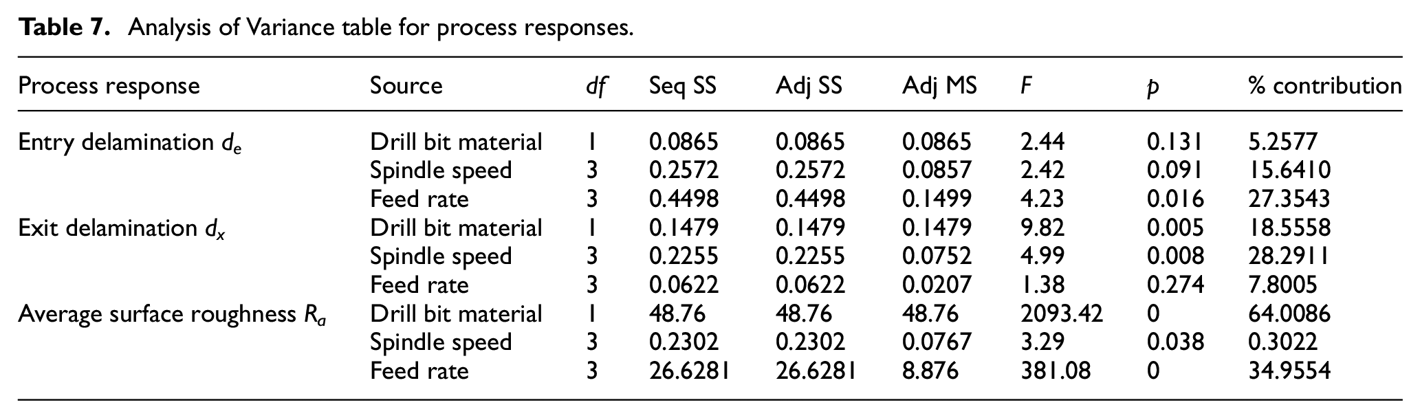
The ANOVA results show that surface roughness was most influenced by drill bit material, with carbide outperforming HSS significantly. This finding is consistent with results from Kumar et al., 45 who reported improved surface integrity in GFRP drilling using carbide tools. Moreover, Romoli and Lutey 26 also noted a significant reduction in roughness when tool rigidity and wear resistance were increased further supporting our observations.
Main effect plot for process responses
The main effect plot process responses are depicted in Figure 6 below, validating the earlier literature. It indicates that when feed rate and spindle speed increase using an HSS drill bit, entry delamination is decreased. Exit delamination, however, exhibited the reverse behavior when the spindle speed and feed rate were high. In summary, the least amount of entry delamination is achieved with a high feed rate, low spindle speed, and HSS drill bit, and the least amount of exit delamination is achieved with a low spindle speed, low feed rate, and carbide drill bit. For average surface roughness, it is also evident that surface roughness will decrease with rising feed rate and spindle speed. According to earlier literature, in the case of CFRP composite, the roughness diminishes as spindle speed rises. The built-up edge (BUE), which generated at low speeds, dissipates and chip fracture declines at higher speeds, which also causes the roughness to decline. 52

Main effects plot of SN ratios for process responses.
Summary of the influence of process parameters on various process responses
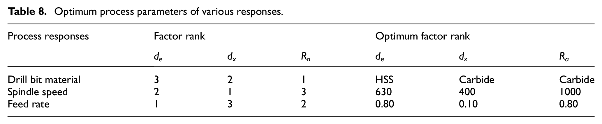
Table 8 shows the optimal process parameters for the various responses as well as their best rankings for each response. The table indicates that these varied input process characteristics have various effects on the various output responses. Additionally, various combinations of the process variables produced the best results for various combination. As can be observed, a carbide drill bit is best for exit delamination and surface roughness, while a feed rate of 0.80 mm/rev is best for entry delamination and surface roughness. Spindle speed varies once more depending on the response. Therefore, depending on the machining requirements, the relevance changes. By mixing the process parameters as needed, the ideal values for a given machining process can be found.
Optimum process parameters of various responses.
3D Surface plot of process responses based on process parameters
The interaction effect of feed rate and spindle speed on entry delamination is shown in Figure 7 of the 3D surface plot for entry delamination of HSS and Carbide drill bit. The interaction impact of feed rate and spindle speed differs for various drill bits. The minimal entry delamination is represented by the blue zone, while the maximum entry delamination is represented by the red zone. Here, the entry delamination rises with an increase in feed rate but rises with a drop in spindle speed. The 3D surface plot for exit delamination of HSS and Carbide drill bits then shows that the interaction impact of HSS drill bits with spindle speed and feed rate is more noticeable than that of the carbide drill bit. However, for both drill bits, the exit delamination likewise decreases as the spindle speed and feed do. As the feed rate and spindle speed increase, the average surface roughness for both drill bits are seen to be decreasing on a 3D surface analysis.

3D surface plot of different process responses.
Our surface plots suggest that exit delamination is minimized at lower feed rates and spindle speeds, a pattern similarly reported by Margabandu and Subramaniam 27 in their study on hybrid jute/carbon composites. The increased tool engagement time at lower parameters reduces the chance of fiber breakout, a mechanism also identified in Shanmugam et al. 31
Probability plot
The responses fall on a straight line on a normal probability plot indicating that the errors are normally distributed and confirms a high correlation between experimental and predicted values for the response. As the probability plots demonstrate the data points for entry and exit delamination are reasonably close to the fitted normal distribution line (the middle solid line of the graph); thus, the assumption of normality remains valid. But for surface roughness, the data points are slightly scattered. Therefore, the null hypothesis can’t be rejected that the data follow a normal distribution (Figure 8).

Probability plots of process responses.
Effect of process parameters on GRG
The process parameters were effectively optimized with regard to a single GRG rather than complex multi-responses. The GRG values fluctuate randomly within the range of 0–1. For Multi Response Optimization (MRO), the parameter levels corresponding to the highest GRG value must be chosen.
From the response table for GRG, it can be deducted that feed rate is the most crucial parameter, followed by drill bit material and spindle speed.
From Table 9 we conclude that mean of response at the optimal level was achieved which is used in confirmation test to calculate the predicted data for GRG.
Response table of S/N ratio for GRG (larger is better).
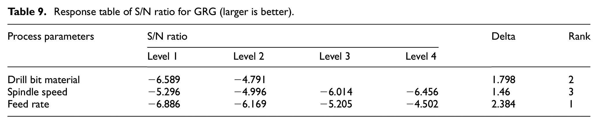
Table 10 reveals that feed rate exerts the most significant influence on the Grey Relational Grade (GRG), followed by drill bit material and spindle speed. The optimal parameter combination carbide tool, 630 rpm spindle speed, and 0.8 mm/rev feed rate yields superior overall machining performance.
Response table of means for GRG.

Additionally, it can be shown in Analysis of Variance for GRG in Table 11 that feed rate is the most important factor, contributing 38.37% of the total, followed closely by drill bit material, at 37.51%, and spindle speed, at 15.4%.
Analysis of Variance table for GRG.

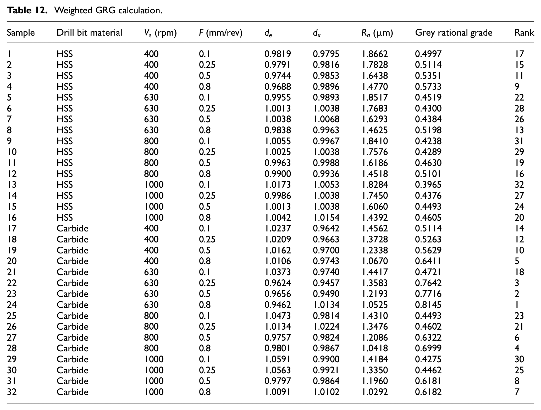
According to the main effects plot of the SN ratio for GRG, the highest GRG is produced by moderate feed rate, while the value of GRG increases with an increase in spindle speed and the maximum GRG value is obtained by HSS. Lastly, the weighted GRG was calculated for each run by utilizing equation (11) which is listed in Table 12 (Figure 9).
Weighted GRG calculation.

Main effects plot of SN ratios for GRG.
According to Table 12, a carbide drill bit with a spindle speed of 630 rpm and a feed rate of 0.80 mm/rev produces the least amount of entry/exit delamination and surface roughness.
Confirmation test
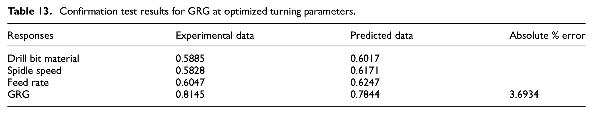
Confirmation tests were conducted to validate the improvement in performance characteristics provided by Taguchi-based GRA. After determining the optimum level of the cutting parameters, the predicted value of GRG at that level may be determined as per following equation

Here,
Confirmation test results for GRG at optimized turning parameters.
Conclusion
The purpose of this research was to determine the optimized drilling process parameters for HFRP composite, which was composed of CFRP and GFRP composites and was drilled using high-speed steel and carbide drill bit. Drill bit material, feed rate, and spindle speed were considered as process parameters, whereas entry and exit delamination and average surface roughness were considered as process responses. Results acquired from the above analysis are summarized as follows:
Hybrid composite was fabricated successfully with vacuum infusion technique and the mechanical properties found are comparable with previous studies.
According to the S/N ratio and ANOVA analysis, the feed rate, spindle speed, and drill bit material were the main influences on entry delamination. The amount of entry delamination decreases significantly with an increase in feed rate. The most important determining factor for exit delamination, followed by drill bit and feed rate, was spindle speed. Reduced spindle speed also results in less exit delamination. Finally, the drill bit material, feed rate, and spindle speed were each considered for surface roughness. The ideal drill bit had a minimum amount of surface roughness, and that was carbide.
Grey Relational Analysis and Principal Component Analysis were combined to transform the multi-response optimization problem into a single objective optimization. Using a carbide drill bit at 630 rpm and a feed rate of 0.8 mm/rev, the hybrid GRA-PCA analysis determined the ideal process parameters for minimizing defects, where entry delamination was 0.9462, exit delamination was 1.0134, and surface roughness was 1.0525 m.
The difference between experimental data and projected data when determining the grey relational gradient was 3.69%, validating the hybrid GRG-PCA approaches improved performance features.
In comparison to the signal to noise ratio analysis, hybrid GRG-PCA reveals the best optimal process responses. This analytical approach is superior to others since it uses integrated GRG-PCA to find the correlation between the parameters.
Future research should focus on expanding the understanding of drilling behavior in hybrid fiber-reinforced polymer (HFRP) composites and promoting further studies in this developing field. Investigating advanced cooling and lubrication methods, such as cryogenic cooling, minimum quantity lubrication (MQL), or nano-fluid-assisted techniques, can help minimize thermal damage and delamination during drilling. Exploring innovative drill geometries and coatings may also contribute to improved hole quality and extended tool life. Further studies should examine a wider range of hybrid stacking sequences, fiber orientations, and matrix materials to assess the generalizability of optimized drilling parameters. Incorporating real-time monitoring systems such as acoustic emission, force sensors, or vibration analysis could support the development of intelligent, adaptive machining strategies. Additionally, it is essential to correlate drilling-induced damage with the mechanical performance of finished components through fatigue, tensile, and impact tests. These efforts would not only refine machining parameters for better quality and efficiency but also provide critical insights into the structural reliability of drilled composite parts. Encouraging more interdisciplinary research in this area will be vital to advancing manufacturing practices and supporting the broader industrial application of HFRP composites in sectors like aerospace, automotive, and marine engineering.
Footnotes
Acknowledgements
The authors thank Dept. of MPE, Ahsanullah University of Science and Technology (AUST) for their contribution to sample preparation.
Handling Editor: Chenhui Liang
Funding
The author(s) received no financial support for the research, authorship, and/or publication of this article.
Declaration of conflicting interests
The author(s) declared no potential conflicts of interest with respect to the research, authorship, and/or publication of this article.