
Abstract
Based on the mechanism of magnetic abrasive finishing, the 7075 aluminum alloy (Al7075) was used in the experimental study. In order to improve wall surface quality and to remove the edge burrs of the hole, a novel magnetic abrasive finishing process was proposed. First, the radial magnetizing pole for the inner surface finishing process was confirmed. The evaluation of magnet spinning speed, abrasive mesh, and abrasive filling amount on the diameter deviation of the hole and surface roughness of the inner wall was studied. According to the characteristics of magnetic abrasive finishing process, Taguchi’s method was used to carry out the test. Through the analysis of variance, the best process parameters were determined and verified. The inner surface roughness was further decreased and the surface morphology was more uniform after finishing process. Second, the edge burr removal process of the hole exit was also studied, and the geometry of the burrs was measured before and after the magnetic abrasive finishing process. The results show that the burrs were significantly removed and the burr removal efficiency was improved by 33.3% compared with the conventional magnetic abrasive finishing process. Finally, the improved magnetic abrasive finishing process is an effective method in improving finishing quality of the Al7075 holes.
Introduction
Al7075 has been widely used as a key material in the aerospace field. Ali et al. 1 noted that the advancements of the 7000 series of Al alloys, such as fatigue strength and fracture toughness, have paved their way in replacing steel. Efkolidis et al. 2 mentioned that Al7075 has good performance such as low density, moderate strength, easy forming process, and corrosion resistance. However, it always has deterioration layer in drilling process, heat-affected layer, processing grains or burrs in the inner surface, or edge burrs of the hole entrance and exit, no matter what special or traditional techniques are adopted to manufacture holes. Das et al. 3 pointed out that burrs cause difficulties in manufacturing and assembly stages. Niknam and Songmene 4 and Kwon et al. 5 thought that burrs can remain stuck on the part, possibly leading to several problems, and seriously affect the assembly accuracy and the life of the workpiece. Therefore, it is very significant to find a new process and analyze the basic mechanism of finishing and deburring, which can improve the effect and the finishing efficiency of burr removal.
Matuszak et al. 6 carried out a lot of tests on 7075 aluminum alloy to study the effect of various cutting conditions of brushing with ceramic fiber tools, such as values of axial force, surface roughness, and surface free energy. Patel et al. 7 presented a systematic investigation on modeling, analysis, and optimization of parameters for good machinability of Al7075 alloy cylinder. JAYA algorithm–based optimization resulted in average surface roughness circularity error, cylindricity error, and material removal rate at optimum machining parameters with cutting speed, feed rate, depth of cut, and nose radius. Cho et al. 8 presented an optimization method for deburring tools with hemispherical cutter head mounted on a pivoted shaft for intersecting holes. In order to eliminate the defects in drilling process, a novel processing technology called magnetic abrasive finishing (MAF) was proposed to finish inner wall and to remove edge burrs of Al7075 holes as the post-processing stage. The MAF process uses magnetic field of permanent magnet to magnetize the magnetic abrasive particles (MAPs) and gather them to form magnetic abrasive brush (MAB) attached to the workpiece surface. Shinmula et al. 9 investigated for cylindrical finishing, and the precision edge finishing of about 0.01 mm in radius was performed easily by MAF process. Singh et al. 10 confirmed that MAF process is an effective way to perform surface finishing and deburring simultaneously with the applied magnetic field in the finishing zone. Kim and Kwak 11 adopted the magnetic abrasive polishing method to research the deburring factors of magnesium alloy. Kang and Yamaguchi 12 studied the internal finishing of capillary tubes by MAF using a multiple pole-tip system. Du et al. 13 used the MAPs mainly composed of ferromagnetic particles and abrasive particles to finishing superalloy GH4169. Zhou et al. 14 confirmed that the MAB rotates relative to the part and complete the titanium part surface finishing precisely by ultrasonic-assisted MAF process. Amnieh et al. 15 presented a specific MAF mechanism for finishing internal grooves of a cylindrical tube specimen. The effects of three process parameters at different levels were statistically and experimentally investigated. Tian et al. 16 evaluated the MAF process in achieving nano-finishing on Ti-6Al-4V workpiece using an improved finishing tool–integrated multiple pole-tip fabrication.
In summary, the MAF technology was widely available in fields of precision machining, which was useful to improve the surface quality and remove the burrs on the workpiece because of good flexibility and easy controllability. This study aimed to improve the quality of inner wall and burr removal efficiency at the edge of the hole, and the surface roughness and micro-morphology will be studied based on MAF process. First, the process study will be performed to grind the inner surface of Al7075 hole. Experiments will be performed using Taguchi’s method, and important factors such as the magnet spinning speed, abrasive size (mesh), and abrasive filling amount will be discussed. The degree of influence and the optimum combination of process parameters that influence the inner surface quality will be obtained, according to the analysis of variance (ANOVA) of experimental data. The optimal process parameters will be verified by the new experiments. Second, a novel eccentric grinding scheme of MAF was proposed for the burrs at the exit edge of the Al7075 hole. The eccentric grinding scheme can improve the MAB trajectory, which will influence the final burr removal rate. So the finishing effect will be compared based on eccentric grinding and the coaxial grinding scheme. The experimental analysis and mechanism discussion will also be performed and confirmed.
Basic requirement
Al7075 plate is mainly used for structural parts of aviation aircraft in this article. Φ8 mm holes were made in 12-mm-thick Al7075, and these holes in the plate are mainly used for reliable riveting with other structural parts. Based on the theory of MAF, improving the quality of Al7075 holes is the main purpose of the research. The mechanical properties of Al7075 are shown in Table 1. 17 The technical requirements for the holes are shown in Figure 1. The final diameter accuracy level is H9, so the dimensional deviation is (0, 0.036 mm). The burrs of the hole entrance and exit are effectively removed and the edge fillet of the hole should be less than R0.2 mm. In order to reduce the surface roughness, and improve the surface micro-morphology of the hole and deburring efficient, the study on grinding of the inner surface of the hole and the burr removal will be performed separately.
Mechanical properties of Al7075.

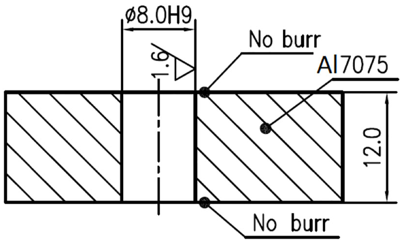
Technical requirements of hole.
Experiments for inner surface
Scheme of MAF
The scheme of the experiment for finishing inner surface of the hole by MAF process is shown in Figure 2.

Scheme of MAF for inner surface.
The working gap between the magnet and the inner surface was 1 mm with reference to the prior study. The MAPs scattered in the gap are in close contact with the workpiece surface under the constraint of the magnetic field. The MAPs form a flexible MAB, which is a machining tool in the MAF process. The relative movement is generated between the workpiece and the MAB while the magnet rotates. Due to the effects of magnetic force acting on the MAPs, a small amount of material was removed and a precise surface could be obtained by this process. The MAB is driven by the rotating magnet to continuously move on the surface, so that the entire workpiece can be finished.
Experimental design and parameter selection
According to the inductive analysis of the reference, the magnet spinning speed (r/min), abrasive size (mesh), and abrasive filling amount (g) were selected as the main objects of the study and are represented as
Each experimental parameter will take five levels if single experimental method was used, that is, 53 = 125 times if one material takes 125 times, which is a relatively large number and would be difficult to complete. Taguchi’s method is widely used for its advantages such as small number of experiments with high representation. It can distinguish the primary and secondary factors and analyze the experimental results through mathematical statistical method. Hence, Taguchi’s method was used in this article to evaluate the effect of process parameters on surface roughness, and the influence degree of each parameter was analyzed by ANOVA of the experimental data. And the optimal combination of process parameters will be found. The levels of parameters are shown in Table 2.
Parameters used in the experiment.

Comparison of radial and axial magnetic poles
As shown in Figure 3, both radial and axial magnetizing poles can be used in the MAF process for finishing the inner surface of the holes. The research results show that the distribution of magnetic induction density will directly affect the final finishing effect. Therefore, referring to the related literature and using ANSYS software, the simulation and analysis of induction density were performed. The simulation results (Figure 3(b) and (c)) show that the maximum magnetic induction intensity of the axial magnetic pole is 60% of the radial magnetic pole, and the ratio of the exit and entrance of the hole is smaller. In addition, as radial magnetic poles were used, the magnetic lines of force are more evenly distributed in the effective area of the inner wall. So, the radial magnetizing pole was adopted for the experimental study.

Comparison of radial and axial magnetizing pole: (a) pole appearance, (b) radial magnetizing, and (c) axial magnetizing.
Experimental device and conditions
The experimental device of MAF for finishing the holes is shown in Figure 4.

Experimental device of MAF.
A six-axis KUKA KR16 robot was used in the study to meet the needs of precision hole manufacturing in Al7075 structural parts in the production line. The magnet is clamped by collet and connected with the robot by a flange. The workpiece was fixed on the table by fixture. The offline program was imported from computer to the control device. The device manually adjusts the magnet to the starting position of the motion. Computer-controlled unit drives the magnet reciprocating in the axial direction, and adjustable speed motor drives the bevel gear connected by flexible shaft to realize the rotary motion of magnet. To guarantee the reliability and authenticity of the experimental data, the integrity of the tool and the uniform drilling process were used and the number of holes per drill bit does not exceed 20. After pre-processing, the inner surface of the hole was measured, and the surface roughness was about Ra = 2.5 μm. The total time of MAF for the inner surface of the hole is 6 min, and abrasives and finishing fluid are changed every 1 min. The surface roughness value of four positions evenly distributed on the inner surface is obtained using the professional roughness measuring instrument every time, and the average value was recorded as the experimental results. The experimental conditions of finishing the inner surface are shown in Table 3.
Experimental conditions for inner wall.

Experimental results and discussions
The inner diameter of the hole before and after was measured using a 422-006M three-point inner diameter micrometer. The measurement accuracy of this inner diameter micrometer is ±0.005 mm, and the diameter deviations are shown in Figure 5.
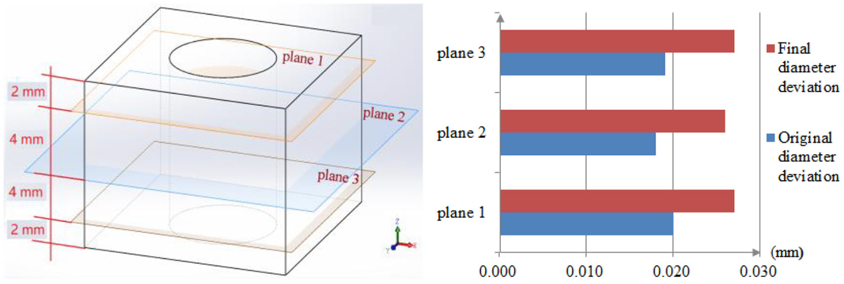
Diameter deviations of the hole.
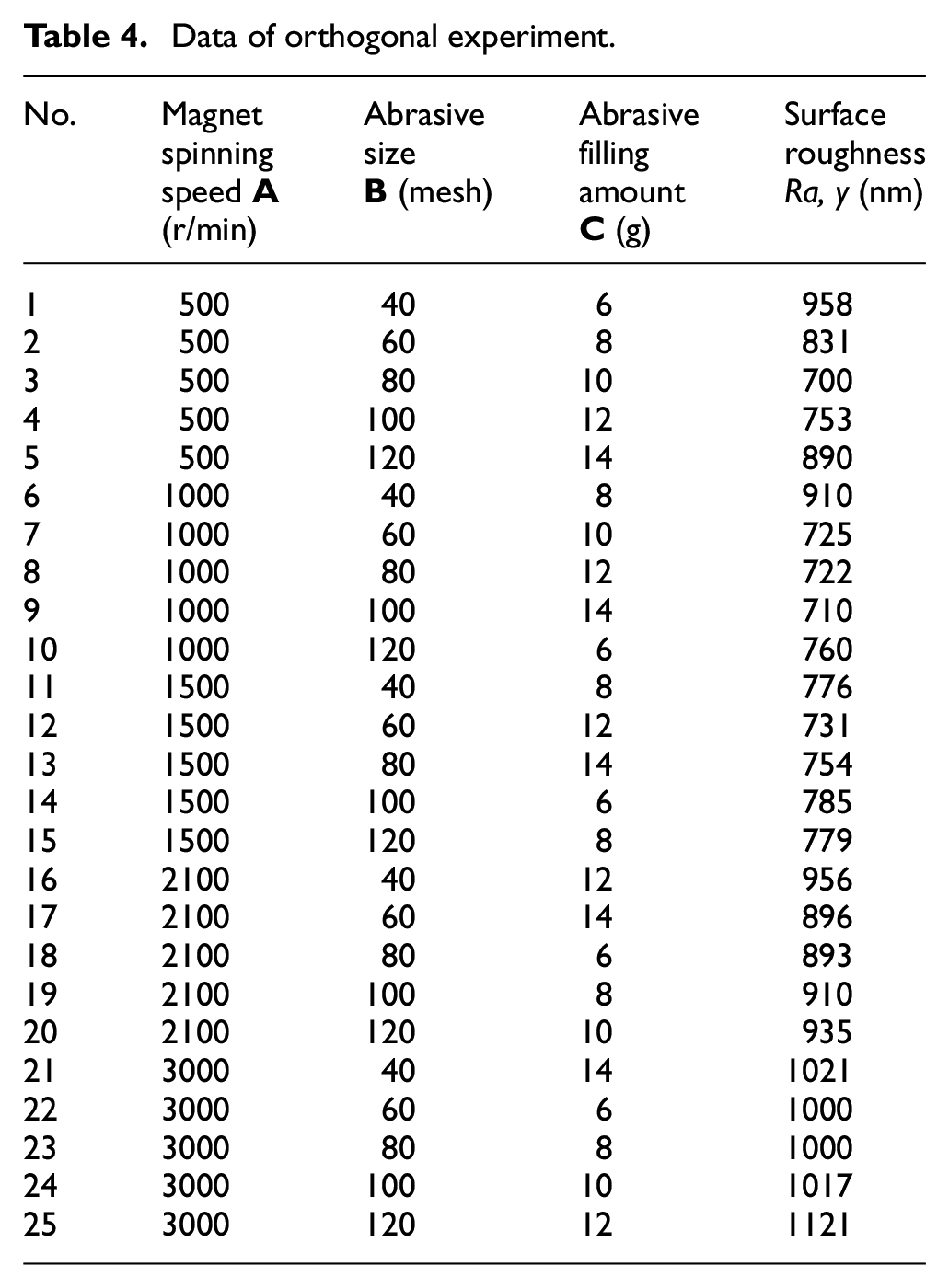
The diameter of the hole was measured at three locations: Plane 1, Plane 2, and Plane 3. The average value of diameter in the X-axis and Y-axis directions was measured, and the dimensional deviation was calculated. After the finishing process, the diameter deviations of the hole in the three measurement positions all increased, but the increase rate was small and still met the accuracy requirement of Φ8 mm H9 (0, 0.036 mm). The stylus surface roughness was measured by the SJ-210 instrument (Mitutoyo, Japan). As shown in Table 4, the decrease degree of surface roughness is different with the different process parameters. As a result, the value of the surface roughness of the inner surface of the hole reduced from Ra = 2.5 μm to about Ra = 0.7–1.0 μm.
Data of orthogonal experiment.
Effect of magnet spinning speed
The relationship between factors

Relationship between process parameters and surface roughness (Ra).
Effect of abrasive size
The surface roughness has a trend of decreasing first and then increasing with the increasing abrasive size (
Effect of abrasive filling amount
When abrasive filling amount (
Optimization analysis of process parameters
The main factors affecting the surface roughness can be found by the range analysis method of the orthogonal experimental data, and the optimal factor level combination can be found. According to the experimental data, ANOVA can be used to find out the factors that have a significant effect, and to find out how the level and process conditions can make the index optimal in order to achieve high quality and high efficiency. Table 5 shows the statistical analysis of orthogonal experimental data for finishing the inner surface of the Al7075 hole.
Statistical analysis of experimental data.

In Table 5, the “Ti” is the sum of the same level experimental indexes of “i” factor; “T” is the sum of experimental indexes which were corresponded by 25 experiments; “Xi” is the average value of same level experimental indexes of “i” factor; the total variation of measured value of 25 experiments consists of three factors of
Range analysis of experimental data.

ANOVA of experimental data.
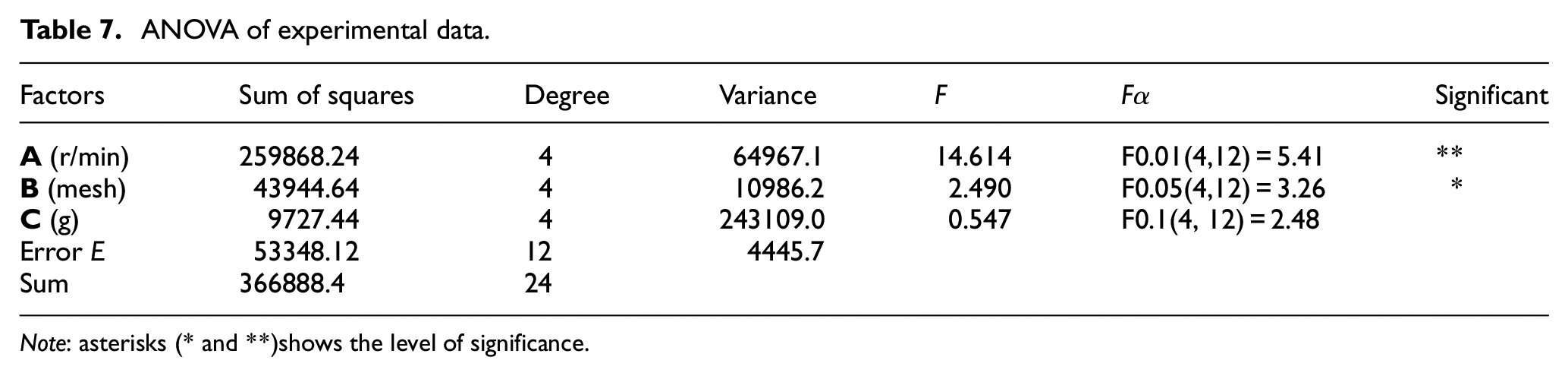
Note: asterisks (* and **)shows the level of significance.
Summarizing Tables 5–7, it can be seen that the important order of three parameters in the process of MAF for finishing the inner surface of the Al7075 hole is
Verification experiment
Based on the optimum process parameters of finishing inner surface of the Al7075 holes, the verification experiment was performed. The workpiece was cleaned with a PS-60AL ultrasonic cleaning machine (Shenzhen Shenhuatai Ultrasonic Cleaning Equipment Co., Ltd, China) and dried by hot air after finishing. The inner surface texture of the hole was measured using a VHX-500F ultra-depth field 3D electron microscope (KEYENCE, Japan), and the surface of the hole was measured with a SJ-210 stylus-type roughness profiler. Figure 7 shows the surface texture and the surface roughness R-curves of the inner wall before and after the MAF.

Surface morphology and surface roughness (Ra): (a) measuring position, (b) before finishing, and (c) after finishing.
Burr removal of the hole exit
It has been found that the burrs are produced when the cutting edge of drill bit comes in contact with the workpiece. Karnik et al. 18 claimed that burrs are formed in a circumferential direction as the drill bit is fed into the workpiece. These burrs are a source of dimensional errors and cause several problems to the parts’ function. They interfere with the assembly of parts, so jamming and misalignment occur. Burrs also pose reliability problems and interfere with machining sequence and assembly steps. The burrs produced on components lead to undesirable features such as improper contact between the current-carrying members and seating of the mating surfaces. Burrs are injurious during machining because they hit the cutting edge of the drill bit and cause groove wear. This groove wear, in turn, accelerates the burr growth. Ko et al. 19 and Deng et al. 20 indicated that burrs may reduce the fatigue life of components and act as a crack initiation point. Cho et al. 8 and Abele et al. 21 stated that the problem of exit burrs has been handled by developing secondary processes such as mechanical, electrochemical, abrasive jet machining, ultrasonic deburring, laser deburring, mechanized cutting, spot facing, and hand filing. As the exit burrs are formed on the intercross edge, burrs often flip into the hole in conventional burr removal process. There is no suitable process available for effective deburring, hence the new processes are in need. It was estimated that deburring and edge finishing may constitute as much as 30% of the cost of the finished parts, and the time used in deburring process for automatic machining operation accounts for 5%–10% of all machining time. The edge finishing and secondary finishing operations are difficult to automate and hence represent a bottleneck in a production line.
As a hole is drilled, there are burrs at the exit and entrance of the hole. The burrs of the hole entrance are small, and the inlet burr can be controlled to a usable range by optimizing the process parameters of the hole-making process and suitable drill pit. The burrs of hole exit appeared on the intercross edge of inner surface and exit surface. As the drill bit pierces the workpiece by pushing out uncut volume, the burrs are formed. The exit burr has a bad influence on ejection of chip, accuracy of final product, wear of drill bit, and surface roughness. In addition, burrs are a hindrance to all the succeeding processes. Therefore, it is essential to understand the formation mechanism of edge burrs in drilling process so as to minimize the burr size at the manufacturing stage. This necessitates suitable drill models describing the relation of burr size with each parameter and an efficient way for optimization.
In order to improve efficiency of burr removal of the hole exit, two novel plans were proposed. The basic principle is shown in Figure 8(a). In Plan 1, MAPs were constrained by a magnet with a diameter larger than the diameter of the hole, and the axis of the magnet coincides with the axial direction of the hole and maintains a certain clearance with exit surface. Due to magnetic revolution, magnetic field constrains MAPs to form MAB, and produce relative motion with burr, which was key fundamental to achieve the finishing process of edge burr. As shown in Figure 8(b), a magnet with a diameter larger than the hole was also used to constrain MAPs in Plan 2, but the axis of the pole was offset from the axis of the hole by a distance (eccentricity). When the magnet spins, it also rotates around the hole. The magnet spinning speed was n1 and the magnet around the axis of the hole revolution speed was n2. The main experimental parameters are shown in Table 8.

Principle of two kinds of burr removal process: (a) coaxial grinding and (b) eccentric grinding.
Experimental conditions for exit burr removal.

During the comparison test, the morphology of the burr was observed by digital microscope (VHX-500FE) every 1 min, and the height and width of the burr were also measured. The geometry of edge burrs of a hole exit before the MAF process is shown in Figure 9. Using the analysis software of the microscope, the measuring line was demarcated on the map, and the key points A, B, C, and D were specified. The distance of AB was the thickness of the burr (b), and the distance of CD was the height of the burr (h). So the values of b and h can characterize the appearance of the burr. By comparing the change of burr size during different grinding processes, it can be used to analyze the effect of burr removal.

Measurement for burr geometry.
Results and discussions
Comparison of burr size changes at the edge of the hole exit is shown in Figure 10. At the first 2 min of finishing process, the height and width of burrs decreased greatly, and burr removal efficiency was significantly higher than other stages. This was mainly due to the small volume and weak strength of the tip part of the burr, which meant that the removed weight was relatively small and easy to be removed. In addition, some burrs might part off, because the burr tips were coerced and oppressed, so the height of burrs decreased quickly. As finishing time increases, the removal efficiency of the burr thickness gradually reduced. The main reason is that as the height of the burr decreases, the width of the burr begins to increase, and the volume that the burr needs to remove also increases.

Changes comparison of burr size.
As the magnetic brush contacted with the flange and started lapping, part of the flanging fell off or was quickly removed, which made the burr thickness to drop rapidly. At the end of the finishing process, the burr removal efficiency of both the plans decreased.
According to the Princeton equation (1), the amount of material removal (M) was proportional to the grinding pressure (P) and the relative velocity (V); therefore, when the relative motion speed was constant, the lapping pressure would directly affect the amount of material removed and then the finishing efficiency was determined. Similarly, as shown in equation (2), the lapping pressure (P) was proportional to the square of the magnetic induction intensity (B). The magnetic induction intensity could improve the lapping pressure. When the height of the burr decreased, the clearance between the MAB and the burr increased, the magnetic induction intensity at the contact decreased, the lapping pressure (P) also decreased, and finally, the amount of material removal (M) decreased. The variation trend of the height and width of the burr was weaker than that of the initial stage. In addition, the contact between the bottom of the burr and the substrate was relatively firm, and the burr removal mechanism was mainly based on the gradual grinding at this time. The burr appeared partly in the process of grinding, so the removal efficiency was lower than the original stage

where k is constant, P is the lapping pressure (Pa), V is the relative velocity of motion (m/s), and T is the finishing time (s). And we have
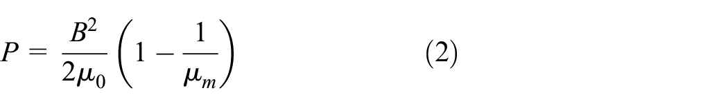
where B is the magnetic induction intensity at the action surface (T),
The finishing efficiency of Plan 2 was significantly higher than that of Plan 1 as shown in Figure 10. The deburring mechanism analysis of both the plans is shown in Figure 11.

Deburring mechanism analysis: (a) coaxial grinding and (b) eccentric grinding.
In Plan 1, as shown in Figure 11(a), the MAB formed by the bound MAPs coincides with the axis of the hole, and the MAB contacted with the burr of the whole hole. Taking a burr for force analysis, the MAB has two main forces on the burr,
Figure 11(a) also shows that the force exerted on the burr had no component force in the normal direction of the hole, and the burr may only be inclined along the tangential direction of the hole, but other burrs in the tangential direction will support the burr, which weakens the tendency of the burr to tilt, thereby making the burr fracture probability to drop. When the magnet spinning speed is constant, the value of
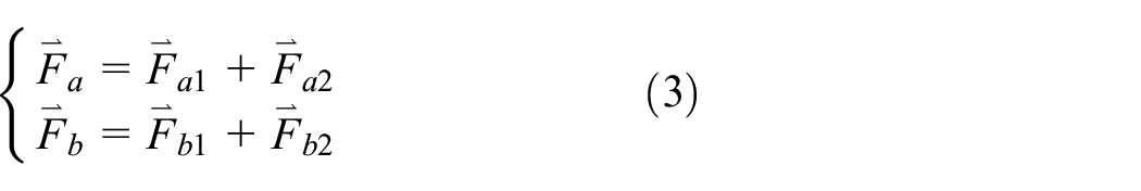
where
The machining trajectory of the two plans combined with equation (4) is shown in Figure 12

where x is the horizontal processing distance (mm), y is the longitudinal processing distance, (mm), r1 is the distance from the machining point to the hole center (mm), r2 is the distance from the processing point to the center of the magnetic pole (mm), and t is the processing time (s).

Grinding trajectory in two plans: (a) conventional trajectory and (b) improved trajectory.
In Figure 12(a), magnetic particles only ground the workpiece when the magnetic pole rotates. This processing method is relatively simple, so the trajectories are similar to parallel circles. In Figure 12(b), magnetic particles revolved around the center of the hole while rotating with the magnetic pole. This processing method complicates the machining trajectory.
During the whole finishing process, the PP and QQ areas are in contact with MAB, and also constantly move along with the edge of the hole due to the influence of magnet revolutional speed n1. In Figure 12(a), the direction of the resultant force of acting on the burr at a certain position always alternates along the normal direction of the hole toward the inside or the outside. The strength and stiffness of the burr are lower in the normal direction than in the tangential direction. Burrs were more easily deformed at this time. Larger alternating load would accelerate the fatigue shedding of burrs, and thus the finishing efficiency was greatly improved, and the burr height and width decreased rapidly. Improved trajectory grinding is more advantageous, which is consistent with the results of the force analysis.
When the finishing time reached 6 min as shown in Figure 12(a), all the burrs of the hole exit had almost been removed, while the burr removal takes only 5 min by Plan 2. Based on Figure 12(b), the size of edge burrs was measured 4 min after finishing and compared with the original topography. The results are shown in Table 9.
Comparative morphology before and after burr removal process of Plan 2.

After 4 min of grinding based on Plan 2, the burr at the edge of the hole exit was significantly removed. After the burr was removed, no obvious rounded corners were seen at the edge of the hole, and the cuts and spots on the peripheral surface of the hole edge were almost completely removed. No obvious texture morphology was seen on the microscopic y surface, and the surface quality was significantly improved. The burr removal efficiency increased by 33.3% by improved trajectory compared with conventional MAF process.
Conclusion
In this article, the MAF process was proposed to finish the inner surface of Al7075 holes and to remove edge burrs of hole exit. The magnetic pole type was compared by simulation analysis to finish the inner surface. The impact factor of three typical parameters was studied by Taguchi’s method and the best parameter combination was obtained according to the analysis of range and ANOVA, which were verified experimentally. Two plans were proposed to remove the edge burrs and a comparative analysis was performed. Some main conclusions are drawn as follows:
As the inner surface of the hole is finished by the MAF process, the radially magnetized magnet has more advantages than the axially magnetized magnet;
After the finishing process, the diameter deviations of the hole increased, but the Φ8-mm hole still met the accuracy requirement of H9 (0, 0.036 mm).
The magnet spinning speed is more significant than the two other parameters for finishing the Al7075 inner surface. The best parameter combination was obtained: the magnet spinning speed is 1500 r/min, the abrasive mesh is 80, and the filling amount is 10 g.
The edge burrs of the Al7075 hole exit can be removed efficiently under the obtained conditions: magnet spinning speed is 1500 r/min, magnet revolution speed is 200 r/min, and eccentric distance is 4 mm, by which the burr removal efficiency is improved by 33.3% compared with the conventional MAF process.
Footnotes
Handling Editor: James Baldwin
Declaration of conflicting interests
The author(s) declared no potential conflicts of interest with respect to the research, authorship, and/or publication of this article.
Funding
The author(s) disclosed receipt of the following financial support for the research, authorship, and/or publication of this article: The study was supported by “High-end CNC machine tools and basic manufacturing equipment” of the National Major Science and Technology Project Grants (no. 2016ZX04002005), China. It was also supported by the Natural Science Foundation of Liaoning Province Grant (no. 2019-ZD-0029) and the University of Science and Technology Liaoning Talent Project Grants (no. 601011507-32).