
Abstract
When a thin film bonded to a thick compliant substrate is subject to in-plane compression, wrinkles can develop if the critical state for instability is reached. In various applications the film/substrate system may also take the form of cylindrical fibers, where an axial compressive loading can trigger axisymmetric wrinkles. A straightforward computational approach to simulate such wrinkling behavior is needed for material design, to either prevent wrinkling or to exploit its benefits for flexible device applications. In this work a comprehensive numerical study is undertaken by employing the finite element method. The embedded imperfection approach used previously for planar structures is now applied to the cylindrical film/substrate system to trigger axisymmetric wrinkles. Uniform and reversible elastic wrinkles can be directly predicted, and the wrinkle geometries are verified by available elastic analytical solutions. The effect of initial imperfection location is also examined. We further study plastic yielding and viscoelasticity of the thin film, and examine how the wrinkle configuration may be influenced by inelastic deformation. Yielding transforms the uniform wrinkles into localized deep folds, and this new surface feature is irrecoverable upon unloading. A viscoelastic thin film results in rate-dependent instability behavior, with very slow strain rates favoring localized waveforms. This study has developed a robust computational approach for the prediction of wrinkle initiation and growth in cylindrical structures with a thin film bonded to a soft core. It is demonstrated that material nonlinearity and rate dependency can be incorporated into the model to greatly expand the simulation capabilities.
Introduction
This study concerns cylindrical fiber-like structures with a thin outer layer (film) bonded to a compliant core (substrate) under axial compression loading, where buckling instability triggers the formation of periodic wrinkles on the thin film. While a wrinkled surface is frequently deemed undesirable, it is increasingly exploited for enhancing certain functionalities.1–4 For instance, organic semiconducting films such as P3HT:PCBM (poly(3-hexylthiophene): phenyl-C61-butyric acid methyl ester) exhibit superior flexibility, tunable optoelectronic properties, and enhanced environmental stability, ideal for wearable electronics and flexible photovoltaics. Optimized through thermal annealing and electron transport layers, these films achieve balanced charge transport, efficient charge separation, and high-power conversion efficiencies.5–8 A wrinkled optoelectronic film may exhibit improved energy conversion and mechanical resilience. The film/substrate structure can be made into the cylindrical fibrous form which may be utilized as a basic component in flexible optoelectronic fabrics.
Thin-walled cylindrical shells have historically found many applications in rockets, missiles, aircraft fuselage, submarine body, and pressure vessels. Their pattern of deformation under axial load is of importance for efficient design and safe operation. The axial compression buckling of shell-like structures has been extensively studied. The buckling of a hollowed cylindrical shell was treated in the classic book by Timoshenko and Gere. 9 To gain a complete understanding of the buckling behavior of cylindrical shells, extensive theoretical studies have been conducted by numerous researchers, encompassing analytical solutions, numerical simulations, and stability analyses.10–16 Aside from these theoretical attempts, several experimental investigations have also been reported, providing valuable information on practical buckling behavior as well as validating theoretical predictions. 17
Karam and Gibson 18 investigated the elastic buckling of a thin cylindrical surface reinforced with an elastic core, which resulted in weight reductions over a hollow cylinder. Agarwal and Sobel 19 compared the weights of optimally stiffened, unstiffened, and sandwiched cylindrical shells, finding that honeycomb sandwiched cylindrical shells outweighed axially stiffened cylinders under compression in the axial direction. Hutchinson and He 20 examined the buckling of cylindrical shells with metallic foam cores under axial stress, and discovered that optimized sandwich structures with metallic foam cores may offer a significant weight benefit over metal stringer designs. Their results also revealed high sensitivity to imperfections as in monocoque cylinders. Arani et al. 21 used the energy technique to evaluate the elastic stability of cylindrical shells containing an elastic core undergoing axial compression. They determined that adding an elastic core enhanced elastic stability, thus substantially lowering the weight of cylindrical shells. Bradford et al. 22 investigated the use of concrete infill in hollow circular steel columns for high-rise buildings.
There have been studies treating the multi-walled carbon nanotubes as concentric shell structures with Van der Waals interactions between the walls.23,24 Some researchers have addressed the buckling of a filled single-walled shell.25,26 Several studies have modeled multi-walled carbon nanotubes as nested cylindrical shells, considering the Van der Waals interactions between adjacent concentric layers.23,24 Additionally, researchers have explored the buckling behavior of single-walled cylindrical shells containing internal fillers, investigating how the presence of these fillers influences the structural stability and mechanical performance of the nanotube structures.25,26 Ye et al. 27 investigated the effect of partially filled foam cores on the buckling of thin-walled cylindrical shells, which demonstrated that the filling of a foam core enhanced the buckling resistance. Further investigations have targeted the stabilizing effect of low-modulus cores in isotropic shells. Wu et al. 28 studied the axial compression buckling behavior of soft material-filled, concentric multi-walled cylindrical shells. Their findings revealed that when the bulk modulus of the filled materials is comparable to (or greater than) the Young’s modulus of the shell, the axial compression resistance improves significantly during the post-buckling phase.
A relatively recent work by Zhao et al. 29 explored the impact of film thickness and substrate stiffness on the onset of buckling, substantially expanding the parameter space for cylindrical film/substrate systems considered previously. Several types of imperfection-based numerical approaches have been used to investigate surface instability in planar structures.30–36 However, their implementation frequently involves calibrating several free parameters, and the interpretation and verification of results may not be straightforward. To overcome the challenges, Nikravesh et al.37–39 have developed a modeling technique that predicts the onset and temporal evolution of surface wrinkles in a seamless way. It is based on embedded defects at the film-substrate interface. In their finite element model, one or more elements in the substrate material immediately below the thin film are assigned the thin-film material’s properties instead of the substrate’s. Conceptually, this may be regarded as having a non-perfectly flat interface, which is unavoidable in real physical systems. The simulation approach has been verified using known experimentally validated analytical solutions of wrinkle wavelength, amplitude, and critical buckling strain, under the premise of small-strain linear elasticity and perfect bonding at the film-substrate interface. This modeling approach was shown to be able to predict wrinkling progression from the initial state to several bifurcations (pattern changes) in a single simulation session. Simple sinusoidal waveforms and complex three-dimensional surface patterns as well as their transitions can be directly simulated.40,41 This embedded imperfection technique serves as the basis in the present study.
The primary objectives of this work are: (i) to employ the aforementioned embedded imperfection modeling framework in the axisymmetric thin film/compliant substrate system, and study its feasibility, (ii) to perform model verification based on available elastic analytical solutions, (iii) to extend the analysis to inelastic thin films and examine how plastic yielding and viscoelastic deformation will affect the formation and transformation of wrinkles on the cylindrical surface.
In the remainder of this article, the numerical model description is first presented. A brief summary of relevant elastic theories of cylindrical wrinkling then follows. In subsequent sections we first present model verification, effects of initial defect location, and loading-unloading response using elastic analyses. Plastic yielding of the thin film is then investigated, which also includes the effects of yield strength and imperfection location. The study of viscoelastic thin films then focuses on how different loading rates will influence the wrinkle pattern. Important findings are summarized in the “Conclusions” section.
Methodology
Figure 1 shows the schematic of the numerical model which is a cylindrical segment of length L and radius R, with the outer skin being the thin film of thickness h perfectly bonded to an inner core (substrate). Due to axial symmetry, the R × L rectangular domain is needed for the axisymmetric simulations. During loading, a uniform increasing downward displacement is applied quasi-statically on the top boundary, while the bottom boundary remains in position although tangential sliding is allowed. The left boundary is the symmetrical axis, and the right boundary (film surface) is unconstrained. The total load is then the reaction force along the loading direction summed over the boundary nodal points where the displacement is applied. To trigger film buckling, a regular finite element in the substrate adjacent to the thin film at the middle height is chosen as the imperfection, which carries the thin film material properties instead of the substrate. Note that previous studies on flat elastic structures have considered single versus multiple random imperfections, and the validity of using one imperfection was confirmed.37–39 In the current study of the cylindrical system, we started with the baseline elastic case with one imperfection. The simulation domain considered may thus be viewed as a representative unit segment of a long periodic cylindrical structure along the y-axis. To investigate the effect of embedded imperfection for inelastic thin films, we also consider imperfections at other vertical locations along the interface.

Schematic of the cylindrical thin film and substrate (core) model. The actual computational domain is the highlighted two-dimensional rectangle due to axial symmetry.
Unless otherwise stated, the model dimensions are taken as L = 93.58 µm, R = 27.96 µm, and h = 0.1 µm. The film thickness is the same as in our previous work on flat film/substrate structures.37–39 While the choice of dimensions is arbitrary, it is guided by the theoretical wavelength so the model is expected to accommodate a sufficient number of waves. Furthermore, the substrate thickness (radius) is much greater than the film thickness, including the cases in the parametric study of film thickness effect presented in the following section. Note that the model dimensions can be scaled up or down without altering the simulated wrinkle features. The substrate material is treated as isotropic linear-elastic and nearly incompressible, with Young’s modulus E s = 2.97 MPa and Poisson’s ratio ν s = 0.495. The elastic properties correspond to those of PDMS (polydimethylsiloxane). 42
The thin-film material is assumed to be isotropic linear-elastic, with Young’s modulus E f = 7300 MPa and Poisson’s ratio ν f = 0.35. Some other modulus values are also used for model verification. The pure elastic film/substrate system will lead to periodic wrinkles and will be compared with analytical solutions for model verification as presented below. In this work we further treat the thin film as an elastic-perfectly plastic solid, to study if and how plasticity will dictate the instability morphology. The plastic yield strength considered is in the range between 25 and 70 MPa. The material characteristics resembles those of typical organic semiconductor films of P3HT:PCBM (poly(3-hexylthiophene): phenyl-C61-butyric acid methyl ester) in flexible optoelectronics.43,44 To examine the possible loading rate effect on the cylindrical wrinkling behavior, a viscoelastic thin film is also considered. The detailed viscoelastic properties are described in Section “Effects of viscoelastic behavior.”
Numerical simulations were conducted using the commercial finite element program ABAQUS (Version 2022, VIAS3D Academia, Houston, TX, USA). Four-noded quadrilateral axisymmetric continuum elements are used throughout. Various degrees of mesh refinement were tested to ensure convergence. The mesh density is higher within the film and near the interface region, with four layers of elements across the film thickness. In the substrate the element size gradually increases from the interface to the inner region. The results presented in this work are based on a total of 40,000 elements in the model. Note that in the actual cylindrical film/substrate system under axial compression, wrinkles may form in both the axial and circumferential directions, the latter of which requires full three-dimensional modeling while the former is amenable to axisymmetric modeling. The actual wrinkling form depends on the modulus ratio E f /E s and thickness ratio h/R, with relatively low E f /E s and h/R favoring axisymmetric wrinkles. 29 In the current study, the material and geometric parameters listed above are within the axisymmetric thresholds.
Relevant elastic analytical solutions to be used for verifying the axisymmetric numerical models are now presented. A premise for the theoretical treatment is

where


These analytical expressions have also been validated by experiments using a cylindrical PDMS core with a thin outside coating of high-density polyethylene. 29 Numerical results obtained from the current study will be compared with these quantities in the following section.
It is noted that the present numerical model focuses only on finite-element based mechanical simulations of deformation instabilities. Other influences such as micro-strain, thermal extinction coefficient and lattice mismatch are not included in the consideration.47–51
Model verification and elastic simulations
Figure 2(a) shows the variation of critical wrinkle wavelength with the mesh density, represented by the number of surface-layer elements per wave, obtained from the numerical modeling. A simulated periodic wrinkle configuration is shown as an inset. Figure 2(a) also includes the analytical solution, obtained from equations (1) and (3), as a horizontal line. It is clear that the numerical results deviate from the theoretical λ cr value if the model uses fewer elements, but convergence is achieved when the mesh is sufficiently fine. Figure 2(b) shows the critical compressive stress in the thin film as a function of mesh density. The analytical solution based on equations (1) and (2) are included as the horizontal line. As in the case of wrinkle wavelength, the critical stress to cause instability obtained from the simulations also coincides with the theoretical value if sufficiently fine elements are used. All subsequent numerical results presented in this paper are based on the finest mesh considered in Figure 2.

Variation of the simulated (a) wrinkle wavelength and (b) critical compressive stress in the thin film, with the number of elements per wavelength. The analytical solutions are also included for comparison. The simulated wrinkle configuration is shown as an inset in (a); in this image and all the others showing wrinkles, a deformation amplification factor is utilized for the post-processed images to make the waveform more evident.
Figure 3 shows the evolution of wrinkle amplitude, defined to be one half of the distance in the radial direction between the peak and valley points, as the applied compressive strain increases. A range of Young’s modulus of the thin film is considered, with the middle 7300 MPa being the “standard” value used in this study. The film surface remains straight (zero amplitude) prior to instability; upon reaching the critical point wrinkles quickly take shape. A higher film modulus signifies a greater extent of stiffness mismatch between the film and substrate, which leads to earlier onset of instability as observed in Figure 3. From equations (1) to (3), both the wavelength and critical film stress are functions of film modulus so they can be directly compared with the current simulations, as shown in Figure 4. Here the substrate modulus in all cases is kept constant, and the variation of film modulus is presented as the modulus ratio (E f /E s ). It is evident that the finite element modeling results are generally consistent with the theoretical values for the wrinkle wavelength (Figure 4(a)) and critical film stress (Figure 4(b)). Although in Figure 3 a higher film modulus corresponds to a smaller critical strain, the critical stress in Figure 4(b) is in fact greater, due to the higher stiffness of the thin film.

Evolution of elastic wrinkle amplitudes as a function of applied compressive strain obtained from the simulations. A range of Youngs’ modulus of the thin-film material is included.

Variations of the simulated (a) wavelength and (b) critical film stress, with the modulus ratio (E f /E s ). Analytical solutions are also included for comparison.
Figure 5(a) and (b) show the variations of wavelength and critical film stress, respectively, as a function of the thickness ratio (h/R). The standard E f and R values are used, and several film thickness values (in addition to the standard h = 0.1 µm) are considered. The analytical solutions are also included in the figures for comparison. It can be seen that a thinner film leads to a smaller wavelength and a smaller critical film stress to trigger instability. The simulation results are in good agreement with the theoretical values.

Variations of the simulated (a) wavelength and (b) critical film stress, with the thickness ratio (h/R). Analytical solutions are also included for comparison.
As described in Section “Methodology,” the embedded imperfection is a regular finite element by the interface inside the substrate carrying the properties of the thin film. (Without the imperfection, the deformed cylindrical structure will remain straight under axial compression.) If the imperfection is placed at a different vertical position (upward or downward, away from the mid-height in Figure 1), the resulting wrinkle pattern (including the wavelength, amplitude, and overall configuration) is unaffected according to our preliminary analyses. This manifests the generality of the present approach in elastic analysis. Note that a different way of placing the imperfection may be attempted, as depicted in Figure 6. Here the imperfection was placed inside the thin film by the interface, and it carries the properties of the substrate material. The resulting wrinkle configuration has the same wavelength and amplitude as seen in Figure 6, with a total number of waves of 20. However, in the original case (imperfection in substrate) the top and bottom edges of the film are the valley points of the waves, but the new imperfection location leads to peaks at these two edges. In other words, at the same vertical level of the imperfection, the wrinkled film is at the valley point and peak point for the original and new cases, respectively. Aside from the flipped shape, all geometric features of the wrinkles stay unchanged. The flipped shape may be a consequence of the different strain concentration around the imperfection. It may also be influenced by the local interface geometry in the model, that is, depression into the substrate (original) versus protrusion into the film (new).

Wrinkle patterns resulting from the placement and properties of the imperfection.
Figure 7 shows a representative load-strain curve during compressive loading and unloading back to the origin, obtained from the simulation. Some snapshots showing the deformed configurations are included as insets in the figure. Note that only the elastic material behavior is considered. The initial linear segment is thus the regular elastic response of the film/substrate cylindrical composite. Instability commences when the compressive strain reaches about 0.0047 (which corresponds to the critical buckling film stress of 32.68 MPa), and an abrupt change of the slope is evident. Wrinkles start to appear from this critical state. Upon unloading, the amplitude of these wrinkles decreases gradually, and the unloading response follows the loading path in a reversed manner. Wrinkles vanish at the same critical strain. Afterward the composite continues to unload following the initial elastic load-strain path. At the end there is no residual deformation, and the stress is reduced back to zero. This reversible form of deformation instability is consistent with that of the planar thin film/thick substrate structure observed in a previous simulation study. 52

Load-strain history along with some deformation snapshots. Both the loading and unloading phases are included (they follow the same path).
Effects of thin film plasticity
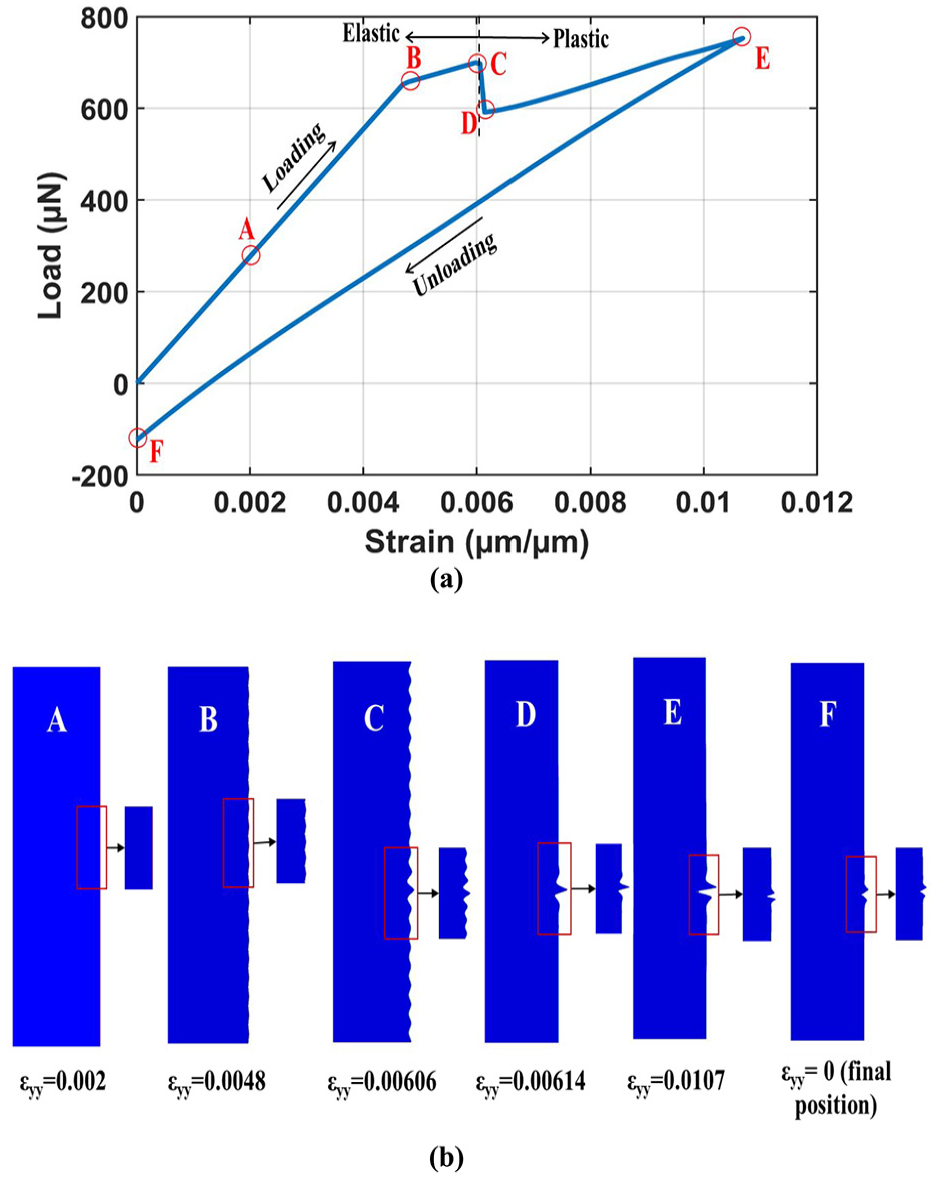
We now consider the deformation history and evolution of wrinkle patterns if plastic deformation occurs in the thin film. The thin film material is assumed to be elastic-perfectly plastic, with the yield strength varied between 25 and 70 MPa. All the other modeling parameters remain unchanged. Figure 8(a) shows the simulated load-strain curves during loading and unloading, when the yield strength is taken as 70 MPa. Figure 8(b) show the deformation snapshots at some key points labeled along the load/unload history in Figure 8(a). The initial linear segment is the pre-instability elastic response, the same as in Figure 7. At point B, wrinkles start to form while the thin film is still elastic. At C, plastic yielding commences and there is a sudden reduction in load. Initial wrinkles largely disappear, but near the imperfection site local wrinkles evolve into a tall ridge (point D) which gradually turns into a deep fold at point E. Upon unloading, the plastic fold becomes shallower, but it remains in place. Note that the unloading curve does not follow the initial path, and residual deformation exits at the end.

(a) Load-total strain curve during loading and unloading, when the yield strength of the thin film is 70 MPa. (b) Snapshots showing the wrinkle patterns corresponding to the various stages of deformation labeled in (a). The symbol εyy represents the applied compressive strain.
The results shown in Figure 8 are for the case where plastic yield strength of the thin film is higher than the critical stress to form elastic wrinkles. We now consider an opposite case where yielding occurs earlier than elastic instability. Figure 9(a) shows the simulated load-strain curves during loading and unloading, when the yield strength is 25 MPa. Several deformed configurations corresponding to the points labeled along the load-strain history are shown in Figure 9(b). The abrupt load drop from points A to B is caused by yielding, which also triggers immediate plastic wrinkle formation. Note that there is no periodic waveform but only a tall ridge with flanking valleys at the imperfection site. As compressive straining continues, the localized pattern evolves into a deep fold (point C) similar to that observed in Figure 8. Residual surface disturbance exists at the end of unloading.

(a) Load-total strain curve during loading and unloading, when the yield strength of the thin film is 25 MPa. (b) Snapshots showing the wrinkle patterns corresponding to the various stages of deformation labeled in (a). The symbol εyy represents the applied compressive strain.
Figure 10 shows the comparison of load-strain curves which include two additional yield strengths: 40 and 55 MPa. During loading, the load-carrying capability increases as the yield strength increases. In the case of 40 MPa yield strength, elastic wrinkle formation coincides with plastic yielding (at strain 0.0047). Therefore, yield strength greater than 40 MPa results in a segment of post-instability elastic response prior to the yielding-induced load reduction. The cylinder with the lowest thin-film yield strength displays the greatest residual deformation after unloading. In flexible device applications, a common rationale to create a wrinkled surface is to enhance mechanical resilience during subsequent tensile loading (to delay cracking) since the initial wrinkles will need to be flattened first. However, one also needs to ensure that any plasticity-induced residual fold will not become a stress raiser which may promote early damage.
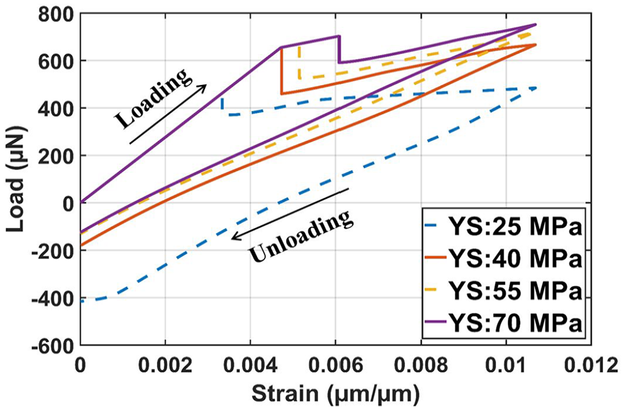
Load-strain curves during loading and unloading, for the thin-film yield strengths (YS) of 25, 40, 55, and 70 MPa.
To examine the effect of pre-existing imperfection on the plastic wrinkling behavior, we also carried out simulations using a model with two imperfections and the thin-film yield strength of 70 MPa. The load-strain history and representative deformation snapshots are presented in Figure 11(a) and (b), respectively. One imperfection is in the middle-height position as before, and the other is at a lower position (where the final remaining wrinkle is located). The load-strain curve looks similar to that in Figure 8(a) with the same yield strength. A notable difference is the load reduction associated with yielding-triggered wrinkle transition – the one in Figure 11(a) is not as abrupt as in Figure 8(a). There appears to be a “competition” of the wrinkle transition process at the two imperfection sites, and one eventually prevails (the lower one). This is believed to result in a comparatively smoother load drop in Figure 11(a). The final plastic fold patterns for the two cases, however, are qualitatively the same. The residual profiles at the end of unloading are also similar. It is unclear why the final plastic fold appears at the lower imperfection site in Figure 11. A future systematic study may be needed. We also conducted several simulations placing one imperfection in the substrate and the other in the film. In all cases the results exhibited the same wrinkle pattern and overall deformation behavior.
(a) Load-strain curve during loading and unloading, when the yield strength of the thin film is 70 MPa and the model contains two imperfections. (b) Snapshots showing the wrinkle patterns corresponding to the various stages of deformation labeled in (a).
In Figures 8 to 11 it was observed that plastic yielding of the thin film triggers wrinkle formation (or wrinkle transition, depending on the yield strength) and causes sudden load reduction. To further demonstrate the critical role played by the embedded imperfection, we compare the load-strain curves resulting from models with and without the imperfection, as shown in Figure 12. Here the yield strength is taken as 25 MPa. It is evident that, without imperfection, a simple elastic-plastic response is obtained. (Although a perfectly plastic behavior is specified for the film material upon yielding, the plastic part of the curve displays a slight upward trend because the cylindrical core is still a pure elastic material.) With the existence of an imperfection, yielding immediately triggers instability, and the localized surface pattern is shown in Figure 9(b). While the thin film has a uniform elastic-perfectly plastic behavior throughout, the existence of imperfection forces the evolution of plastic fold in a localized manner.

Comparison of the load-strain curves obtained from models with and without the imperfection. The yield strength of the thin film is 25 MPa.
Effects of viscoelastic behavior
To further explore how the constitutive behavior may affect wrinkling configuration, we consider the viscoelastic thin film in this section. A straightforward three-element conventional linear solid model is adopted, as schematically shown in Figure 13. The dashpot viscosity, unrelaxed (instantaneous) shear modulus, and fully relaxed shear modulus are represented by the symbols η, G u , and G r , respectively. Their values in this particular investigation are η = 24,336 MPa s, G u = 2704 MPa, and G r = 270.4 MPa. The time-dependent response in the context of linear viscoelasticity may be described as the shear modulus’ relaxation behavior,

where t is time and

The three-element standard linear solid model used for the viscoelastic film.
With the viscoelastic thin film, deformation becomes rate dependent. Different compressive strain rates between 0.001 and 0.00025 s−1 are considered in the simulations. Figure 14(a) shows their load-strain curves, along with the curve for the case of pure elastic (rate-independent) film. Note that the pure elastic curve is the same as that in Figure 7, and its change in slope is associated with the formation of uniform wrinkles. For models with the viscoelastic thin film, a higher strain rate leads to a load-strain response closer to the pure elastic case. A slower deformation rate results in a more relaxed state.
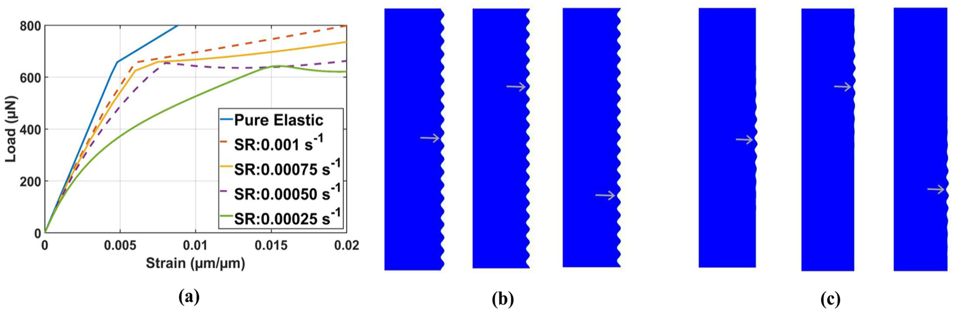
(a) Load-strain curves obtained from different applied strain rates in the simulations, when the thin film is assumed to be viscoelastic. (b) Representative wrinkle patterns at compressive strain of 0.02 when the applied strain rate is (b) 0.00075 s−1 and (c) 0.00025 s−1. In (b) and (c), three separate cases of imperfection location are included, as highlighted by arrows.
Representative wrinkle patterns are shown in Figure 14(b) and (c), for the applied strain rates of 0.00075 and 0.00025 s−1, respectively. We also explored different imperfection locations, three of which are shown in Figure 14(b) and (c) as indicated by the arrows. Uniform wrinkles throughout the axial span of the film, as in the pure elastic case, are observed for strain rates at 0.0005 s−1 and higher (Figure 14(b) is among this group of higher strain rates). Note also that the uniform wrinkle patterns are not influenced by the location of the imperfection, except for the flipped shape in Figure 14(b) when the imperfection position is adjusted. The flipped shape may be due to the mutual influence between the model size and the relative position of the imperfection, since the top and bottom edges of the model are both symmetry planes and a certain number of full waves need to be accommodated between the two boundaries. At slower applied strain rates, Figure 14(c), however, wrinkles become localized near the initial imperfection site. Not shown in this paper is that, when the applied strain rate is extremely slow, no wrinkle will form within a reasonable range of applied strain. This is due to the heavy relaxation such that the stress experienced by the film remains below the critical value for instability.
The numerical results presented in this paper illustrate that the constitutive behavior of the thin film plays a decisive role in the wrinkling configuration. The present embedded imperfection technique provides a robust means to simulate the formation and transformation of axisymmetric wrinkles in the cylindrical film/core structures. Future studies may involve 3D simulations to study non-axisymmetric surface morphologies on the cylindrical surface.
Conclusions
A comprehensive numerical study using the finite element method was conducted, for wrinkling instabilities on thin films attached to a compliant cylindrical substrate. The embedded imperfection approach used previously for planar structures was employed to trigger the axisymmetric wrinkles. The computational models were verified by available analytical solutions in the pure elastic state. Other key findings are summarized below.
- Reversible deformation history in the pure elastic model can be directly simulated. An elastically wrinkled state is reverted to the straight cylindrical shape upon unloading.
- The imperfection placed on the opposite side of the interface leads to a flipped waveform, but the wave’s geometric features otherwise remain unchanged.
- Plastic yielding of the thin film causes an abrupt reduction in the overall load and significantly affects the wrinkle configuration. If uniform elastic wrinkles are already formed, yielding leads to localization of the surface pattern and turns it into a deep fold at the imperfection site. If yielding occurs earlier than the critical elastic instability, a localized plastic fold will form directly. The plastic fold remains in place after complete unloading.
- When the viscoelastic behavior of the thin film is considered, the overall load-strain response and the wrinkle pattern become rate-dependent. A faster loading rate generates uniform wrinkles similar to the pure elastic case, while a slow rate may induce waveforms only around the imperfection site.
- This study illustrated the versatility of the embedded imperfection technique in modeling wrinkling instabilities for the axisymmetric film/substrate system. Future studies may include the full 3D model so a wider range of parameters can be considered, for simulating the formation and transformation of possible non-axisymmetric wrinkle patters on the cylindrical surface.
Footnotes
Handling Editor: Sharmili Pandian
Author contributions
MARA and Y-LS conceived the idea for the research and contributed writing the first draft. MARA performed the numerical simulations directed by Y-LS. DR provided guidance on the physical behavior of materials. All authors collaborated on finalizing the manuscript.
Funding
The author(s) disclosed receipt of the following financial support for the research, authorship, and/or publication of this article: The authors would like to acknowledge NASA EPSCoR CAN (grant #: 80NSSC23M0069) for supporting this study. Y-LS further acknowledges the endowment support from PNM Resources Foundation.
Declaration of conflicting interests
The author(s) declared no potential conflicts of interest with respect to the research, authorship, and/or publication of this article.
Data availability statement
The datasets generated and analyzed during the current study are available from the corresponding author on reasonable request.