
Abstract
Surface buckling (wrinkling) driven by mechanical instability is commonly observed in thin-film structures with a compliant substrate. The resulting undulation, while sometimes undesirable, has been increasingly exploited to enhance mechanical and/or functional performances of many thin film devices. In this study a practical finite element modeling approach is introduced to simulate wrinkle formation in thin films atop a compliant substrate. The proposed technique is robust and easy to implement, and it overcomes typical challenges in computationally modeling the buckling instability. Using a two-dimensional geometry under the plane strain or generalized plane strain conditions, with randomly distributed imperfections bearing different material properties at the film/substrate interface, we demonstrate the model’s capability in triggering surface instability during direct compression and out-of-plane tensile loading. With sufficient mesh refinement, the predicted wrinkling wavelength, amplitude, and critical strain to activate wrinkle formation are shown to be close to analytical solutions. The effect of imperfection distribution is systematically studied, and a valid range of imperfection spacing is identified. The present numerical approach can be applied to predicting buckling instability in the design and analysis of thin film/compliant substrate systems over a wide range of material and geometric conditions. Directions for future studies are also discussed.
Introduction
Formation of buckles (wrinkles) on a thin film attached to a compliant substrate has received considerable attention due to the advancement of flexible electronics,1–5 optoelectronics and photovoltaics,6–11 and various functional devices,12–16 as well as the development of self-organizing mechanisms.17–21 Buckling can be triggered by direct application of an in-plane compressive strain, as schematically shown in Figure 1(a). It may also occur in response to applied tension, as shown in Figure 1(b), where a mismatch in lateral contraction (caused by the Poisson’s ratio effect) between the thin film and thick substrate forces the film into compression. Wrinkling relaxes the compressive strain in the coating, therefore reducing the elastic strain energy. Assuming elastic deformation with a semi-infinite substrate, the critical strain for buckling instability and the wavelength of the wrinkling pattern can be derived from linear buckling theories22–25 (key equations to be presented in section “Brief overview of theory”). Thin-film metrology has also been developed, where the elastic modulus of a film, if initially unknown, can be calculated after measuring the wrinkling wavelength.25–27
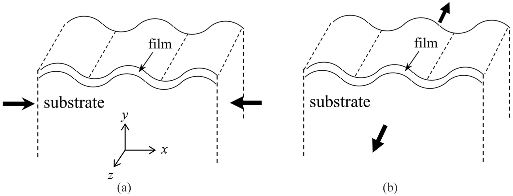
Schematics showing the formation of buckles (wrinkles) during (a) compression along the x-direction and (b) applied tension along the z-direction. The scenarios in (a) and (b) are also termed direct compression and indirect compression, respectively.
While the analytical formulation has been widely employed in analyzing experimental data, relatively few studies have attempted to use numerical simulation to address wrinkle formation.28–34 There are inherent challenges associated with instabilities in finite element modeling. To overcome the existing numerical complexities, in some studies the surface wrinkling phenomenon was simulated in two steps of pre-buckling and post-buckling analysis.31,32,34 The linear modal analysis was mainly performed for the pre-buckling step, and the post-buckling analysis was done via the combination of nonlinear material/geometry models and the imperfection techniques. For the post-buckling step, the incompressible neo-Hookean and Arruda–Boyce constitutive models for elastomers were exploited that require the use of incompressible/hybrid elements. Although applying such elements may have some benefits within the reported numerical frameworks as to simulate the higher-order deformation modes at large strains, incompressible/hybrid elements are available only in limited finite element packages such as ABAQUS. 35 These types of elements are based on relatively complex mathematical theories, and are computationally more expensive compared with regular elements, thus significantly lowering the efficiency for three-dimensional analysis. In addition, they are applicable only for the static analysis and can lead to convergence issues when used with material models that exhibit volumetric plasticity. 33 Aside from the type of elements, other special treatments are required to capture the bifurcation and post-bifurcation wrinkling shapes.
The imperfection methods were categorized into two general types of material and geometrical imperfections, and were widely used in the simulation of instabilities in plates, shells, and cylinders. The geometrical imperfection method, employed more frequently for studying surface instability, may include the mesh, geometry, and boundary condition perturbation techniques (some were directly implemented in the commercial software packages such as ABAQUS). In some studies, a sinusoidal perturbation was directly imposed on the geometry of the film layer which dictates the formation/propagation of sinusoidal-form waves.32,33 In another study, 28 two different types of sinusoidal imperfection and a periodic array of non-interacting exponential surface depressions were specified within the model and studied separately. In a similar fashion, a mesh perturbation technique was applied in that the mesh nodal points were displaced by the sinusoidal perturbation displacement field function. 31 All such imperfection approaches are relatively complex, and they essentially build the formation/propagation of sinusoidal waves into the model. The implementation can be laborious and requires calibration by setting many free parameters. Furthermore, the interpretation and verification of results are not straightforward, which makes it less practical for common users. A more straightforward approach for modeling the wrinkle formation was reported, 36 which however involved special geometric features built into the film surface. Aside from the aforementioned geometrical approach, the material imperfection method is typically based on perturbation via the damage and plasticity techniques. For instance, a non-uniform plastic behavior was built into the model containing an elastoplastic film. 37 Some related studies regarding the material imperfection approach can be found in Andrews and Massabò. 38
The present work aims at developing a simple computational modeling approach to simulate temporal evolution of buckling. Having this capability enables increased accuracy and versatility in predicting wrinkle formation of a relatively stiff thin film on a thick and compliant substrate. The numerical approach may also be employed as a design tool and to study the effect of finite substrate thickness over a wide range of elastic property relationship between the constituents. Moreover, the effects of multilayer thin films and possible viscoelastic and plastic behavior, as well as delamination damage, may all be explored. Our current work seeks to establish a basic modeling framework and assess its feasibility. The proposed methodology is direct, in that the pre/post-buckling simulations can be performed successfully in only one analysis step. The approach is also robust and relatively easy to perform, and it can be implemented with any common finite element code and analysis platform.
In this study, two different film-substrate systems are considered. The first model system consists of a conjugated polymer blend of regioregular poly (3-hexylthiophene) and phenyl-C61-butyric acid methyl ester (P3HT:PCBM) as the thin film, and the intrinsically conductive polymer poly(3,4-ethylenedioxythiophene) and polystyrene sulfonate acid (PEDOT:PSS) is the thin film for second model. The elastomeric polydimethylsiloxane (PDMS) is considered as the substrate for both systems. Note that this is a part of the mechano-optoelectronic composite structure being developed as a functional component of the autonomous structural composites capable of self-powered strain sensing.39–41 The P3HT:PCBM or PEDOT:PSS film was prepared on pre-tension strained PDMS. Upon release of the pre-strain, the film experiences compression leading to buckling. While corrugated films showed improved mechanical resiliency, their optoelectronic performance may be affected.39,41 Developing a robust numerical methodology to predict wrinkling is thus essential in designing the composite layout along with its fabrication.
In the remainder of this article, a brief overview of the buckling theory is first given in section “Brief overview of theory.” Section “Numerical model description” provides the model description. Simulation results are presented in section “Results and discussion,” with attention devoted to comparing the model predictions with the theory on buckling wavelength, critical strain, and amplitude. Details on the analysis procedure and the requirements for the placement of imperfections are also discussed in this section. Highlights of the numerical approach and salient findings are summarized in section “Conclusion.” As evidenced from the current Introduction section, the terms buckling and wrinkling are used interchangeably throughout this article.
Brief overview of theory
Various theoretical analyses on surface buckling instability of a thin film on a compliant substrate have been reported. Although there are no full-field closed-form analytical elastic solutions, some approximated planar solutions are available in the literature.22–25 Here, the force balance approach22,25 is followed and briefly discussed, and the key parameters related to surface buckling are introduced.
The problem considers a semi-infinite substrate under plane strain deformation, with negligible shear stress at the film-substrate interface. It is assumed that the buckling waves are sinusoidally formed throughout the entire width of the film. The classical ordinary differential equation for bending of an elastic film on an elastic substrate subjected to direct compression is

where F is the uniaxially applied compressive force in the film,
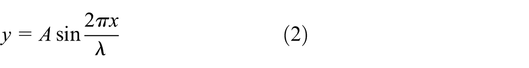
where A is the amplitude of the waves. Without going through the details, the compressive force in the film,
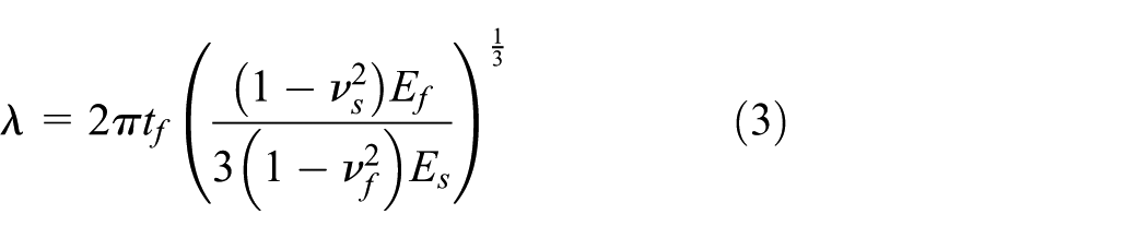
Note that the wavelength shown in equation (3) is only a function of the thickness of the film and the elastic properties of the film and substrate. The critical buckling stress and strain can also be determined, using
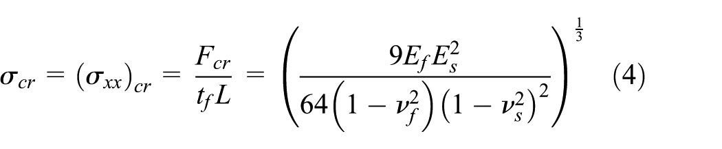
and

Also, the amplitude of the waves, A is derived with the assumption that once the applied compressive strain, e, exceeds

The parameters

Note that since the critical strain
Numerical model description
The finite element simulations are performed on the two-dimensional film-substrate system as shown in Figure 2. Buckling instability under both cases of direct and indirect compression are studied. For the case of direct compression, the surface wrinkles are simulated via both generalized plane strain and plane strain models; however, for the case of indirect compression, plane strain is fundamentally invalid so only the generalized plane strain condition is considered. The generalized plane strain condition takes into account the uniform deformation in the out-of-plane (z) direction and thus the realistic three-dimensional effect. Note that the plane strain assumption is consistent with the theoretical formulation, equations (3)–(6). The problem domain is defined with equal width and depth,
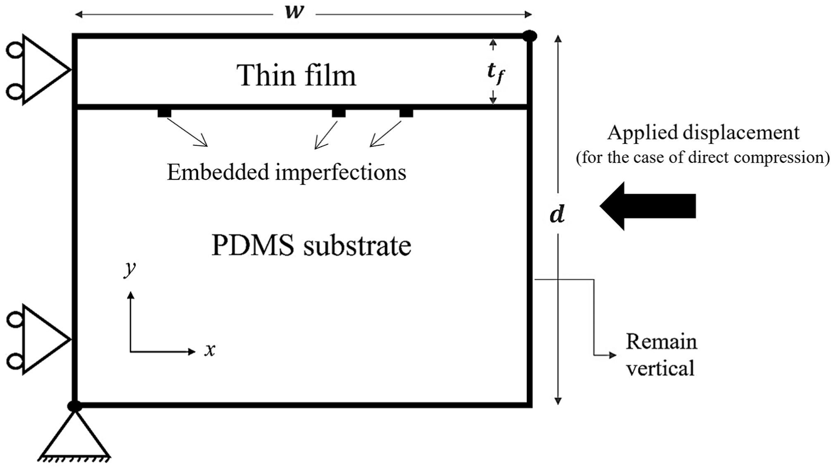
The film-substrate system and boundary conditions used for numerical simulations.
The model generation and simulations were all carried out using the commercial finite element software package ABAQUS (Version 2017, Dassault Systems Simulia Corp., Johnston, RI, USA). Four-noded quadrilateral continuum elements are utilized throughout the model. The top layer is assigned to be the thin film, with the element size increasing gradually from top to bottom. To help initiate buckling instability in the present static linear-elastic finite element model, an “embedded imperfections” approach is adopted here. Some elements were randomly chosen to be endowed with perturbed material properties. In this study, the imperfections, as schematically shown in Figure 2, are distributed in the substrate immediately below the film/substrate interface, with their elastic properties following those of the film material. This proposed methodology is somewhat similar to the material imperfection approach mentioned previously. However, one may interpret this practice as having an imperfect interface with occasional geometric irregularities, which is also physically plausible. Therefore, the imperfections here may be viewed as bearing both the material and geometric natures, but the methodology is straightforward to implement and a fully elastic system may be simulated without any other artificial treatment. It is illustrated in the following section that the methodology is able to generate well-defined wrinkles. The details regarding the desired number and distribution of the embedded imperfections, and the associated wrinkle configurations, are discussed in the following section.
Once a wavy pattern forms, the wavelength
Results and discussion
In this section, the simulation results are presented, with emphasis given to the wrinkling wavelength, amplitude, and critical strain. For illustration purposes, a mesh consisting of 500 columns and 100 rows of elements (total of 50,000) is initially considered for both the direct and indirect compression problems (sections “Direct compression” and “Indirect compression”). The effect of imperfection placement is discussed in section “Effect of imperfection distribution.” Mesh convergence analyses are presented in section “Convergence analysis and comparisons with theory,” along with the comparisons between simulation results and analytical solutions described in section “Brief overview of theory.” Section “Further discussion” provides additional discussion of the numerical technique.
Direct compression
Simulations based on both the plane strain and the more realistic generalized plane strain conditions were performed, but this section only includes the results of generalized plane strain (for P3HT:PCBM film). The plane strain results are presented in section “Convergence analysis and comparisons with theory,” in the context of making comparisons with theories. The wavelengths, critical strains, and amplitudes obtained from all simulations for the two film-substrate systems are also listed in Tables 1 and 2.
Convergence study results (P3HT:PCBM film).

P3HT: poly (3-hexylthiophene); PCBM: phenyl-C61-butyric acid methyl ester; GPE: generalized plane strain; PE: plane strain.
Convergence study results (PEDOT:PSS film).

PEDOT: poly(3,4-ethylenedioxythiophene); PSS: polystyrene sulfonate acid; GPE: generalized plane strain; PE: plane strain.
A linearly ramped negative x-displacement is applied to the right-hand boundary in Figure 2 to simulate direct compression. Both the cases with and without the embedded imperfections are considered. Figure 3 shows the deformed configurations for the generalized plane strain model when the applied displacement reaches 20 µm (or equivalently, 0.02 compressive engineering strain), for the cases with (Figure 3(a)) and without (Figure 3(b)) the embedded imperfections. As can be seen in Figure 3(b), no buckling occurred in the perfect model. With the imperfections, Figure 3(a), however, a uniform wave form was generated throughout the entire width of the specimen in spite of the relatively coarse mesh used. The simulated wavelength and amplitude for this mesh size (50,000 elements) are listed in Table 1.

Deformed configurations for the direct compression problem (under the generalized plane strain condition) when the applied compressive displacement reaches 20 µm, for the case (a) with embedded imperfections and (b) without imperfection. A displacement scaling factor of 10 is used here for better visualization.
The onset of buckling can be identified in several ways, by comparing the simulation history results with and without imperfections. Figure 4(a) shows how the induced vertical (y) displacement at the upper-right corner node evolves with the applied overall compressive x-displacement at the right-hand boundary. The zoomed-in plot is used to identify where the curve for the case with imperfections starts to deviate from that of the perfect model. Figure 4(b) shows the overall reaction force as a function of the applied compressive displacement. Again, a clear deviation point can be identified. In both cases, the critical applied displacement is found to be −18.4 µm, which is equivalent to a critical strain ecr of −0.0184. By monitoring the deformed shape of the model, it was confirmed that the onset of buckling corresponds to this critical strain.

(a) Variation of the induced vertical displacement at the upper-right corner node with the applied displacement during direct compression and (b) Variation of the reaction force with the applied displacement during direct compression.
Indirect compression
A linearly ramped tensile displacement in the z direction is applied to the generalized plane strain model. Figure 5 shows the deformed configurations when the applied tensile strain ezz reaches 0.16, for the cases with (Figure 5(a)) and without (Figure 5(b)) the embedded imperfections. No buckling occurred in the perfect model as seen in Figure 5(b). With imperfections, however, lateral contraction due to the Poisson’s ratio effect instigated buckling and a uniform wave form was generated throughout the entire width of the specimen (Figure 5(a)) despite the relatively coarse mesh used. The simulated buckling wavelength and amplitude for this mesh size (50,000 elements) are also included in Table. 1.

Deformed configurations for the indirect compression problem when the applied tensile strain ezz reaches 0.16, for the case (a) with embedded imperfections and (b) without imperfection. A scaling factor of 5 is used here for better visualization.
A similar procedure as outlined in section “Direct compression” was used to obtain the critical strain. Figure 6(a) and (b) shows the evolutions of the vertical displacement uy and horizontal displacement ux, respectively, at the upper-right corner node as the applied tensile strain ezz increases. In this case of indirect compression, the deviation of the curves with imperfections from their perfect counterparts can be easily detected in only the displacement response as shown in Figure 6. No noticeable deviation can be seen from the load-displacement curve. A consistent critical tensile strain value

Variation of the induced: (a) vertical displacement and (b) horizontal displacement at the upper-right corner node with the applied displacement uz during indirect compression (tension in the z direction).
Effect of imperfection distribution
The embedded imperfections used in the current approach are elements immediately below the interface, with the elastic properties identical to those of the film. A large number of simulations were conducted to explore how the distribution of imperfections can lead to uniform and reliable wrinkling characteristic of a given film-substrate system. It was found that assigning only one imperfect element in the model is sufficient to trigger instabilities; however, different distributions of such defects in the model may alter the induced wrinkling pattern. Here, a systematic study on the effects of uniform and non-uniform distributions of imperfections on the wrinkling patterns is presented.
Consider the film-substrate system shown in Figure 2 (with the dimensions and boundary conditions defined in section “Numerical model description”). Starting with the case of uniformly distributed imperfections, models with various numbers of imperfect elements (or equivalently, with different values of imperfection spacing,
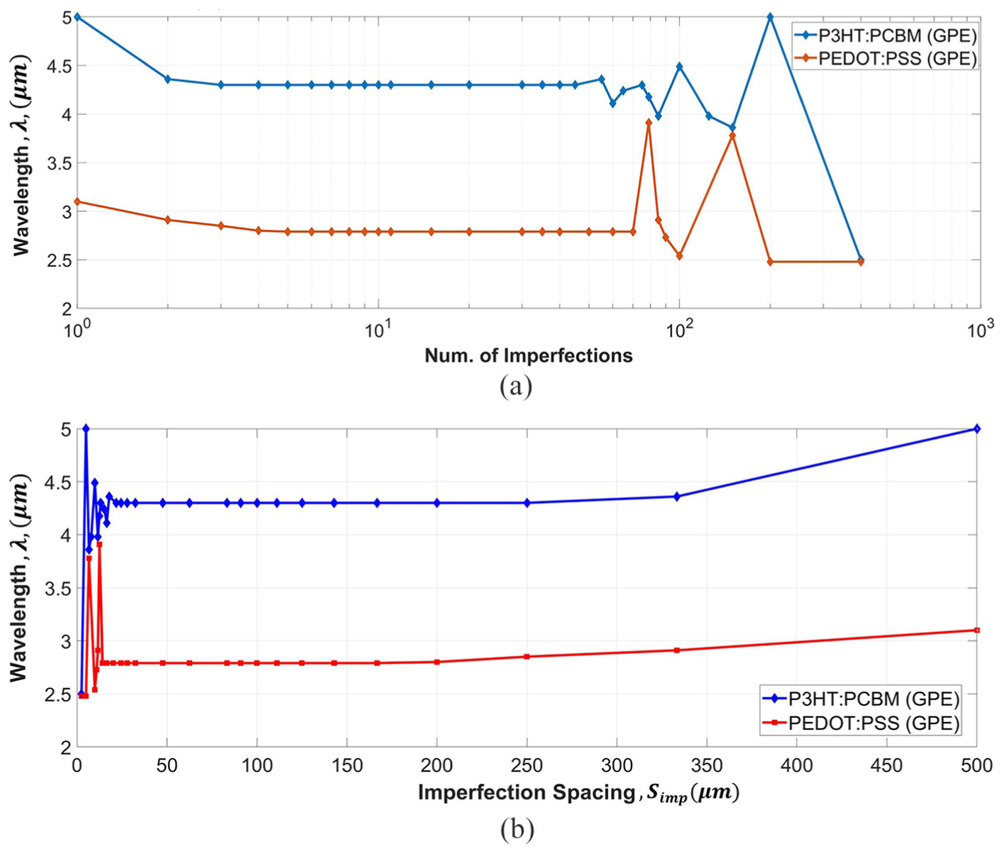
Variation of the wrinkle wavelength, λ, with (a) the total number of uniformly embedded imperfections and (b) the uniform imperfection spacing, Simp. The results pertain to the generalized plane strain (GPE) condition, at e/ecr = 1.20.
The results presented in Figure 7 for the two film materials can be combined by normalizing both the wavelength and imperfection spacing with

The curves in Figure 7(b) normalized by the value of stable wavelength. Three regions with different ranges of imperfection spacing are identified: (a) Imperfection controlled waves (Simp/λ s < 6), (b) Fully developed uniform waves independent of the imperfections (6 ⩽Simp/λ s ⩽ 55) and (c) Non-uniform/localized waves (Simp/λ s > 55).
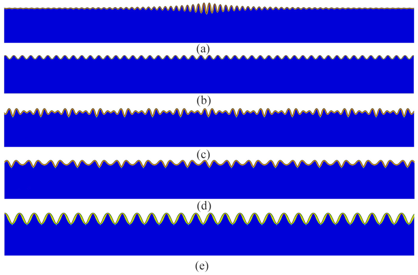
Typical wrinkling configurations obtained from the simulations for various uniform imperfection distributions, for the models with PEDOT:PSS film (the green dots are the embedded imperfections barely visible in these images). (a) Non-uniform/localized wave pattern (Simp/λ s > 55) (b) Fully sinusoidal wave form independent of the imperfection distribution (6 ⩽Simp/λ s ⩽ 55) (c) and (d) Complex wave patterns as the imperfection spacing becoming smaller (Simp/λ s = 3.60 in (c) and Simp/λ s = 2.40 in (d)) (e) Fully imperfection controlled sinusoidal wave (Simp/λ s = 0.89).
In addition to uniform imperfection distributions, a large number of simulations were performed involving random (non-uniform) imperfection distributions. Here, only the salient findings are reported. Depending on the maximum and minimum values of the imperfection spacing,

Typical wrinkling patterns seen for nonuniform distribution of imperfections (for P3HT:PCBM film). (a) Nonuniform and complex wrinkles for a case that does not satisfy the condition of 6 ⩽Simp/λ s ⩽ 55. (b) Uniform wrinkles obtained for a case that satisfies the condition of 6 ⩽Simp/λ s ⩽ 55, independent of the imperfection locations. The images cover only a portion of the surface region. The barely visible green dots are the embedded imperfections, and the scaling factor is 40 for both (a) and (b).
In summary, in the current numerical approach the embedded imperfections are required to trigger buckling instabilities, but a range of
Convergence analysis and comparisons with theory
The results presented in sections “Direct compression” and “Indirect compression” illustrated that the incorporation of imperfections is able to trigger wrinkle formation even with relatively coarse finite element meshes. In this section a comprehensive convergence analysis is presented to assess the numerical approach and to compare the numerical and analytical solutions. The range of mesh refinement spans from a total of 50,000–1,600,000 elements, with the number increasing by a factor of two at each level. We have conducted extensive preliminary simulations and observed that the wavelength tends to become smaller as the mesh is refined, and as a result, more imperfections are required to obtain an objective wavy pattern. Considering the valid range of
The buckling wavelength is considered first. Figure 11 shows the variation of wavelength with the total number of elements. Three sets of numerical results are included—direct compression under generalized plane strain (GPE), direct compression under plane strain (PE), and indirect compression under generalized plane strain. The theoretical wavelength, based on equation (3), is also included in the figure for comparison. It is evident that, in both cases of direct and indirect compression, the wavelength converges to a value slightly lower than the theoretical solution as the mesh becomes sufficiently fine. As described in section “Brief overview of theory,” the theoretical value was derived under idealized assumptions. However, its difference with the converged numerical solution is small. Moreover, no significant difference exists between the numerical results of generalized and regular plane strain models in the case of direct compression.
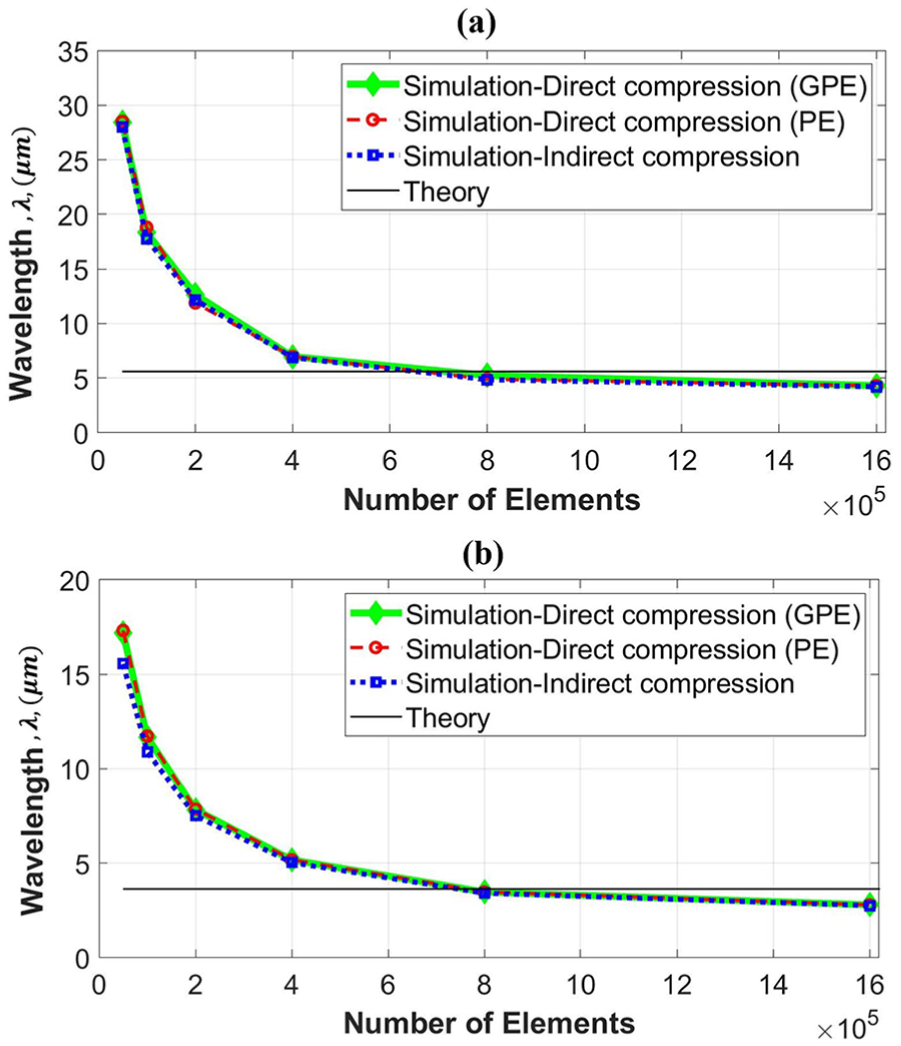
Variation of the simulated wrinkling wavelength with the number of elements for the cases of generalized plane strain (GPE) direct compression, plane strain (PE) direct compression, and indirect compression. The theoretical value is also included for comparison. (a) P3HT:PCBM film, (b) PEDOT:PSS film. The finite element meshes are all composed of four-noded quadrilateral elements in the present work.
Figure 12(a) and (c) shows the variation of simulated critical buckling strain with the number of elements, in the case of direct compression for both the generalized plane strain (GPE) and plane strain (PE) conditions. The theoretical value of

Variations of the simulated critical buckling strain with the number of elements, for the cases of direct and indirect compression. (a, b) P3HT:PCBM film, (c, d) PEDOT:PSS film. Theoretical values are also included for comparison.
Attention is now turned to the wave amplitude displayed by the wrinkles. Note that the theoretical amplitude depends on both the applied strain and the critical buckling strain, equation (6). As shown in Figure 12, the critical buckling strain is different for each analysis. To ensure an objective comparison, a constant ratio of

Variations of simulated amplitudes with the number of elements, for the cases of generalized plane strain (GPE) under direct compression, plane strain (PE) under direct compression, and indirect compression. Note that the numerical results pertain to e/ecr = 1.04 in all cases. The theoretical value is also included for comparison. (a) P3HT:PCBM film, (b) PEDOT:PSS film.
Further discussion
A numerical simulation framework was developed for predicting buckling instability of thin films attached to a thick compliant substrate. The incorporation of imperfections in the model enables simulations on a regular static finite element platform, with no additional treatment or special elements needed. The imperfections perturb the deformation field and trigger the buckling deformation modes. Since under normal circumstances the wrinkling wavelength is much smaller than typical specimen dimensions, a finite-size model is employed with periodic boundary conditions, which proves to be adequate in bringing out a uniform pattern of wrinkles once the critical buckling strain is reached. While the plane strain and generalized plane strain models are used in this study, the approach is readily applicable to any three-dimensional geometry.
In section “Brief overview of theory,” the theoretical basis for wrinkling was summarized. These analytical expressions were derived under the premise of a uniform sinusoidal surface contour. The present numerical simulations, however, can be used to visualize the progression of wrinkle formation. An example is given in Figure 14, where the generalized plane strain model during direct compression is shown under the applied compressive strain of (a)
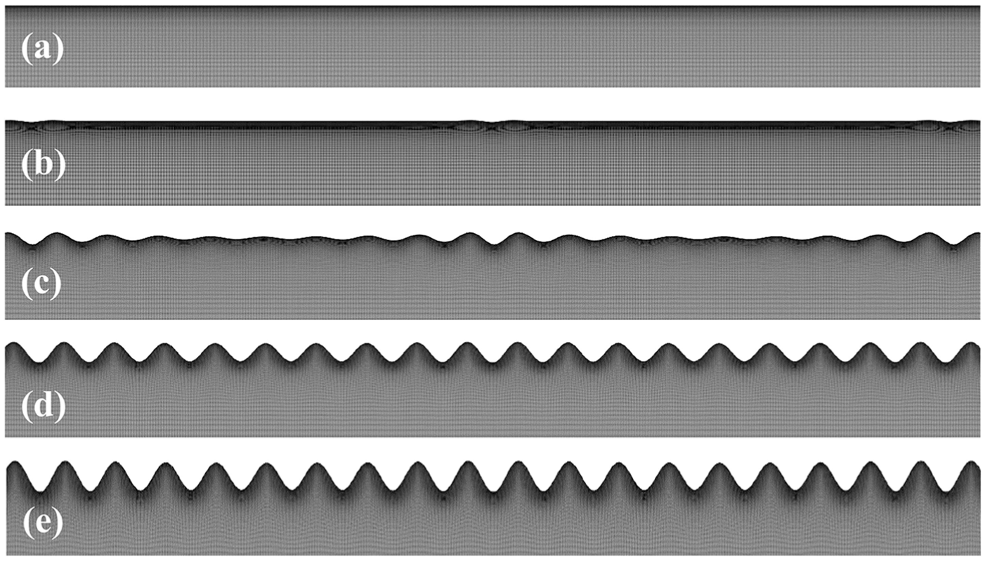
Development of surface wrinkles for the case of generalized plane strain under direct compression (the model consists of 100,000 elements), when the applied compressive strain is (a) e/ecr = 0, (b) e/ecr = 0.9, (c) e/ecr = 1.0, (d) e/ecr = 1.04, (e) e/ecr = 1.30. Images cover only a portion of the surface region, with a displacement scaling factor of 10.
The present technique is not only of significance in numerical studies but also important from the physical point of view. One may draw an analogy between the embedded imperfections and interface defects in an actual specimen. Deviations from a uniform wavy pattern observed in real physical experiments may be rationalized by the numerical simulations with different imperfection placements. Uncommon forms and irregularities of wrinkles can potentially be captured even with a fully linear-elastic film/substrate system. The current approach adds to the existing numerical capability and can be further employed to study how buckling instability is influenced by the thickness ratio and elastic property relationship between the film and substrate materials. It is also well suited as a design tool for the case of multilayer thin films on a substrate. In addition, the approach can potentially be combined with various constitutive behaviors such as viscoelasticity, plasticity, damage, and delamination.
Conclusion
A computational modeling approach was developed to predict the evolution of buckling (wrinkling) of relatively stiff thin coatings above a thick compliant substrate. Buckling instability can be triggered by locally perturbed deformation field through the incorporation of imperfections. Wrinkles form under directly applied compressive strain. When the Poisson’s ratio of the substrate is greater than that of the film, applied tension also induces lateral compressive strain in the film, leading to wrinkling. Instabilities during both of these direct and indirect compression are successfully predicted by the simulations. Through the systematic analyses, a valid range of imperfection density, being able to generate an “objective” wrinkle pattern, was identified. With a sufficiently fine mesh, the simulated wavelength, amplitude, and critical buckling strain converge to near the respective analytical solutions. The current approach does not involve any multi-step or iterative numerical procedure, and is straightforward, computationally efficient, and can be implemented with any finite element analysis platform using regular continuum elements. It is well suited for predicting buckling instability in the design and analysis of thin film systems over a wide range of material and geometric conditions.
Footnotes
Handling Editor: Guian Qian
Declaration of conflicting interests
The author(s) declared no potential conflicts of interest with respect to the research, authorship, and/or publication of this article.
Funding
The author(s) disclosed receipt of the following financial support for the research, authorship, and/or publication of this article: The authors would like to acknowledge NASA EPSCoR CAN (grant #: 80NSSC17M0050), New Mexico Space Grant Consortium, and NASA’s Space Grant College and Fellowship Program for supporting this study.