
Abstract
The upward rolling process is an important forming method of producing cold tailor rolled blank (TRB). In order to describe the flow rule of the deformation workpiece of the TRB accurately, a new three-dimensional (3D) velocity field is firstly obtained based on the weighting of two special velocity fields under extreme conditions. Upon this 3D velocity field, an analytical solution of the force-energy parameters of the above rolling process is strictly derived using the energy method in combination with the unified yield (UY) criterion. After the energy analysis, four kinds of deformation power consumed by upward rolling are solved respectively, and the analytical solutions of rolling torque, rolling force, and stress state coefficient are obtained according to the upper bound theory. Furthermore, the predicted rolling forces are compared with the measured data of upward rolling of CR340 steel. It indicates that the theoretical model using the Tresca yield criterion has the highest prediction accuracy, with an average error of 11.57%, which has demonstrated the importance of the selection of a yield criterion. Meanwhile, it is verified that the theoretical rolling model without considering spread will induce slightly higher results than those considering spread, with an average deviation of 9.80 kN. Finally, the variation of various rolling parameters over time is analyzed, and a reasonable selection range of the ratio of entrance speed to roller speed is obtained, which is around (0.51, 0.67). For the present research, it is seen that the parameter relationship in the present model is clear and the accuracy is reliable, which can be used for the design and optimization of the process parameters of the upward rolling process.
Introduction
In response to the global energy shortage and automobile exhaust pollution, there are tailor rolled blanks (TRBs) that can be widely used for automobile lightweight manufacturing. Since a TRB has a variable section structure, it has an obvious weight-reduction effect on automobile beams, columns, and other components, which is conducive to reducing fuel consumption and exhaust emission.1,2
In the production of a TRB, establishing a reliable rolling force model is crucial for achieving the precise control of roll gap since it is the function of the related process parameters. Because the TRBs have the characteristic of a variable roll gap in the transition zone rather than a constant roll gap, the simple application of traditional rolling force models will induce great errors and cannot meet the control requirements of dimensional accuracy of the workpiece in the transition zone.3,4 Therefore, special researches on the deformation process are very necessary. In terms of simulation, Yu et al. 5 used the ANSYS software to simulate the TRB rolling and obtained the variation rules of rolling force with reduction rate, friction coefficient, initial plate thickness, and roller diameter. Subsequently, to improve the simulation accuracy of the TRB rolling, Zhang and Tan 6 studied the vertical motion of the roller and deduced the calculation formula of vertical roller velocity. Meanwhile, in order to obtain a reasonable shape of TRB transition zone, Wang et al. 7 proposed a curve of transition zone in the form of double power function and deduced the formula of roller velocity under the transition curve. Wu et al. 8 determined the position of the maximum rolling force in the TRB rolling through simulation. Then, he disclosed the influence rules of reduction, friction coefficient, and rolling velocity on the rolling force. 9 Through finite element simulation, Shafiei and Dehghani 10 studied the impact of various rolling conditions on the rolling force of the TRB and came to the conclusion that the variation in contact arc length is the primary factor influencing the variance in rolling force. Huo et al. 11 studied the influence of the ratio of vertical roller velocity to horizontal velocity of workpiece on the transition zone size and rolling force through simulation, and analyzed the contact mechanism of the rolling process. Han et al. 12 studied the deformation laws of TRB in different rolling processes and rolling directions by using the method of simulation combined with experiments, and identified the influencing factors of the length of transition zone under different roll gap conditions. Shi 13 adopted DEFORM to analyze the influence of different transition zone shapes on the metal flow law and rolling mill load in the deformation zone of the rolled workpiece. It should be pointed out that the above simulations are mostly for a specific steel grade or specification and the outputs are the discrete numerical results, which cannot provide effective guidance for the other production conditions.
In order to establish models with good generalizability, clear physical meaning, and rigorous mathematical form, the related analytical researches based on process mechanisms are highly favored. In this regard, the researches based on the engineering method and the energy method have emerged one after another. At first, Zhang and Liu 14 used the engineering method to derive an integral formula of the TRB rolling force with the idea of using a straight line to replace an arc. After that, Sun et al. 15 derived another integral formula of rolling force by introducing shear friction and the differential equations of equilibrium and analyzed the variation rules of unit rolling pressure in the deformation zone under different rolling conditions. During this period, Liu 16 also derived an integral formula of rolling force by using a parabola to replace an arc. Meanwhile, Liu and Zhang 17 deduced a unified expression of differential equation of force equilibrium for TRB rolling according to the force relationship of micro-body. Wang et al. 18 adopted the engineering method to establish a rolling force model applicable to both symmetric and asymmetric conditions of TRB rolling and analyzed the effects of roll speed ratio and friction coefficient on rolling parameters such as thickness ratio. Overall, these studies play an important role in deepening the characteristic understanding of deformation characteristics of TRB. However, due to various assumptions or simplifications in using the engineering method, the integrand function about the rolling force is extremely complex, making it difficult to be integrated subsequently, and thus prevent the acquisition of the expected analytical formula of rolling force. In contrast, the principle of the energy method is plastic variation, 19 which can well avoid this problem by calculating the energy consumption of the rolled workpiece. Moreover, this method can fully account for the geometric characteristics of workpiece deformation and can reduce the difficulty of integral calculation, so it has the potential to obtain an analytical formula of rolling force. Therefore, many scholars have conducted researches on the constraint relationship of rolling parameters for TRB. Zhang et al. 20 first deduced an expression of horizontal velocity of rolled workpiece in the deformation zone based on the volume-invariant condition and carried out the validation by the finite element simulation. Meanwhile, Liu et al. 21 verified that the metal flow per second of each section in the deformation zone of TRB is not equal to each other, and they obtained a new expression of mass conservation for the TRB rolling. Wang et al. 22 deduced a forward slip model and obtained an expression of average deformation velocity on the basis of mass conservation, and found that the roller reduction velocity is the key influencing factor. Ma 23 analyzed the influence of original plate thickness and thickness of thick zone on the extreme thickness difference of TRB by establishing a rolling process model and a motor power model. Subsequently, Zhi et al. 24 proposed four types of transition zone curves and established the corresponding mathematical models to deeply elaborate the matching relationship between the exit velocity of rolled workpiece in the transition zone and the roller reduction velocity. Wu 25 derived the neutral angle and front slip formulas from kinematics and mechanics, and proposed a thickness control method for variable thickness rolling, which is conducive to improving rolling accuracy in thickness direction. Ji et al. 26 proposed a new transition zone curve with a double-power function and analyzed its effect on the speed of roller and rolled workpiece. Through comparison, it was found that the TRB in this case has higher stiffness than the one with linear and polynomial transition zone curves. Liu et al. 27 analyzed the effect of different tension on the stress state, rolling pressure distribution, and rolling length of TRB by using the finite element method. In addition, Zhang et al., 28 Shafiei and Dehghani, 29 Zhang et al., 30 and Zhang 31 studied the stress-strain variation law of different thicknesses of TRB through experiments, providing a method reference for obtaining rolling parameters involved in TRB rolling. Liu et al. 32 established a mathematical model of different deformation parameters in TRB rolling process using the energy method. On this basis, the changing laws between the neutral angle, strip entrance velocity, and the reduction, friction coefficient are analyzed, which is helpful for studying the metal flow characteristics during the rolling process. These studies of rolling mechanisms and velocity fields lay the foundation for the energy analysis of rolling force of TRB. Recently, based on the simplified two-dimensional velocity field, Liu et al. 33 used the energy method to analyze the variable thickness rolling process, derived an analytical solution of rolling force, and verified it through experimental results. However, the energy analysis process is based on a simplified two-dimensional velocity field and the existing models do not take into account the effect of the usage of different yield criteria, which together results in insufficient model accuracy for practical applications.
Therefore, a three-dimensional velocity field that is more in line with the actual rolling situation will be established in this paper, and the unified yield (UY) criterion 34 will be firstly used to analyze the upward rolling process of TRB within the analytical framework of the energy method. The analytical solutions of rolling force and rolling torque will be derived, and the effects of different yield criteria and spread assumptions on the theoretical model will be evaluated. Finally, the model will be validated by comparison with the measured data of upward rolling of TRB. The change rule of various rolling parameters over time will be analyzed, and the reasonable matching relationship between the entrance speed of rolled workpiece and roller speed will be explored, ultimately providing a guidance for process optimization.
Construction of a new three-dimensional velocity field
The upward rolling is one of the main forming methods of realizing the TRB production, and this process will be analyzed in this paper. The Cartesian coordinate system is established with the exit center of the rolled workpiece as the origin, and the directions along the length, thickness, and width of the rolled workpiece are denoted by the x, y, and z axes, respectively. The schematic diagrams of the upward rolling and the workpiece dimensions after rolling can be shown in Figure 1.

Schematic diagram of rolling: (a) upward rolling and (b) workpiece dimensions after rolling.
In Figure 1(a), R is the roller radius and


Since the rolling object is a fixed-length plate, the rolling time and the rolling speed are corresponding, and the rolling speed can be indirectly reflected by the time. The actual contact arc length


where,
In this paper, two velocity fields constructed in 2D space are weighted, which represent two extreme cases of metal flow of the rolled workpiece, so as to construct a new 3D velocity field for subsequent calculation. Here, the velocity field I is an only-extension velocity field, so the strain rate component in the z-direction has

Since the strain rate field satisfies

On the contrary, the velocity field II is an only-spread velocity field, which means that the horizontal velocity of the rolled workpiece in the deformation zone remains constant, and the metal flow only changes incrementally in the width direction, so there is

where, T is the total rolling time,
According to equation (7), the 2D velocity field II can be obtained as:

According to the idea of the overall weighting method, a new weighted velocity field in 3D space is obtained by combining the 2D velocity fields I and II with a weighted coefficient a, as shown below:

Since the velocity field I has no spread and the velocity field II has only spread, the weighting coefficient can be determined by using the ratio of widths before rolling (without spread) and after rolling (having spread), that is,
According to the Cauchy equation, 35 the corresponding strain velocity field components are calculated as

where,
Due to the constant volume condition

According to equations (6) and (11), it can be seen that at the entrance (
Energy analysis of TRB rolling
Internal plastic deformation power
In order to compare the effects of different yielding criteria on the theoretical model of rolling force, the UY criterion 34 is used to conduct the energy analysis. This yield criterion reflects the influence of intermediate principal shear stress on material yield through the weight parameter b. The specific plastic power is the product of equivalent stress and strain rate. It can be used to calculate the internal plastic deformation power caused by plastic deformation in a deformed rolled workpiece according to the energy method. The specific plastic power of the UY criterion is further derived in Zhao et al., 36 achieving a generalization of the specific plastic power of a series of linear yield criteria. The expression is

where,
Since there are

After calculation,

where,

In equation (13),

Substituting equations (14) and (16) into equation (13), one can obtain the internal plastic deformation power

Unlike the internal plastic deformation power calculated based on a certain yield criterion, this equation can consider the impact of different yield criteria by changing the value of b.
Shear power
According to the velocity field described by equation (9), it can be seen at the entrance of the rolled workpiece (

Then, the shear power

At the exit of the rolled workpiece (

Therefore, the shear power

According to equations (19) and (21), the total shear power

Since the value of

Friction power
During the upward rolling process, the velocity components

Since the direction of friction stress

Therefore, the friction power

According to equation (1), the directional cosines

where,

Integrate the forward and backward slip zones of the deformation zone with the neutral point as the boundary point, that is,

where,

Substituting equations (29) and (30) into equation (28), it gives the friction power

Tension power
When there is front and back tension in the rolling deformation zone, the tension power

where,
Total power functional
Substitute equations (17), (23), (31), and (32) into the following equation, one can obtain the total power functional

To solve for the neutral angle and the minimum value of the total power functional

where, the first derivative of each power is


where,
According to equations (33) and (34), the neutral angle

where,

where,
It is important to note that the present rolling force result is essentially an analytical solution with clear physical meaning and rigorous mathematical expression, which is different from the numerical simulation results of Wu8,9 and Shafiei and Dehghani. 10 It should also be noted that based on the above formulas, substituting different b values will obtain expressions for rolling force, torque, and stress state coefficient corresponding to different yield criteria.
Comparative analysis and discussion
Verification and analysis of rolling force
For the validation of the model, the same process parameters in Zhang
39
are chosen for the calculation in this paper. The experimental material is CR340 steel and the rolling equipment is 450 mm four-high reversing mill. The rolling process is controlled by means of a dynamic point setup model, micro-tracking, and dynamic thickness control. The initial thickness of plate
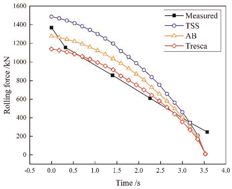
Comparison of theoretical and measured values of rolling force of TRB.
As shown in Figure 2, the upper and lower solutions of rolling force are obtained with the TSS and Tresca yield criteria, respectively, while the results located in the center are based on the AB yield criterion. All the three model results have the same predictive trend, but in general, the predictive results of the Tresca yield criterion are in better agreement with the measured results. By analysis, it is known that the theoretical modeling is based on the upper bound method in this paper, which will result in slightly higher results (generally 10% higher). However, the Tresca yield criterion has the characteristic of giving lower results, which can offset the errors due to the upper bound method and provide more reasonable prediction results. At the beginning stage of upward rolling, the motion state of roller in the vertical direction undergoes a sudden change. The rolling process set in the theoretical model is a continuous change, so the theoretical model cannot accurately describe this change, resulting in differences between the measured data and the theoretical data. This requires another perspective of research methods, such as finite element simulation and artificial neural networks, to supplement. Additionally, it should be mentioned that in order to improve the thickness accuracy of a plate, a preloading force is applied during actual rolling to ensure smooth bite of the rolled workpiece. According to the measured rolling force at the end of rolling, the preloading force is 246 kN. Due to the lack of consideration of the influence of preloading force during the establishment of the present theoretical model, and assuming that the rolling process is continuous. Therefore, the measured values at the end of rolling are not zero, resulting in numerical mismatches.
To further explain the model accuracy, the calculated rolling forces are verified with the measured data, as shown in Table 1.
Comparison of theoretical predictions of various yield criteria and measured values.

In Table 1,
In order to analyze the impact of spread on the rolling force, the rolling forces are predicted separately under the conditions considering the spread and neglecting the spread (a = 1). The comparison results are shown in Figure 3:
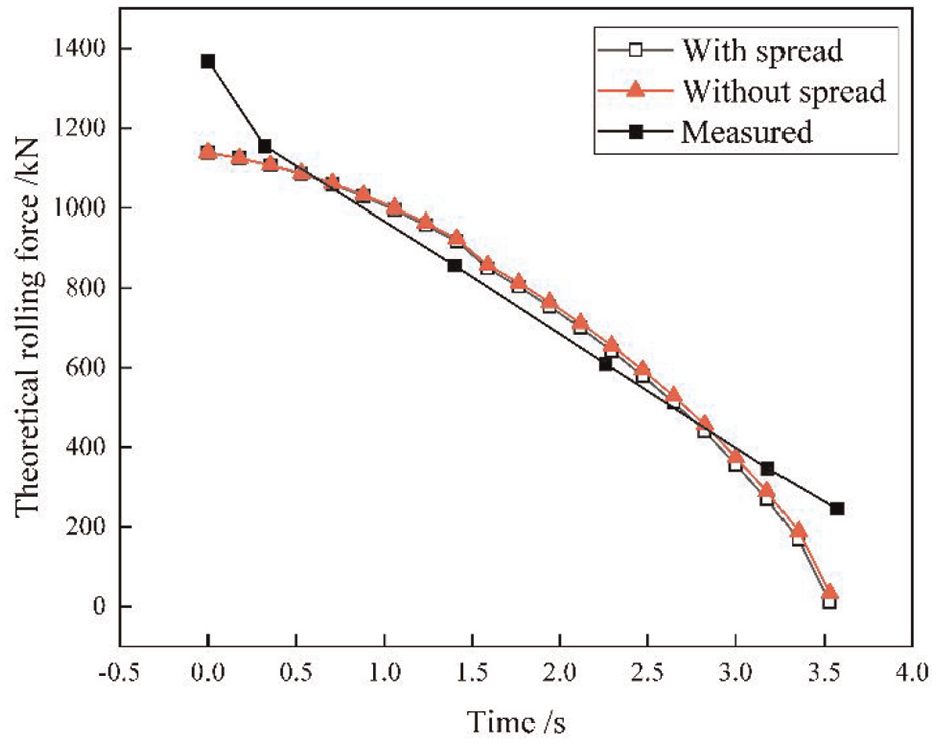
Comparison of theoretical rolling forces under the conditions of considering the spread and neglecting the spread.
As Figure 3 illustrates, the theoretical rolling force model without considering spread results in generally slightly higher results than that considering spread, with a maximum deviation of 22.64 kN and an average deviation of 9.80 kN. The reason is that when the width direction is restricted for deformation, the metal flow in this direction is hindered, resulting in the need to apply additional pressure in the thickness and length directions of the rolled workpiece to deform this part of the metal, which requires a higher rolling force. This is consistent with relevant prior knowledge and actual rolling situation. Meanwhile, through the comparative study here, it can also confirm the feasibility of the hypothesis of plane deformation of the TRB in the existing Liu et al. 21 However, for the upper bound method, due to the high results generated by this method, the adoption of a 3D velocity field by considering the spread can reduce the predicted rolling force, thus proving that the construction of a 3D velocity field is possible and more approaching to real results. The focus of this paper is to build a rolling force prediction model in the upward rolling process. Anisotropy in the deformation and mechanical properties of plates is also a very important research direction, which will be carried out in the follow-up research.
Analysis of rolling parameter rules
Through the study of the conservation of second flow rate and the position of neutral point, it is found that when the roller speed
Assuming that the flow velocity of the rolled workpiece increases linearly from the entrance to the exit, and noting that at the beginning of upward rolling,

where,

Variation curves of neutral position for different c values.
As shown in Figure 4, all neutral point curves show a slow downward trend, indicating that as the upward rolling progresses, the relative position of the neutral point will slowly move toward the entrance. As the c value increases, the proportion of backward slip zone in the rolling deformation zone gradually decreases, implying that the proportion of friction zone driving the metal into the roll gap is gradually decreasing. On the contrary, when the c value decreases to a certain value, such as c = 0.51, it cannot be guaranteed that there will be a neutral point throughout the entire rolling time, that is, the backward slip zone will occupy all. Moreover, when
The influence of different neutral point positions on the friction powers in the forward and backward slip zones in the deformation zone at different c values is presented in Figure 5:

The friction powers in the forward and backward slip zones with different c values: (a) c = 0.8, (b) c = 0.7, (c) c = 0.67, and (d) c = 0.6.
As shown in Figure 5, the c value is assigned specific and reasonable values when used, and different results are obtained. As the c value decreases, the two friction power curves alternate between c = 0.67–0.7. Due to the positive work done by the friction in the backward slip zone, when the friction power in the backward slip zone is greater than that in the forward slip zone throughout the entire rolling process, it will be more conducive to the biting of the rolled workpiece at c = 0.67. Ultimately, it can be concluded that the reasonable interval for

Variation of each power during upward rolling.
As shown in Figure 6, both the internal plastic deformation power and friction power occupy a larger proportion of the total power for most of the time, and the decreasing trend of the internal plastic deformation power was more significantly affected by the reduction rate. Since the cross-sectional areas of plate entrances and exits are small, the percentage of the shear power is small. However, in the middle and late stages of the rolling, the effect of shear is greater than that of friction. Since it is currently difficult to directly measure power such as friction power and shear power, but the rolling force is a measurable variable, which can be compared directly. The role of those powers in the derivation process is to use them as a medium to derive the expression of rolling force.
As shown in Figure 7, the stress state coefficient generally shows a gradual increase as rolling proceeds. However, at the end of rolling, due to the rapid decrease in theoretical rolling force, there is a slight decrease in the stress state coefficient when calculated with the actual deformation zone length

Variation of stress state coefficient with time.
Conclusions
In this paper, a new three-dimensional weighted velocity field for upward rolling is obtained by weighting the only-extension and only-spread velocity fields. By combining the unified (UY) yield criterion, the energy method is used to analyze the required power for rolling, and analytical solutions for rolling force, rolling torque, and stress state coefficient are derived in sequence. The main findings are as follows:
(1) By comparison with the measured rolling forces of CR340 steel during upward rolling, the prediction accuracy of rolling force in this model under different yield criteria is compared and verified. The results indicate that the theoretical model has higher prediction accuracy when using the Tresca yield criterion. In addition, after verification, the theoretical rolling force model when neglecting spread will result in generally slightly higher results than that considering spread, and the maximum deviation is 22.64 kN.
(2) The variation of various rolling parameters with time during upward rolling is analyzed in this paper. The results show that the relative position of the neutral point slowly moves toward the entrance end, indicating that the proportion of backward slip zone in the rolling deformation zone gradually decreases. From the perspective of preventing slipping and facilitating the biting of the rolled workpiece, the reasonable range of the ratio between the entrance speed and the roller speed
(3) Statistics on the various powers of upward rolling revealed that the internal plastic deformation power and friction power occupy a larger proportion of the total power, and the shear power was smaller. However, in the middle and late stages of rolling, the effect of shear is greater than that of friction. In addition, the stress state coefficient shows a general trend of gradual increase due to the rapid decrease of the rolling force.
Footnotes
Appendix
Handling Editor: Sharmili Pandian
Declaration of conflicting interests
The author(s) declared no potential conflicts of interest with respect to the research, authorship, and/or publication of this article.
Funding
The author(s) disclosed receipt of the following financial support for the research, authorship, and/or publication of this article: This research was supported by the National Natural Science Foundation of China (Grant no. 52074187, 52274388). The authors also wish to acknowledge valuable suggestions from reviewers.